400W Solar Module: Complete Installation Guide in 6 Steps
For 400W solar module installation: set tilt ±5° from local latitude, space brackets 1.2–1.5m; secure panels with 50–70N·m torque, use PV1-F 6mm² cables (≤3% voltage drop); connect to inverter matching 45V open-circuit voltage, and ground with ≤4Ω resistance for safety and efficiency.
Site Selection and Preparation
A poorly selected site can lead to an energy production drop of 20% or more, directly impacting your payback period. For a typical residential system, this could mean losing over $120 in annual energy savings per module. The goal is to maximize exposure to the sun's path. In the Northern Hemisphere, this means a true south-facing orientation, though orientations between southeast and southwest can still capture over 95% of optimal sunlight. The tilt angle is equally critical; for most permanent installations, setting the tilt angle to roughly equal your local latitude will yield the highest annual energy output. For instance, a home at 40° latitude should aim for a 35-45° tilt. Before you even unbox the mounting hardware, spend time analyzing the sun's movement across your proposed site across all seasons.
Even small shadows have an outsized impact on high-efficiency 400W modules, which often use half-cut cell technology. A shadow covering just 10% of a module's surface can cause a power loss of over 50% because it can disable entire strings of cells within the panel. You must survey the site at different times of the day and year, noting potential obstructions. Use a solar pathfinder tool or a dedicated smartphone app to generate a annual sun chart specific to your coordinates; this provides a data-driven approach rather than a guess. The ideal location requires a minimum of 6 hours of direct, unobstructed sunlight daily, with peak sun hours occurring between 9 AM and 3 PM. For a ground-mounted system, this means clearing vegetation within a 20-foot radius to prevent future growth from casting shadows. For roof-mounted systems, measure the distance from ridges, vents, and chimneys. A good rule is to keep modules at least 3 feet away from any roof peak or obstruction to avoid wind-driven snow and ice damage. The structural integrity of your roof is non-negotiable. Most composite shingle roofs are designed to handle a load of 20-25 pounds per square foot. A typical 400W panel weighs about 45 pounds and occupies 22 square feet, resulting in a static load of roughly 2 pounds per square foot. However, you must factor in dynamic loads from wind and snow, which can add another 15-30 PSF. If your roof is over 15 years old, a professional inspection is highly recommended to verify its ability to support the additional 600-800 pounds for a 10-panel array. The upfront cost of 200−500 for an inspection is insignificant compared to the risk of structural failure.
Always prioritize a location with the simplest wiring path back to your inverter and main electrical panel. Every extra 10 feet of 10-gauge copper DC wiring between your modules and inverter will result in approximately a 0.5% loss in system efficiency, costing you valuable harvested energy over the system's 25-year lifespan.
The permitting process can take 2-4 weeks and may require a detailed site plan, including a one-line electrical diagram and a structural engineering report. Budget for this; permit fees typically range from 150 to 600 depending on your locality.
Mounting System Installation
The mounting system is the unsung hero of your solar array, responsible for securing your significant investment against 90 mph winds, heavy snow loads up to 40 psf, and decades of weathering. A properly installed racking system, which typically accounts for 10-15% of your total hardware cost, ensures the structural integrity and optimal performance of your 400W panels. Choosing between aluminum and steel is the first decision; aluminum alloys like 6005-T5 offer a solid strength-to-weight ratio (40,000 psi yield strength) and corrosion resistance at a weight of approximately 1.2 lbs per foot, while galvanized steel provides higher load-bearing capacity (50,000 psi) for larger arrays but weighs over 2.1 lbs per foot, adding 150-200 lbs to your total roof load.For most residential composite shingle roofs, aluminum is the standard choice due to its 50-year lifespan and minimal maintenance. The installation process begins with attaching flashing-mounted roof attachments, commonly called lag bolts, into the roof rafters. The absolute priority is hitting the structural rafters, which are typically spaced 16 or 24 inches on center.
For a 2x6 rafter (actual width 1.5 inches), a ⅜-inch diameter lag bolt with a minimum length of 5 inches is required. This ensures at least 2.5 inches of thread engagement into the solid wood, providing a pull-out strength of over 600 lbs per attachment. Using an impact driver or a high-torque drill, tighten each bolt to a precise 45 ft-lbs; under-tightening risks the module shifting in high winds, while over-tightening (beyond 55 ft-lbs) can strip the rafter wood, reducing its holding capacity by up to 80%. Once all attachments are secured and sealed, the horizontal rails are mounted. These rails must be perfectly level, as a deviation of more than ⅛ inch over a 10-foot span can induce stress into the solar panels' frames during installation. The spacing between rails is determined by your module's dimensions. A typical 400W panel is approximately 82 inches long and 41 inches wide, requiring two rails set 56 inches apart, center-to-center, to provide four clamping points.
Material Property | Aluminum Alloy (6061-T6) | Galvanized Steel |
Typical Cost per Foot | 4.50−6.00 | 3.50−5.00 |
Weight per Foot | 1.1 - 1.3 lbs | 2.0 - 2.3 lbs |
Yield Strength | 35,000 - 40,000 psi | 50,000 - 60,000 psi |
Corrosion Resistance | Excellent (AlOx Layer) | Good (Zinc Coating) |
Recommended Max Span | 6 feet | 8 feet |
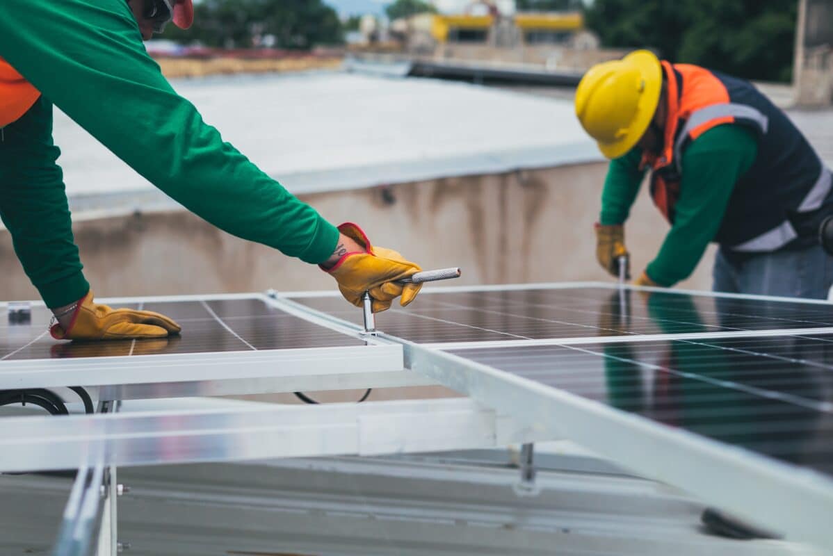
After the rails are secured, the next step is installing the module clamps. Use only manufacturer-approved clamps, as they are engineered to match the rail profile and module frame. There are two types: mid-clamps and end-clamps. Mid-clamps are placed between two panels, securing both simultaneously, while end-clamps are used on the outer edges of the array. Leave a precise ¼-inch gap between adjacent modules to allow for thermal expansion; panels can expand and contract by nearly 0.5 inches over a temperature range of -40°F to 150°F.
Module Placement and Fixing
Lifting and securing a 400W solar panel, which weighs approximately 45 lbs and measures 82 by 41 inches, is a precise two-person operation where a 1-inch misalignment can complicate electrical connections and induce long-term frame stress. The goal is to achieve a perfectly flat array with uniform gaps, ensuring both maximum energy harvest and a 25-year service life. Each panel represents a 250−350 investment, and improper handling is the leading cause of micro-crack formation, which can degrade power output by 5-15% annually and is often not covered by manufacturer warranties. The process begins with staging the panels near the installation area, ideally using a mechanical lift or ladder-based pulley system for roof work to avoid muscle strain and potential drops. Always use a four-point lift technique with two people on opposite sides of the panel, keeping the glass surface at an angle less than 20 degrees from horizontal to minimize flexing in the aluminum frame. The glass can withstand up to 5400 Pa of pressure (equivalent to a 110 mph wind load) but is vulnerable to point impacts from tools or sharp corners.
The clamp's mechanical specifications are critical; a stainless steel mid-clamp should have a minimum tensile strength of 80,000 psi and engage at least 3.5 mm of the panel's frame channel. Torque the clamp bolts to the manufacturer's exact specification, which is usually 15-18 ft-lbs for most systems. Under-tightening below 12 ft-lbs risks the panel shifting during high-wind events, while over-tightening beyond 20 ft-lbs can deform the aluminum frame, voiding the warranty and creating a stress concentration point. The sequential order of clamping matters: start with the bottom two clamps to loosely position the panel, use a 48-inch aluminum level across the top of two adjacent panels to ensure perfect planar alignment, and then secure the top clamps before finalizing all torques.
Installation Error | Resulting Issue | Performance & Financial Impact |
Frame Deformation | Induced micro-cracks in silicon cells | 5-10% annual power degradation; $120/year lost revenue |
Incorrect Torque | Panel slippage or frame stress | Risk of array failure in winds >55 mph |
Uneven Gaps | Thermal expansion stress | Potential glass breakage in winter (-40°F conditions) |
Improper Lift | Glass or cell damage | Immediate power loss up to 30%; $750 panel replacement cost |
The aluminum frame has a thermal expansion coefficient of 23 µm/m·°C. On a 82-inch (2083 mm) long panel, a temperature swing from 70°F to 150°F (21°C to 65°C) causes the frame to expand by approximately 2.1 mm. Without sufficient gap, panels can press against each other, transferring stress to the glass and cells. After physically securing each panel, immediately connect the pre-wired MC4 connectors. These are weather-sealed connectors rated for IP67, meaning they can be submerged in 1 meter of water for 30 minutes. Ensure you hear a definitive click when male and female connectors join, and then tug firmly to confirm a secure connection. A loose connection can lead to arcing, creating a fire hazard and resistance that can waste over 3% of your power as heat. The entire placement and fixing process for a 10-panel array should take a two-person team no more than 3 hours, averaging 18 minutes per panel.
Electrical Wiring and Connections
A single wiring error can lead to a 15% system efficiency loss, create a serious fire hazard, or void your equipment warranties. For a typical 10-panel, 4000W system operating at 40VDC per panel, the combined string voltage can easily exceed 350VDC, a potentially lethal amount of electricity. The core principles are using the correct wire gauge, making waterproof connections, and implementing proper overcurrent protection to ensure your system runs safely for its entire 25-year lifespan.
l Wire Sizing: Using undersized wire is a common and costly mistake. For a 400W panel with a maximum Imp (Current at Maximum Power) of approximately 10 amps, the National Electrical Code (NEC) requires a minimum of 10 AWG copper wire for runs up to 20 feet from the array to the inverter. For every additional 10 feet of wire length, you can expect a 0.5% voltage drop; a 50-foot run with 10 AWG wire would result in a 2.5% power loss, equating to over 100 kWh of lost energy production per year, worth about 15−20 at average utility rates. For longer runs, you must increase the wire diameter. A 50-foot run should use 8 AWG wire to keep voltage drop below the critical 1.5% threshold. The cost difference between 10 AWG and 8 AWG PV wire is about 0.40perfoot,meaninganextra40 investment for a 100-foot run can save you nearly $200 in lost energy over a decade.
l Connector Integrity: All modern 400W panels come with MC4 connectors. These are industry-standard, IP67-rated connectors designed to handle up to 30 amps and 1000VDC. The key is to ensure a perfect, waterproof seal. When connecting, you must hear and feel a solid click. After connecting, a firm tug test is mandatory to confirm the lock mechanism is fully engaged. A loose connection creates resistance, which generates heat. A connection with just 1 ohm of extra resistance at 10 amps will waste 10 watts of power as heat (P = I²R = 10² * 1), and over a sunny day, this can heat the connector to over 150°F, melting the plastic and creating an arc fault risk.
If your inverter has a maximum voltage input of 500VDC and a current input of 15 amps, you can wire panels in series. For example, connecting 10 panels in a single string would multiply the voltage (40V x 10 = 400VDC) while keeping the current at roughly 10 amps, well within the inverter's limits. Always check the inverter's minimum operating voltage (often around 150V) to ensure the string voltage will not drop below this threshold on cloudy days or in high temperatures, when voltage output decreases. Use a digital multimeter to verify the open-circuit voltage (Voc) of the entire string before plugging it into the inverter.On a cool, sunny morning (around 50°F), the actual Voc can be 15% higher than the rated STC value; a string rated for 400V could momentarily produce 460V, which must still be under your inverter's maximum 500VDC limit. All wiring must be secured every 24 inches with UV-resistant cable ties and routed through dedicated conduit where exposed.
Grounding and Safety Checks
A properly grounded system provides a low-resistance path (ideally below 25 ohms) for stray electricity to safely dissipate into the earth, preventing electrocution and fire risks. For a 4000W system, a single lightning strike can induce a transient voltage surge exceeding 6000 volts, which without proper grounding, will fry your 2000 inverterand potentially ignitearo offire.
l Equipment Grounding: Every metal module—panel frames, mounting rails, and the inverter chassis—must be bonded together with a continuous grounding conductor. Use a bare copper wire, 6 AWG or larger, as your main Equipment Grounding Conductor (EGC). This wire connects to each rail via listed grounding lugs, which must be rated for direct burial and corrosion resistance (typically stainless steel or bronze). The torque specification for these lug bolts is critical; under-tightening below 15 ft-lbs creates a high-resistance connection that can overheat, while over-tightening above 25 ft-lbs can strip the threads. The entire array should form a single, continuous ground path with a resistance of less than 1 ohm between any two points.
l Ground Electrode System: The EGC must eventually terminate at your home's Grounding Electrode System (GES). This is typically two 8-foot long, ½-inch diameter copper-clad ground rods, spaced at least 6 feet apart and driven fully into the earth. The connection between your 6 AWG EGC and the ground rod must be made with an acorn clamp, listed for direct burial. The NEC requires the resistance to ground of this electrode system to be 25 ohms or less. To verify this, you must use a ground resistance tester (an 800tooloftenrentedfor75/day). In dry, sandy soil, resistance can exceed 100 ohms, requiring additional rods or a ground enhancement material like bentonite clay to achieve compliance.
After all connections are made, a series of performance and safety checks are mandatory before grid interconnection. These tests validate the insulation integrity of your wiring and ensure all safety mechanisms function correctly.
Safety Check | Procedure & Tool | Pass/Fail Criteria |
Insulation Resistance Test | Use a megohmmeter (500VDC output) to test between conductors and ground. | Resistance must be greater than 1 MΩ (1,000,000 ohms). Any reading below this indicates damaged insulation, often from a pinched wire during installation. |
Continuity Test | Use a multimeter to verify the resistance of the entire grounding path. | Resistance between the farthest panel frame and the ground rod must be less than 1 ohm. |
DC String Voltage Test | Measure VOC and ISC of each string with a multimeter and clamp meter. | Voltage must be within ±5% of calculated value. Current must be within ±3% of panel specifications. |
Rapid Shutdown Test | Activate the rapid shutdown switch (NEC 690.12). | Inverter output must drop to below 30VDC within 30 seconds of activation at the array. |
Ensure all conduit fittings are weather-tight and all wiring is secured at least every 36 inches with UV-resistant nylon ties. Check that no cables are draped across sharp roof edges or within 6 inches of any roof edge where they could be abraded by weather or animals. These final checks, which take about 2 hours for a 10-panel system, are the last barrier between a safe, code-compliant installation and a hazardous one.
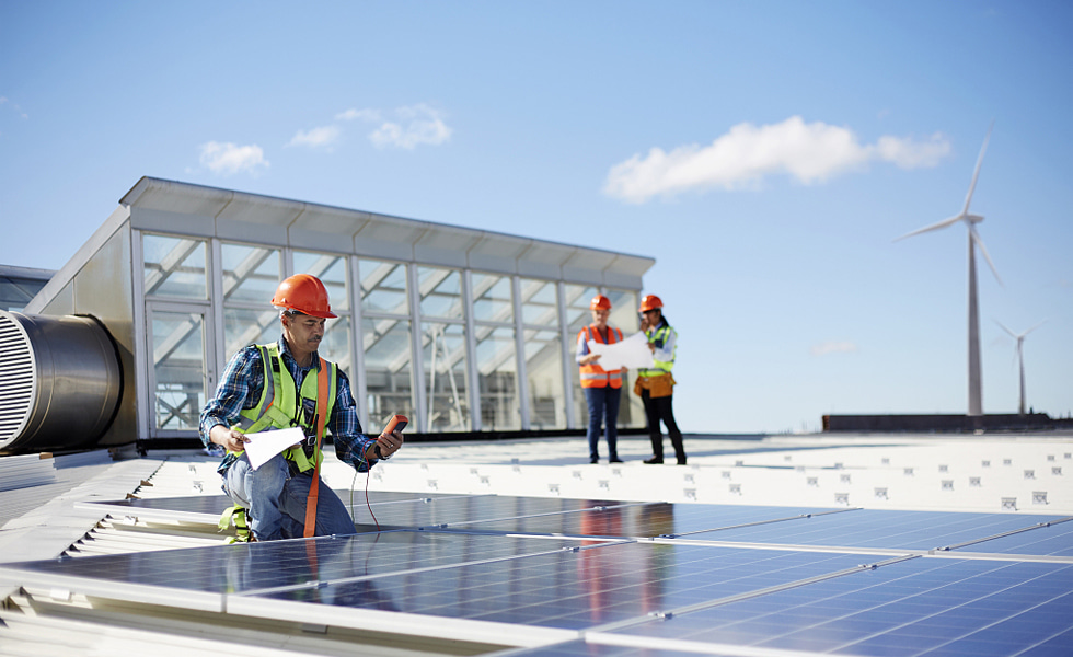
System Testing and Activation
A meticulous, multi-stage commissioning process is critical to validate the performance and safety of the entire system, ensuring it operates at peak efficiency—typically between 97-99% of its rated capacity—from the first day. Skipping these steps risks voiding your 25-year warranty on a $12,000 system for the sake of saving 2 hours of testing time. The goal is to methodically bring each module online, comparing its real-world output against engineered expectations with a tolerance of just ±3%.
With all DC connections made and the DC disconnect switch still in the OFF position, double-check every MC4 connector for that audible click and perform a final tug test. Verify that the 6 AWG grounding wire has a continuous, low-resistance path from the array to the ground rods, measuring less than 1 ohm. Confirm the inverter is securely mounted at least 12 inches off the ground in a well-ventilated area, clear of direct sunlight and moisture, with a minimum 6 inches of clearance on all sides for airflow. Once the physical inspection is complete, the electrical testing begins. Using a true RMS multimeter, measure the open-circuit voltage (Voc) of each string at the inverter's DC input terminals. On a cool, clear morning (around 50°F/10°C), expect the voltage to be 10-15% higher than the panel's standard test condition (STC) rating. A string of ten 400W panels with a Voc of 40V each should read approximately 440-460 VDC; a reading outside the range of 420-480 VDC indicates a wiring error or a faulty panel. Next, use a DC clamp meter to measure the short-circuit current (Isc). With the array exposed to full sun, this reading should be within 5% of the panel's spec sheet value, typically around 10.5 amps for a 400W module.
Most modern inverters take 3-5 minutes to perform their internal self-checks, establish a grid connection, and begin the "ramp-up" process. Monitor the inverter's display for the first 15 minutes of operation, watching for the AC power output to stabilize. A 4000W system should be producing between 3000-3800 watts during its initial run, depending on the time of day and sun angle. The final and most critical step is performance validation. Using a wireless monitor or the inverter's built-in web interface, track the system's energy production over its first 72 hours of operation. Compare the total kWh produced against the projected output from a tool like PVWatts. Your system should achieve 95-100% of its estimated output on a clear, sunny day.
Performance Test | Measurement Tool | Expected Value & Tolerance |
DC String Voltage (Voc) | True RMS Multimeter | Calculated Voc ±5% (adjusted for temperature) |
DC String Current (Isc) | DC Clamp Meter | Panel Isc rating ±5% |
AC Power Output | Inverter Display / AC Clamp Meter | Rated inverter power ±10% (during peak sun) |
Insulation Resistance | Megohmmeter (500VDC) | >1 MΩ (1,000,000 ohms) |
Energy Production (24h) | System Monitor / Meter | PVWatts estimate ±10% (on a clear day) |
After 72 hours of stable operation, your system is officially commissioned. Schedule a final inspection with your local utility provider to permanently activate your net metering agreement, which typically processes within 5-10 business days.