How To Maintain Monocrystalline Silicon Photovoltaic Panels For Optimal Performance
To ensure the efficient operation of monocrystalline silicon modules, it is recommended to perform professional cleaning 1-2 times per month. Dust accumulation can lead to a decline in power generation efficiency of more than 15%.
Time Cleaning
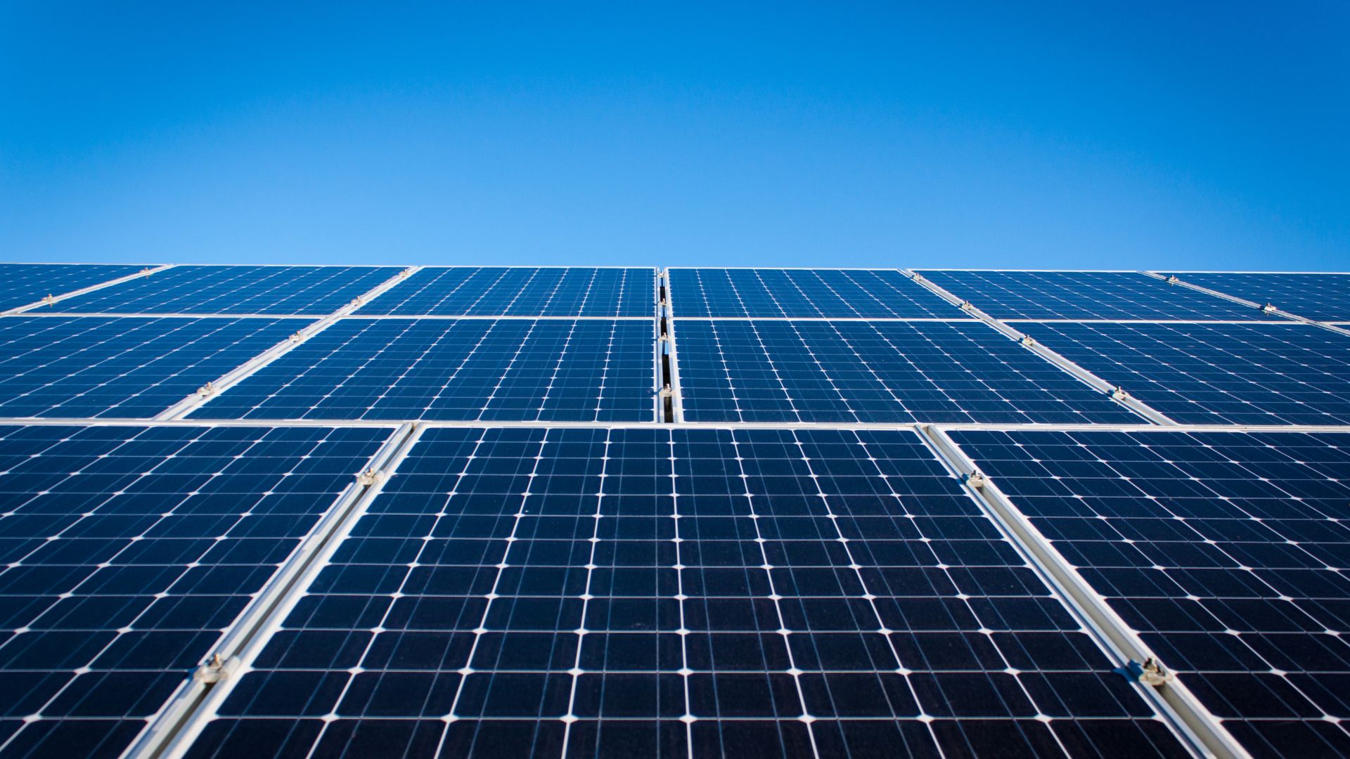
On the surface of a 1.63-square-meter monocrystalline silicon module, a layer of floating dust only 0.1 mm thick can cause the light transmittance of 3.2 mm tempered glass to drop from 91% to 78%, leading to an instantaneous drop in the output power of a single 550W module to approximately 470W.
When the dust density reaches 20 g/m², the short-circuit current (Isc) of the cells inside the module will drop by 8.5%. While the open-circuit voltage (Voc) only fluctuates by 1.2%, the overall Fill Factor (FF) will deteriorate by more than 5%.
If dust removal is not performed for 90 consecutive days, the cumulative annual power generation loss will reach 15% to 22%. For a 5 MW industrial and commercial power station, this represents an annual revenue gap of 330,000 RMB in electricity fees.
Pollutant Type | Coverage Thickness/Density | Efficiency Decay Ratio | Local Temperature Rise |
Dry Floating Dust | 10g/㎡ | 4.5% - 6.2% | 2.5°C - 4.0°C |
Sticky Bird Droppings | 5 cm² Coverage | 12.5% - 35% | 15.0°C - 28.0°C |
Industrial Oil Fume | 0.05mm Film Layer | 18% - 25% | 5.5°C - 9.0°C |
Construction Cement Powder | 15g/㎡ | 20% - 45% | 8.0°C - 12.0°C |
The window for wiping operations must be strictly limited to early morning from 5:00 to 7:30 or after 18:30 in the evening. At these times, the solar radiation intensity is lower than 200 W/㎡, and the backplane temperature of monocrystalline silicon cells is typically maintained between 25°C and 35°C.
If 20°C cold water is sprayed when the module surface temperature is as high as 65°C at 12:00 noon, the massive temperature difference will generate an instantaneous thermal stress exceeding 180 MPa. This increases the probability of 3.2 mm tempered glass breakage by 12% and induces micro-cracks with a width of more than 0.02 mm in the cells.
The acidity and alkalinity (pH value) of the cleaning water should be controlled between 6.5 and 7.5. If hard water with a pH value greater than 8.5 is used, the calcium carbonate scale remaining after drying will form a permanent shadow, increasing subsequent cleaning costs by 40%.
Cleaning Equipment Parameters | Specifications/Requirements | Physical Impact Value | Maintenance Cycle Suggestion |
High-pressure Water Gun Pressure | < 0.4 MPa | 0 Mechanical Damage | Execute when rainfall < 10 mm |
Soft Brush Hardness | Nylon 0.1 mm filament diameter | Glass wear rate < 0.01% | Once every 30 days |
Water Quality TDS Value | < 50 mg/L | No scale residue | Once every 15 days in severely polluted areas |
Automatic Robot Speed | 12 m/min | 98.5% Cleaning coverage | Daily inspection-style cleaning |
For distributed systems with an installation angle of less than 15 degrees, the dust accumulation belt at the bottom of the module is usually between 3 cm and 5 cm wide. This local shading will activate the bypass diode, causing 10% of the modules in the entire string to exit the power generation sequence.
By using specialized drainage and ash discharge clips, the width of the water accumulation belt can be reduced to less than 0.5 cm, thereby recovering 3.5% of the power generation loss.
The manual cleaning cost per watt is generally between 0.03 and 0.05 RMB. If the annual power generation increases by more than 6%, the payback period for this expenditure is only four months.
In the arid northwest regions, a water consumption of 5 liters per square meter combined with a slight wiping force of 5 N can ensure that the wear rate of the anti-reflective (AR) film on the surface of monocrystalline silicon modules remains below 5% over a 25-year lifespan.
Using a 100x portable microscope to observe the cleaned surface, qualified construction should ensure that 99% of visible light can enter vertically.
For stubborn attachments such as bird droppings, the use of metal scrapers is strictly prohibited. Stainless steel materials will scratch the surface of tempered glass with a hardness of 6, leading to an 8% increase in the astigmatism effect and a 12% decrease in light uniformity.
For large-scale power stations, non-contact cleaning using deionized water with a TDS value below 20 ppm can reduce the electrostatic adsorption force on the module surface by 60%, extending the interval for the second cleaning by about 10 days.
Regular Inspections
Visual Inspection ("Checking the Face")
On the 1.63-square-meter light-receiving surface of a monocrystalline silicon module, any subtle physical change will have an exponential impact on the power output 15 years later.
The integrity of the 3.2 mm thick tempered glass should be checked monthly, focusing on whether there are impact pits with a diameter exceeding 0.5 mm, as every 1% drop in glass transmittance directly reduces the current output by 1.2 Amps.
Check whether the EVA adhesive layer of the edge encapsulation shows yellowing or delamination over an area exceeding 5%.
This encapsulation failure will lead to a water vapor permeability exceeding 0.01 g/m²/day.
After water vapor enters, it will cause oxidation of the cell cell grid lines, causing the series resistance to surge from 0.5 ohms to more than 2.5 ohms.
The integrity of the backplane is equally important, especially for 1500V systems installed on roofs. Once scratches or 1 mm wide cracks appear on the backplane, the insulation resistance (Riso) of the entire string will quickly drop below 400 MΩ.
In high-humidity environments, this decline in insulation performance will increase leakage current, causing the inverter's Residual Current Monitoring Unit (RCMU) to alarm frequently, increasing system downtime by 15% to 20%.
Current Measurement
For each string composed of 10 or 20 modules, a clamp meter or professional tester must be used to check its open-circuit voltage (Voc) and short-circuit current (Isc).
The voltage deviation of monocrystalline silicon cell cells should be controlled within plus or minus 3%. If the voltage of a certain string is found to be more than 15 volts lower than the average, at least one module in that string has a broken bypass diode.
Diode damage will remove the module from the power generation sequence.
This failure will cause the instantaneous power generation of the entire group to drop by 10% to 30%.
15% of MC4 DC connectors should be sampled annually.
Ensure that their contact resistance is maintained at an extremely low level of 0.5 milliohms.
If the connector resistance rises to 5 ohms due to oxidation, when a 10 Amp current passes through, the connector will generate 50 watts of waste heat.
This local heat accumulation will cause the connector temperature to soar to above 85 degrees Celsius within 15 minutes, melting the IP68-rated plastic shell and increasing the probability of fire from 0.001% to approximately 2%.
Hotspot Check
Use an infrared thermal imager with a resolution of no less than 160x120 pixels to scan on sunny days when the irradiance exceeds 600 W/㎡.
The temperature difference (Delta T) between various points on the surface of a monocrystalline silicon module should not exceed 10 degrees Celsius. The power temperature coefficient of monocrystalline silicon is usually -0.35%/°C. When the local temperature of a module is 20 degrees Celsius higher than the ambient temperature, its output power will decay by 7%.
A point with a temperature difference exceeding 20 degrees Celsius is determined to be a hotspot.
Cells in the hotspot area will turn from a power source into a load.
They consume more than 15% of the power generated by other normal cells.
Severe hotspots will burn through the backplane, increasing the module scrap rate by 8.5%.
This invisible thermal damage usually originates from internal micro-cracks 0.02 mm wide. By comparing historical thermal images, it is possible to predict whether the module power decay will exceed the safety threshold of 3% within the next 3 years.
In high-magnification inspections, if the center temperature of the hotspot reaches 120 degrees Celsius, the module must be replaced within 24 hours to prevent power station meltdown caused by thermal runaway.
Bracket Tightening
The structural safety of a photovoltaic system determines its ability to withstand 2400 Pa of wind load and 5400 Pa of snow load over 25 years.
During inspection, a wrench with a preset torque must be used to check whether the tightening torque of all M8 bolts is maintained at 15 to 20 Nm.
Due to the thermal expansion and contraction cycles of metal, after 12 months of installation and operation, usually 5% to 8% of the bolts will become loose.
Loose bolts will cause the module to displace by 1 to 5 mm.
Vibration caused by displacement will induce more than 10% of new micro-cracks in cells.
Check the grounding continuity of the aluminum alloy frame.
Ensure the grounding resistance value is always less than 4 ohms.
If the grounding system resistance exceeds 10 ohms due to corrosion, the high-voltage static electricity between the module frame and the glass cannot be released, leading to severe Potential Induced Degradation (PID).
Experiments have proved that after two years of operation, the power drop speed of monocrystalline silicon systems with severe PID will reach 10% per year, far exceeding the industry standard of 0.5%.
Data Comparison
Analyze the power output curve graph every 24 hours through the power station monitoring system's App or web terminal.
The output of monocrystalline silicon modules between 10:00 and 14:00 should be a smooth parabola. Any fluctuation of more than 5% needs to be cross-referenced with local meteorological irradiance data with a 15-minute step.
Calculate the Performance Ratio (PR = Actual Power Generation / Theoretical Power Generation). The PR value of a mature power station should be maintained between 80% and 85%.
If the PR value is lower than 75% for 7 consecutive days despite good weather, this indicates a 90% probability of hardware failure in the system.
Check the DC input current distribution of the inverter.
The current difference between different MPPT paths should not exceed 5%.
For a 50 kW distributed power station, every 1% increase in PR value means an additional 700 kWh of electricity generated annually. Based on an electricity price of 0.6 RMB, this corresponds to an annual revenue increase of 420 RMB.
Through big data comparison, it can be discovered whether an inverter with a conversion efficiency of around 98% matches the low-current characteristics of monocrystalline silicon modules, thereby optimizing the overall system capacity ratio to 1.2 or 1.4.
Leakage Prevention
Electrical safety inspection is the bottom line for all maintenance actions, especially for distributed systems with DC side voltages as high as 1000 Volts.
Every six months, the voltage to ground at the input end of the combiner box or inverter must be measured. If the voltage to ground of a certain pole is found not to be zero, it indicates a 0.1% probability of damaged DC cable leakage.
Use an insulation tester to apply a test voltage of 500 V or 1000 V.
The insulation resistance should be greater than 1 MΩ/kV.
Check for cracks in the cable at a 5 cm bending radius.
Prevent the insulation layer thickness from thinning by 0.05 mm due to ultraviolet radiation.
In coastal or highly corrosive areas, the IP rating of cable conduits should be maintained above IP65.
If water accumulation in the cable tray is found to exceed 2 cm, the drainage holes must be cleaned immediately to prevent long-term water immersion from accelerating cable insulation aging by 3 times. This can reduce future system electrical maintenance costs by 45%.
Seasonal & Environmental Adaptations
Cold Weather
In winter, when the temperature drops below 0 degrees Celsius, the physical characteristics of monocrystalline silicon cells will shift significantly.
Although the power temperature coefficient of monocrystalline silicon is usually -0.35%/°C and low temperatures are theoretically conducive to improving conversion efficiency, the physical load brought by the environment is fatal.
When the snow thickness reaches 10 cm, if the snow density is calculated at 0.2 g/cm³, the 1.63-square-meter module surface will bear an additional static load of about 32.6 kg.
If the accumulated snow is not cleaned in time and leads to icing, the local pressure will quickly exceed the mechanical load limit of 5400 Pa, inducing micro-cracks with a width exceeding 0.02 mm in internal cells. These micro-cracks will lead to a permanent power output drop of 3% to 5% when temperatures rise in spring.
· Winter open-circuit voltage (Voc) will rise as the temperature decreases. In extreme cold conditions of minus 20 degrees Celsius, the total voltage of the string may be 12% to 15% higher than in summer.
· The maximum DC input voltage of the inverter (usually 1000 V or 1500 V) must be calculated to ensure that the peak voltage at low temperatures has a safety margin of more than 5% to prevent breakdown of power modules.
· If snow shading exceeds 10% of the cell area, due to the series voltage drop characteristics of monocrystalline silicon, the current of the entire string will drop by more than 90%.
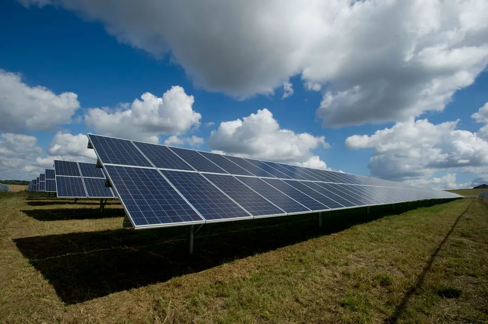
· In snowy areas, the installation angle should be adjusted to over 35 degrees to utilize gravity so that 80% of the snow slides off naturally before forming an ice layer.
· The use of snow melting agents is strictly prohibited because their pH value usually deviates from 7.0, which will corrode the 20-micron thick anodized aluminum frame.
Heat Sensitivity
When the summer ambient temperature rises above 35 degrees Celsius, the operating temperature (NOCT) of monocrystalline silicon modules under full sunlight usually reaches 65 to 75 degrees Celsius.
Due to its negative temperature coefficient, for every 1 degree Celsius increase, the output power will shrink by 0.35% to 0.42%. At a high temperature of 75 degrees Celsius, the actual power of a module rated at 550W is only about 450W, a system efficiency loss as high as 18%.
High temperatures also accelerate the aging speed of the encapsulation material EVA (Ethylene-Vinyl Acetate copolymer). In sultry environments with humidity exceeding 85%, water permeability will increase by 2 times, leading to Potential Induced Degradation (PID) inside the modules, causing the annual decay rate after 3 years of operation to soar from the normal 0.5% to over 2%.
· There must be at least a 10 cm ventilation gap between the module backplane and the roof. This can utilize convective heat exchange to reduce the module operating temperature by 5 to 8 degrees Celsius.
· During periods when the temperature is higher than 38 degrees Celsius, any form of live plugging and unplugging operations is strictly prohibited because the air ionization intensity increases and the probability of generating a 2000-degree Celsius DC arc rises by 30%.
· During the thunderstorm season, focus on checking the status of Surge Protective Devices (SPD) to ensure that the impulse grounding resistance of the grounding electrode is less than 10 ohms to prevent induced lightning overvoltage.
· Heavy rain with an intensity exceeding 50 mm/hour will wash away the surface anti-reflective (AR) coating. If the coating thickness is thinned by 5 nanometers, the visible light reflectivity will rise from 2% to over 4%.
· 13:00 to 15:00 in the summer afternoon is the period of highest hotspot risk. String current fluctuations must be monitored through software; a deviation exceeding 0.5 Amps requires immediate inspection for hidden obstructions.
Wind Load
When wind speed reaches 30 m/s (approx. level 11 wind), the dynamic lift on the module surface can reach 2400 Pa.
Long-term exposure to this vibration environment, combined with the fact that monocrystalline silicon wafers are only 160 to 180 microns thick, makes it extremely easy to cause metal grid line breakage or solder ribbon loosening. This leads to the module series resistance slowly growing from 0.5 ohms to over 1.2 ohms.
This invisible physical damage cannot be identified by the naked eye in the early stages, but it will result in a power loss in the modules within five years, which is 10% to 15% higher than normal levels.
· Every six months, a torque wrench must be used to calibrate 100% of the bolts in the bracket system to ensure that the pre-tightening torque of M8 bolts is maintained at 18 Nm.
· In windy areas, the coverage area of the module frame pressure block must reach 40 mm x 20 mm to prevent high-frequency vibration from causing 0.1 mm level chipping at the glass edges.
· Poplar and willow catkins or pollen floating in the air will form an organic coverage layer about 0.05 mm thick during dry seasons. This substance will adhere when encountering 10% relative humidity fluctuations, causing light transmittance to drop by 6%.
· Every March and October, the settlement of the bracket base must be checked. If the displacement exceeds 5 mm, it will lead to uneven mechanical stress distribution on the modules.
· For systems installed in coastal areas (within 500 meters of the coastline), C4 or C5 grade anti-corrosion coatings must be monitored to prevent salt spray corrosion from leading to grounding continuity failure.
Humidity Impacts
When the relative humidity remains above 90% for a long time, the sealing ring of the MC4 connector will age due to moisture molecule penetration, causing contact resistance to increase from 0.3 milliohms to more than 5 milliohms.
This increase in resistance will trigger local thermal effects, causing a voltage drop loss of 0.5% to 1.0% at the joint.
More dangerously, moisture will enter the combiner box through capillary action along the cable core, causing the insulation resistance to ground on the DC side to drop sharply to below 100 kΩ, triggering an insulation fault shutdown of the inverter.
· Insulation testers should sample at times of highest humidity (such as 6:00 AM) to ensure the system's resistance to ground is greater than 1 MΩ per kV.
· The design of drainage holes must ensure 100% of the bottom edge of the modules does not accumulate water. If the water accumulation belt width exceeds 5 mm, the failure speed of the silicone encapsulation will accelerate by 5 times.
· Check whether the bending radius of the DC cable is greater than 10 times the outer diameter to prevent micro-cracks from evolving into leakage points in humid air.
· In environments where salt spray concentration exceeds 0.05 mg/m³, the bracket and junction box shells must be rinsed with fresh water annually to reduce surface ionization risk by 70%.
· The humidity in the inverter room should be controlled below 65% through dehumidification equipment to prevent 0.01 mm thick chemical migration short circuits on circuit board solder joints.