A bifacial module can develop a hot spot even when the front side is completely clear. In the field, the first things to check are the parts behind the module: rails, torque tubes, cables, dirt, vegetation and uneven ground reflection. If the hot area stays on the same cell after those conditions change, the problem is more likely inside the module, such as a crack, shunt, high-resistance connection, PID or bypass-diode fault. A repeated ΔT above about 20 K deserves closer investigation, especially when the module is operating under high irradiance.[1]
Check Whether Rear Irradiance Is Actually Uneven
A clean front surface does not mean every cell is receiving the same total amount of usable light. Bifacial cells also use rear irradiance, so two cells with identical front conditions can still operate differently.
Take two cells that both receive 1,000 W/m² from the front. Their usable rear contribution is different:
| Cell | Front Contribution | Rear Contribution | Approx. Total |
|---|---|---|---|
| Cell A | 1,000 W/m² | 120 W/m² | 1,120 W/m² |
| Cell B | 1,000 W/m² | 40 W/m² | 1,040 W/m² |
The difference is about 80 W/m², or roughly 7%. Neither cell is shaded on the front, but the two cells are no longer producing under the same light conditions.
The figures above are simplified because rear response depends on bifaciality. Tongwei's TNC-G12R bifacial cell data provides model-specific electrical characteristics rather than assuming equal front and rear response.
NREL has used approximately 1,000 W/m² front irradiance with 130-140 W/m² rear irradiance in bifacial reference-condition studies.[2] Real sites are less tidy. Racking, ground cover, row position and mounting height can all make the rear side more uneven.
A 5-10% local difference usually shows up first as mismatch loss, not as an immediate dangerous hot spot. If the thermal difference is already large, there is often another factor involved, such as a weak cell, a poor connection or a more severe local irradiance drop.
Match the Hot Cells to Rails and Torque Tubes
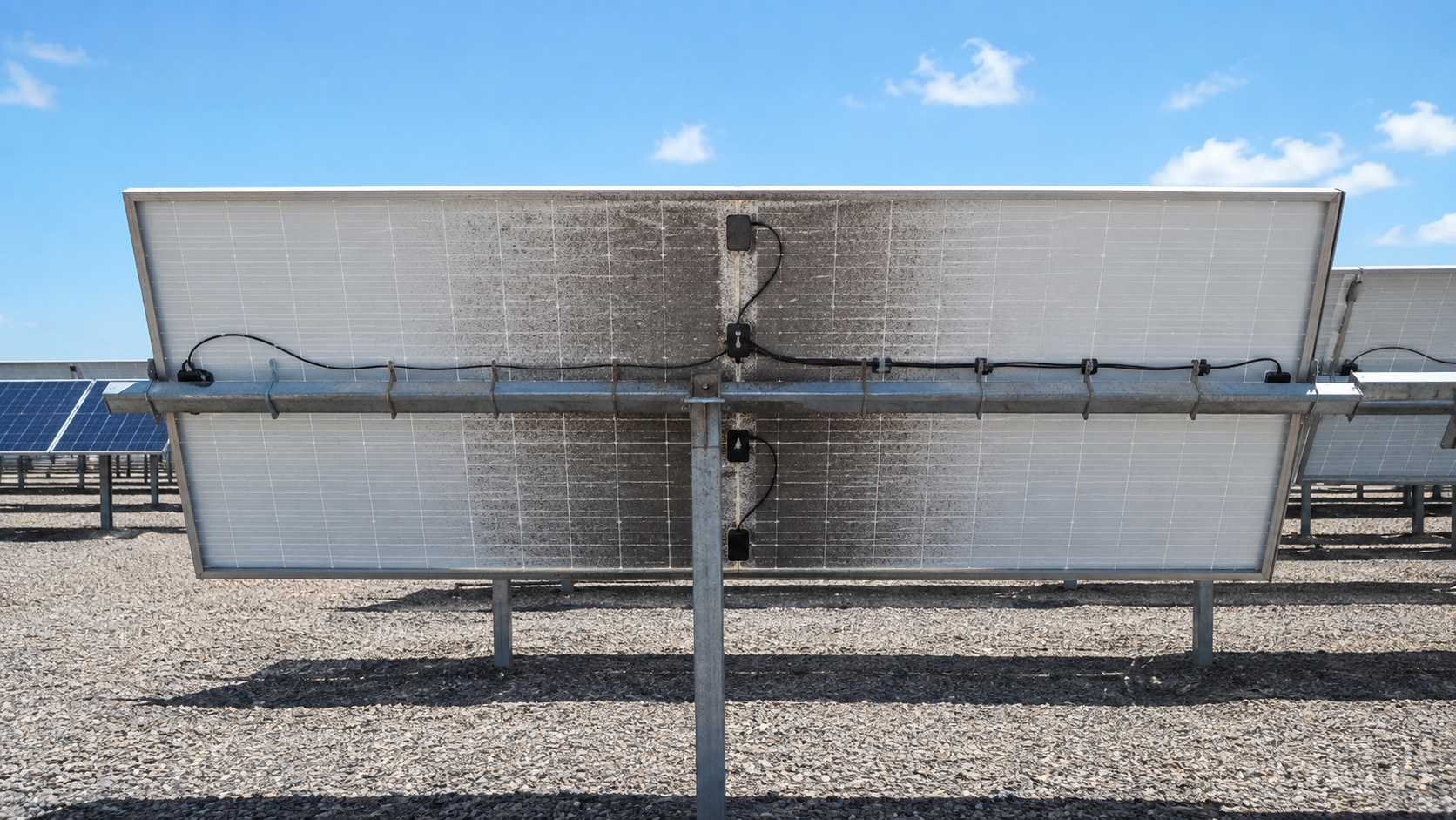
Before treating a hot cell as a module defect, line up the IR image with the hardware behind the module. Rails, clamps, tracker beams, torque tubes, cable trays, junction-box wiring and loose cable bundles can all reduce rear light.
- rails;
- clamps;
- tracker beams;
- torque tubes;
- cable trays;
- junction-box wiring;
- loose cable bundles.
How close the hardware sits to the glass matters. A 40 mm-wide member only 30 mm behind the module blocks a much larger viewing angle than the same 40 mm member positioned 200 mm away.
That small distance change can make a narrow part appear optically much more significant than its physical width suggests.
The easiest clue is repetition. If 10, 20, or more modules show hotter cells in the same place above the same rail or torque tube, it makes little sense to treat them as 20 unrelated cell failures. The racking layout should be checked first.
Torque tubes add another variable because tracker angle changes throughout the day. NREL research has shown that torque-tube geometry can affect rear irradiance and rear-shading loss in bifacial tracker systems.[3]
Repeat the IR inspection at another tracker angle. If the pattern changes with the tube position, rear-light geometry is likely involved. If the same physical cell stays hot, the next step should be electrical testing.
Look for Sharp Rear-Irradiance Changes
For hot-spot diagnosis, average ground albedo is often less useful than what is happening directly below neighboring cells.
One part of a module table may see:
- one cell area receives about 180 W/m² from the rear;
- an adjacent area behind a beam receives 80-100 W/m²;
- another edge area may receive more because it sees a larger bright-ground area.
These are example values, not fixed limits. What matters is that the change happens over a small area instead of gradually across the whole table.
Typical places to look for this kind of sharp change include:
- snow beside exposed soil;
- light gravel beside wet dark soil;
- a puddle below only part of a module;
- a beam crossing one cell area;
- heavy vegetation below the lower cells.
Module height also changes the rear-light pattern. A lower module sees a smaller area of the ground, so nearby structures and shadows take up a larger part of its rear field of view. NREL measurements confirm that height, row spacing, tilt and albedo affect bifacial rear irradiance.[4]
Remove Cables, Dirt and Vegetation Before Electrical Testing
If there is an obvious rear obstruction, remove that variable before moving straight to EL testing or module replacement.
Check for:
- grass or weeds reaching the rear glass;
- DC cables hanging across active cell areas;
- bird droppings;
- mud;
- leaves;
- cable bundles;
- labels or material added after installation.
A simple before-and-after check is usually more useful than guessing:
- record the original IR pattern and ΔT;
- remove the obstruction safely;
- allow the module to return to stable operation;
- repeat the IR image under similar irradiance and wind;
- compare the exact same cell.
If a cell is 18 K hotter before cleaning and only 4 K hotter afterward, the obstruction clearly affected the thermal pattern. If it remains around 18 K, the cause is not explained by cleaning alone and electrical diagnosis should continue.
Check the Module Circuit Before Blaming One Cell
The same rear shadow can produce different results on different module designs. Internal wiring decides how far the mismatch spreads.
Modern modules can use:
- full cells;
- half-cut cells;
- parallel current branches;
- several substrings;
- multiple bypass diodes.
A bypass diode usually protects a substring, not one individual cell. Half-cut modules can also divide current between branches, so a local problem may affect only one part of the module instead of pulling down every cell in the same way.
That difference shows up in several places:
- cell current;
- reverse voltage;
- bypass-diode operation;
- I-V curve shape;
- temperature pattern;
- total power loss.
Use the exact module documentation instead of assuming every bifacial product has the same circuit. Tongwei's module range and technical downloads can be used to check model-specific electrical specifications.
Suspect a Crack When the Same Cell Stays Hot
A cell crack moves higher on the suspect list when the same cell stays hot after the easy external causes have been ruled out.
- the same cell stays hot after cleaning;
- the pattern does not move with tracker angle;
- neighboring modules are normal;
- no rail or cable matches the hot area;
- EL shows an electrically inactive region.
Crack length by itself tells you very little. The more important question is whether the crack breaks a useful current path or electrically isolates part of the cell.
A long crack can still leave enough conductive routes for the cell to work normally. A shorter crack in the wrong place can cut through a critical collection path and create a much larger electrical problem.
IEA PVPS lists cracked and damaged cells among recognized hot-spot causes.[5]
The outside of the module may still look normal. Tongwei's module reliability discussion also covers failures that may not be obvious during a normal visual inspection.
Use I²R to Check High-Resistance Connections
Uniform light does not rule out a hot electrical connection. A weak solder joint, ribbon, busbar or junction-box connection can heat because of resistance.
The relationship is straightforward:
P = I²R
If current increases by 20% and resistance stays the same:
1.2² = 1.44
The resistive heating increases by about 44%.
Using the same calculation:
- initial connection heating: 2.0 W;
- current increase: 20%;
- new heating: about 2.88 W.
This matters on bifacial modules because useful rear irradiance can raise operating current. The rear light did not create the weak joint, but it can make that weak joint run hotter and show up more clearly in an IR image.
IEA PVPS identifies failed solder bonds and interconnections as causes of local heating and increased resistance.[6]
Separate a Shunt From Full-Cell Heating
A tiny fixed hot point should not be treated the same way as an entire warm cell.
A shunt is an unwanted low-resistance path through part of the cell. Current becomes concentrated in that small area, so the IR image can show a point-like hot spot instead of full-cell heating.
A shunt becomes more likely when:
- the hot area is much smaller than the cell;
- it stays in exactly the same position;
- changing rear-light geometry does not move it;
- cleaning has no effect.
If the whole cell is hot instead, strong mismatch, reverse bias or a larger electrically damaged region should be checked first.
Calculate How Reverse Bias Creates Heat
When one cell cannot supply the current required by its series path, its voltage can fall below zero. At that point the cell is absorbing electrical power rather than helping produce it.
The heat can be estimated with:
heat ≈ current × absolute reverse voltage
For illustration:
10 A × 1 V = 10 W
If the cell carries 10 A while operating at -1 V, about 10 W is being dissipated at that cell. This is an example, not a standard hot-spot value. Actual current and reverse voltage depend on the module and the fault.
What matters in practice is where that heat is concentrated. Ten watts spread over a full module is one thing; 10 W concentrated in one thin cell is very different. The local temperature can become high even while string power still looks fairly normal.
IEA PVPS describes reverse bias, junction breakdown, damaged cell contacts and increased connection resistance as mechanisms behind localized module heating.[7]
Check the Bypass Diode When a Substring Is Abnormal
A bypass diode does not react to every weak cell immediately. It normally protects a whole substring, so one cell can already be in reverse bias before the substring voltage is low enough to turn the diode on.
| Diode Condition | Likely Result |
|---|---|
| Normal diode | Bypasses the substring during sufficiently severe mismatch |
| Open-circuit diode | No bypass path; reverse-bias stress can become worse |
| Short-circuit diode | Substring remains bypassed; module voltage and power fall |
IEA PVPS identifies both open- and short-circuit bypass-diode faults.[8]
A junction box that is much hotter than the same component on neighboring modules deserves its own electrical check. Do not label it as rear-side cell shading without confirming the diode and connection condition.
Check PID When Several Cells Follow a Pattern
PID is less likely to look like one tiny isolated point. It usually becomes more relevant when several cells or repeated string positions show a pattern.
Useful clues include:
- multiple warm cells;
- cells near the module edge behaving differently;
- a patchwork thermal pattern;
- similar abnormalities at particular string positions;
- reduced fill factor;
- lower module or string power.
PID is related to high electrical potential relative to ground and leakage mechanisms inside the module. IEA PVPS lists IR, EL and electrical testing among the methods used to identify it.[9]
One isolated hot cell by itself is not enough evidence to call the problem PID.
Use the IR Shape to Choose the Next Test
| IR Result | Most Useful Suspects | Next Test |
|---|---|---|
| One full cell hot | Reverse bias, crack, strong mismatch | Rear inspection, I-V, EL |
| Part of one cell hot | Crack, shunt, local resistance | EL and electrical testing |
| Small fixed hot point | Shunt or local breakdown | Cell-level electrical check |
| Cells line up with a rail | Rear structural shading | Compare other modules at the same rail position |
| Pattern moves with tracker angle | Torque tube or rear-light geometry | Repeat IR at another angle |
| Hot region matches dirt or vegetation | Local rear obstruction | Remove and retest |
| Narrow hot line | Ribbon or solder resistance | Connection testing |
| One substring differs | Strong mismatch or bypass-diode activity | I-V and diode testing |
| Junction box is very hot | Diode or connection fault | Qualified electrical inspection |
| Several edge cells are warm | PID or systematic rear irradiance | EL, I-V and neighboring-module comparison |
IR shape is useful for narrowing the list, but it cannot confirm the root cause on its own. IEA PVPS also uses the location and shape of thermal abnormalities together with electrical or imaging tests.[10]
Use ΔT Instead of Absolute Module Temperature
A module at 70°C is not automatically faulty. The useful number is the difference between the suspicious area and a comparable nearby cell under the same conditions.
| Nearby Cell | Hot Cell | ΔT | What to Do |
|---|---|---|---|
| 55°C | 58°C | 3 K | Usually small; verify conditions before investigating further |
| 55°C | 70°C | 15 K | Check whether it is stable and whether power is affected |
| 55°C | 82°C | 27 K | Investigate the electrical or optical cause |
IEA PVPS treats a temperature gradient below 10 K as normal. A stable 10-20 K difference is described as unproblematic when it does not increase during operation. A gradient above 20 K deserves more attention because power loss and material damage become more likely.[11]
Do not turn 20 K into an automatic replacement rule. Wind, irradiance, current and the type of fault can all change the measured ΔT.
Do Not Estimate Power Loss From Temperature Alone
A very hot cell does not always mean a large percentage loss in module power.
Take a 600 W module with 2% output loss:
600 W × 2% = 12 W
At module level, 12 W may not look serious in monitoring data. If several watts of that loss are concentrated in one small damaged cell region, however, local temperature can still become high.
The reverse can also happen. Broad degradation may reduce output without producing one dramatic hot point.
Keep these three checks separate:
- ΔT;
- electrical power loss;
- material or safety damage.
Take IR Images Under Useful Conditions
An IR image taken under weak or unstable conditions can hide the problem or make two modules look different for the wrong reason.
- Keep the PV system operating under load.
- Use stable, strong sunlight where possible.
- Avoid fast-moving clouds.
- Avoid strong or rapidly changing wind.
- Compare modules at similar tracker angles.
- Change camera angle to rule out glass reflections.
IEA PVPS recommends irradiance above about 800 W/m² for meaningful field thermography and specifies that the PV system should be operating during the measurement.[12]
At 300-400 W/m², module current is normally much lower than under 800-1,000 W/m² conditions. Some resistance-related or reverse-bias heating can therefore be harder to see.
IEC TS 62446-3 gives requirements for outdoor PV thermography, including test conditions, equipment and reporting.[13]
Do Not Trust One Rear Irradiance Sensor
A rear sensor tells you what is happening at that sensor. It does not tell you what every cell on the table is seeing.
For example:
- rear sensor: 180 W/m²;
- cell behind a rail: 100 W/m²;
- edge cell: 220 W/m².
These are illustrative values. A sensor can correctly report 180 W/m² while one nearby cell sees much less light and an edge cell sees more.
NREL has specifically studied rear-irradiance nonuniformity, row position and rear-sensor location in bifacial arrays.[14]
Use IR, I-V and EL for Different Jobs
| Test | What It Shows Best |
|---|---|
| IR | Where abnormal heat appears during operation |
| Daylight I-V | Mismatch, bypass activity, resistance and power loss |
| EL | Cracks, inactive cell regions and broken current paths |
Bifacial I-V testing also has to account for rear illumination. IEC TS 60904-1-2 covers additional requirements for bifacial current-voltage measurement.[15]
EL is most useful when the same cell stays hot after cleaning and after rear geometry changes. A crack visible in EL only matters to this diagnosis if it changes current flow or leaves part of the cell inactive.
Tongwei's EL testing discussion also shows why EL works best when it is used together with thermal and electrical testing.
Follow This Fault-Checking Order
- Verify the IR image. Change the camera angle and rule out reflections.
- Check the rear surface. Look for rails, tubes, cables, dirt and vegetation.
- Compare nearby modules. Repeated patterns usually point to layout; one isolated cell points toward a module fault.
- Remove temporary obstructions. Clean or clear them and repeat IR.
- Change tracker angle. See whether the pattern moves with rear geometry.
- Compare current, voltage and power.
- Run daylight I-V. Look for mismatch, bypass activity or high resistance.
- Use EL. Check suspected cracks or inactive regions.
- Check the junction box and bypass diodes when a substring or junction-box pattern appears.
Replace the Module Only After the Cause Is Confirmed
Vegetation, dirt or a loose cable can create a thermal difference without meaning the module itself has failed.
One case could look like this:
- ΔT = 5 K before vegetation removal;
- ΔT falls close to normal after removal;
- no abnormal I-V behavior is found.
That is a maintenance problem.
A more serious case looks different:
- the same cell remains 25-30 K above neighboring cells;
- the result repeats under stable conditions;
- cleaning and tracker-angle changes do not remove it;
- I-V or EL shows an electrical defect.
That needs deeper technical assessment.
Burn marks, melted junction-box parts, damaged insulation, arcing evidence or severe repeated overheating require prompt qualified inspection. IEA PVPS recommends repair or replacement when the module presents a direct safety risk.[16]
Prevent Repeat Hot Spots With Baseline Data
When the plant is commissioned, save IR images while the array is known to be operating normally. Keep the module position, tracker angle, irradiance and ΔT with those records.
Later inspections can then be compared with the same physical locations. That is much more useful than judging every module against one generic temperature number.
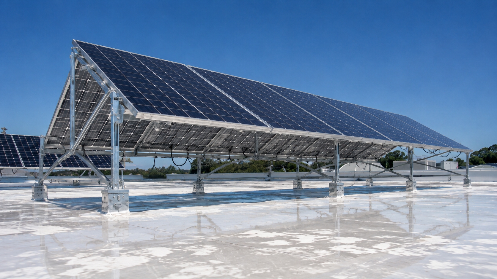
Racking, torque-tube position, ground clearance and cable routing should also be checked when reviewing bifacial system performance. Use model-specific limits from the current module technical documentation instead of applying one generic rule to every bifacial product.
FAQ
Can rear shading alone cause a hot spot?
Yes, but mild rear nonuniformity usually causes mismatch loss first. Severe heating becomes more likely when the rear difference is sharp, module current is high, or the affected cell already has a crack, shunt or weak connection.
Why does the hot spot appear only in the afternoon?
Tracker angle, structural shading, ground reflection and current change during the day. If the pattern changes with tracker angle, rear geometry is likely involved. If the same cell stays hot, investigate an electrical defect.
Is a 10 K temperature difference dangerous?
Not automatically. IEA PVPS treats less than 10 K as a normal gradient and stable 10-20 K differences as generally unproblematic. Persistent values above 20 K deserve more attention, especially when electrical loss or material damage is also present.
Can one hot cell cause only a small power loss?
Yes. A small damaged region can run very hot while the rest of the module continues producing power. For example, 2% loss from a 600 W module is only 12 W at module level, but several watts concentrated in one small cell region can still create a serious thermal problem.
Finally
If there is no front shade, start with what can actually change from one cell to the next: rear rails, torque tubes, cables, vegetation, dirt and local ground reflection. Retest after removing temporary obstructions and, on trackers, at another angle. For field IR work, around 800 W/m² or higher irradiance gives a more useful result. A stable ΔT below 20 K is less concerning than a persistent value above 20 K, but temperature alone is not enough to condemn a module. If the same cell remains hot after the rear-light conditions change, use I-V and EL to check for a crack, shunt, resistive connection, PID or bypass-diode fault.