Yes. Hidden mismatch can show up after old modules are replaced with newer ones, even when the inverter keeps running and no fault appears. The problem usually starts when the replacement modules have different current, voltage, temperature behavior, or shading response from the modules already on site.
The biggest risks are mixed modules in one series string, different strings sharing one MPPT, higher-current modules connected to older DC equipment, and old string lengths reused after Voc or Vmp has changed.[1]
Check These Five Ratings
When comparing a replacement module with the original one, start with Pmax, Vmp, Imp, Voc, and Isc. Wattage alone does not tell you whether the two modules will work well in the same electrical system.
| Parameter | Old Module | New Module | Change |
|---|---|---|---|
| Pmax | 300 W | 450 W | +50% |
| Vmp | 32 V | 34 V | +6.25% |
| Imp | 9.4 A | 13.2 A | +40.4% |
| Voc | 40 V | 41 V | +2.5% |
| Isc | 10.0 A | 14.0 A | +40% |
The numbers show the problem clearly. Rated power rises by 50%, but operating voltage rises only 6.25%. Operating current rises about 40.4%. In electrical terms, the new module is not simply a 50% larger version of the old one.
Vmp and Imp tell you how the module behaves around its maximum-power point. Voc and Isc become especially important when you check voltage limits, current limits, protection, and other equipment.
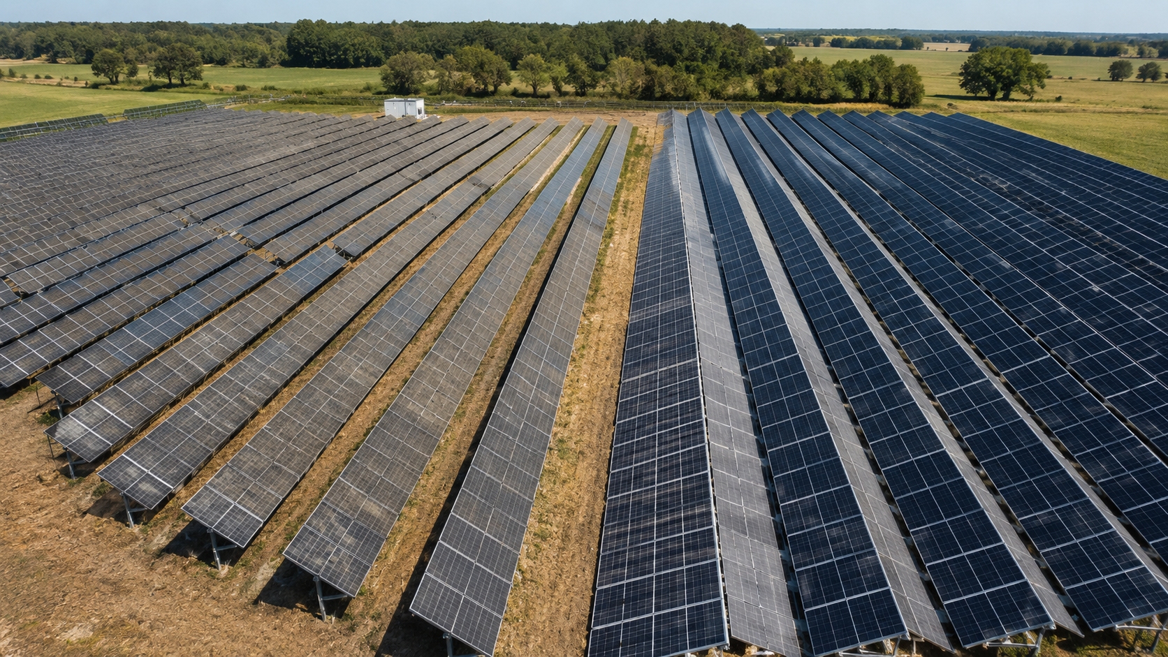
These ratings are normally stated at Standard Test Conditions, commonly 1,000 W/m² irradiance and 25°C cell temperature. A module in the field will not stay at those conditions, so its actual voltage, current, and power vary with sunlight and cell temperature.[2]
You can see the same pattern in current module data. Tongwei's module specifications for different application scenarios, for example, include a 455 W module with 30.44 V Vmp, 14.95 A Imp, 35.95 V Voc, and 15.98 A Isc at STC. Those figures are very different from many older modules designed around lower string current.
Watch Current in Mixed Strings
Take a 20-module string with nineteen older modules at about 9.4 A Imp. One damaged module is replaced with a newer module rated at 13.2 A Imp.
| String Position | Imp | Difference |
|---|---|---|
| 19 old modules | 9.4 A | — |
| 1 new module | 13.2 A | +3.8 A / +40.4% |
The new module is designed to deliver 3.8 A more current at its own maximum-power point. The string, however, does not let each module choose its own current. All series-connected modules carry the same string current. Sandia identifies this shared-current behavior as one of the basic causes of PV mismatch.[3]
The 450 W module reaches its rated power around 34 V and 13.2 A. Put it into a string operating much closer to 9.4 A and it moves away from that point on its I-V curve.
One shortcut to avoid is this:
34 V × 9.4 A = 319.6 W
The arithmetic is correct, but that is not a reliable way to calculate the module's real output. At 9.4 A, the module does not necessarily stay at 34 V. Its voltage also changes along the I-V curve.
Actual output depends on the full I-V curve, sunlight, cell temperature, the other modules in the string, and the operating point chosen by the inverter.
In practice, the replacement module may appear to work normally while part of the extra current capability behind its 450 W rating remains unused.
Avoid Low-Current Bottlenecks
Now reverse the mix: nineteen modules are designed to operate near 13.2 A, while one older module is around 9.4 A.
The difference is still 3.8 A, but the situation is different. The lower-current module now sits inside a string that wants to run at a much higher current.
As string current rises, the older module can be pushed into another part of its I-V curve. Its voltage may fall. If part of the module can no longer support the string current, a bypass diode may conduct around a cell substring. The string stays online, but part of that module's voltage is lost.
Typical field clues include:
- steps in the I-V curve;
- multiple peaks in the power curve;
- lower string voltage under certain conditions;
- uneven module temperature;
- performance loss that becomes stronger under partial shade.
IEA PVPS documents how bypass-diode layout and nonuniform operating conditions can change PV output and create more complex operating points.[4]
Do Not Share One MPPT Blindly
Keeping old and new modules in separate strings helps, but it does not remove mismatch if both strings are connected to the same MPPT.
| String | Configuration | Nominal Vmp |
|---|---|---|
| String A | 20 × 32 V | 640 V |
| String B | 18 × 34 V | 612 V |
The nominal difference is 28 V, or about 4.4% relative to the 640 V string.
Once both strings share one MPPT, they also share one operating voltage at the connection point. The inverter cannot keep String A at 640 V and String B at 612 V at the same time. It has to choose a voltage for the combined power curve.[5]
That does not mean a 4.4% voltage difference creates a 4.4% energy loss. The actual loss depends on the shape of each P-V curve, string power, irradiance, temperature, shading, and MPPT behavior.
For a repowering decision, being inside the inverter's allowed MPPT range is only the first check. Two strings can both be within the allowed range and still work poorly together on one tracker.
Compare Voltage and Current, Not Watts
Modules with the same wattage can still be very different electrically.
| Parameter | Module A | Module B | Difference |
|---|---|---|---|
| Pmax | 400 W | 400 W | 0% |
| Vmp | 40 V | 32 V | Module A +25% |
| Imp | 10 A | 12.5 A | Module B +25% |
Both modules are 400 W. Module A uses 25% more voltage, while Module B uses 25% more current.
For replacement work, compare:
- Pmax;
- Vmp;
- Imp;
- Voc;
- Isc;
- Voc temperature coefficient;
- power or Vmp temperature coefficient;
- cell and substring layout;
- bypass-diode arrangement;
- connector type;
- maximum system voltage.
Current module technical data should be checked model by model rather than assuming similar wattage means similar electrical behavior.
Measure Old Modules Again
A 10- or 15-year-old module may no longer match the electrical behavior shown on its original datasheet.
Common field problems include:
- cell cracks;
- connection damage;
- encapsulant or backsheet degradation;
- potential-induced degradation;
- bypass-diode faults;
- hot spots;
- connector damage.
IEA PVPS' 2025 degradation report covers several of these failure modes, including cell cracking, PID, polymer degradation, thin-glass failure, and bypass-diode connection problems.[6]
Aging also does not reduce every electrical parameter by the same amount. One fault may mainly reduce current. Another may reduce voltage or change the shape of the I-V curve.
That means two old modules can both measure 280 W and still behave differently when placed in the same electrical group as new modules.
For older arrays, current field data matters when assessing PV module degradation. Useful evidence includes string current, representative I-V traces, thermal inspection, and historical monitoring data.
IEC 61215 qualification shows whether a module design can withstand defined environmental stresses. It does not tell you the exact remaining output or lifetime of an individual module that has already spent years in the field.[7]
Recalculate Cold Voc
Keeping the same number of modules does not guarantee that the new string will stay inside the old voltage limit.
Assume:
- Voc at STC = 41 V;
- Voc temperature coefficient = -0.28%/°C;
- reference cell temperature = 25°C;
- example cold cell temperature = -10°C.
| Step | Calculation | Result |
|---|---|---|
| Temperature change | 25 - (-10) | 35°C |
| Voc increase | 35 × 0.28% | 9.8% |
| Cold module Voc | 41 × 1.098 | ≈45.0 V |
| 22-module string at STC Voc | 22 × 41 | 902 V |
| 22-module cold Voc | 22 × 45.0 | ≈990 V |
The same 22-module string rises by about 88 V, or 9.8%, in this simplified example.
If the inverter or other DC equipment has a 1,000 V maximum input limit, a calculated value near 990 V leaves very little room for design assumptions or parameter differences. The project calculation therefore needs the actual manufacturer coefficient and the required site design temperature, not this example alone.
IEC 62548-1 covers PV array design requirements for DC wiring, protection, switching, earthing, and interfaces with power-conversion equipment.[8]
Check Hot-Weather Vmp
The cold-voltage check is only half of the job. High cell temperature normally pushes operating voltage down.
| Inverter Value | What It Controls |
|---|---|
| Startup voltage | Whether the inverter can begin operating |
| MPPT voltage range | Where maximum-power tracking is designed to operate |
| Maximum DC voltage | The upper equipment limit |
A replacement string can pass the cold-Voc check and still have a poor hot-weather operating voltage. This is more likely when the replacement module has a lower Vmp, a different temperature coefficient, or a different number of modules per string.
Recheck Current Limits
For many modern replacements, current changes more sharply than voltage.
| Parameter | Older Module | Newer Module | Increase |
|---|---|---|---|
| Imp | 8.8 A | 13.5 A | +4.7 A / +53.4% |
| Isc | 9.4 A | 14.2 A | +4.8 A / +51.1% |
A roughly 53% increase in operating current can affect much more than the inverter itself.
Check:
- current per MPPT;
- current per physical inverter input;
- maximum short-circuit current;
- allowed parallel string count;
- string conductors;
- homerun conductors;
- combiner boxes;
- fuses;
- DC disconnects;
- terminals;
- connectors.
IEC 62548-1 treats DC wiring and protection as part of array design, so the inverter's total DC wattage rating alone is not enough.[9]
Tongwei's current module data includes utility-scale products with Imp above 17 A. A DC system originally built around modules operating below 10 A can therefore face a major current increase even if string voltage still looks manageable.
Connectors deserve the same level of checking. Two PV connectors may look compatible and still not be an approved mating pair. Connector type, ratings, assembly instructions, and manufacturer requirements need to match. IEC 62852 covers safety requirements and tests for DC connectors used in PV systems.[10]
Separate Old and New MPPTs
If the inverter has independent MPPTs, separating electrically different strings is often the cleaner layout.
| Layout | Result |
|---|---|
| Old + new strings on one MPPT | Both groups must share one operating voltage |
| Old strings on MPPT 1, new strings on MPPT 2 | Each group can be tracked at a different voltage |
One practical detail causes plenty of mistakes: not every physical DC connector is its own MPPT. Some inverters place several connector pairs under one tracker. The inverter's electrical diagram should show the real grouping.
Power optimizers can reduce some module-level mismatch, but optimizer voltage, current, Isc, power, and string limits still apply. Microinverters largely avoid conventional long-string module mismatch because each module has its own conversion input, but the module still has to stay within the microinverter's electrical limits.
IEA PVPS also notes that module-level electronics have their own conversion losses, so they should not automatically be assumed to increase energy in every shaded system.[11]
Rebuild String Length
Do not carry the original module count into the new design without recalculating it.
| Configuration | Calculation | Nominal Vmp |
|---|---|---|
| Original string | 20 × 32 V | 640 V |
| 20 replacement modules | 20 × 40 V | 800 V |
| 16 replacement modules | 16 × 40 V | 640 V |
Keeping 20 modules raises nominal string Vmp by 160 V, or 25%.
Sixteen replacement modules happen to return nominal Vmp to 640 V in this simplified example. That still does not make 16 the final engineering answer.
The final string has to pass:
- cold Voc;
- hot Vmp;
- startup voltage;
- MPPT range;
- current limits;
- Isc limits;
- power limits;
- protection requirements.
Check Shade by Module Layout
Old and new modules can react differently to the same shadow even when their Vmp and Imp look reasonably close.
Compare:
- full-cell versus half-cell design;
- cell dimensions;
- substring arrangement;
- bypass-diode layout;
- module dimensions and orientation.
A roof vent, parapet, pole, tree, cable tray, or row edge may cover different electrical sections of old and new modules. Once a bypass diode conducts, part of the affected module's voltage drops out of the string.
Moving a replacement module from one end of the string to the other does not remove the shared-current issue. Position matters only when it changes the real shade, temperature, rear irradiance, or wiring conditions seen by that module.
Model Bifacial Rear Gain
Bifacial repowering adds another current variable: rear-side irradiance.
Rear irradiance varies with:
- ground or roof reflectance;
- module height;
- row spacing;
- tracker position;
- racking beams;
- cable trays;
- vegetation;
- rear-side shade.
Uneven rear irradiance changes module current. Sandia field research found that nonuniform rear irradiance can produce mismatch and stepped I-V curves in bifacial strings.[12]
The Tongwei TWMNF-66QD, for example, lists mass-production bifaciality of 90±5%. High bifaciality makes rear-side conditions more important, but it does not mean every module receives 90% extra energy. Actual rear contribution still depends on the installation environment.
Rule Out Other Losses
If a repowered plant misses its target, do not assume mismatch is the cause before checking the other usual losses.
| Metric | Result |
|---|---|
| Pre-repowering annual output | 500 MWh |
| Expected post-repowering output | 560 MWh |
| Expected gain | 60 MWh |
| Measured post-repowering output | 535 MWh |
| Measured gain | 35 MWh |
| Expected gain achieved | 58.3% |
| Expected gain not achieved | 25 MWh / 41.7% |
Only about 58% of the modeled gain was achieved, but the missing 25 MWh could come from several places:
- string mismatch;
- MPPT mismatch;
- inverter clipping;
- shade;
- soiling;
- curtailment;
- export limits;
- failed or unavailable strings;
- wiring loss;
- temperature differences;
- incorrect modeling;
- sensor error.
Mismatch means modules or strings are being pushed away from their preferred electrical operating points. Clipping means available DC power is higher than an inverter or output limit. Curtailment means output is being intentionally reduced.
The causes of PV module mismatch also show why there is no reliable shortcut such as “10% current difference equals 10% annual energy loss.”
Use These Failure Clues
| What You See | Check First |
|---|---|
| One MPPT is consistently lower than a similar MPPT | String types, Vmp, current, orientation, shade |
| One similar string has lower current | Modules, connectors, fuses, wiring, shade |
| Loss occurs at the same time on sunny days | Fixed or moving shade |
| AC power repeatedly reaches a flat ceiling | Inverter clipping or output limit |
| Controller shows a lower power setpoint | Curtailment or export control |
| Performance worsens mainly in high heat | Hot Vmp and MPPT range |
| I-V curve contains steps | Shade, bypass diodes, mixed module behavior |
| Unexpected cold-weather voltage | Voc calculation and string length |
Verify the Array
Start with inverter data. Compare voltage, current, DC power, MPPT channel, irradiance, temperature, and any power-limit status.
Compare like with like. Strings should have the same module type, string length, orientation, and similar sunlight before their current values are compared directly.
Use I-V tracing when needed. Reduced current, lower voltage, curve steps, or an unusual knee can help separate shading, bypass operation, degradation, and mismatch. Irradiance and temperature need to be recorded with the trace.
NREL uses controlled measurement conditions for high-precision PV module and cell performance testing because electrical comparisons only make sense when the test conditions are known.[13]
Use thermal inspection to find where to look. Hot cells, substrings, connectors, or diode areas can point to the part of the array that needs more checking, but a thermal image alone does not prove the cause.
Normalize historical comparisons. Raw annual kWh from two different years can be misleading if irradiance, temperature, downtime, or curtailment changed. Sandia's normalized performance guidance shows why environmental conditions need to be included when PV output is compared over time.[14]
System owners can review monitoring and project records. Live DC testing, circuit disconnection, insulation testing, I-V tracing, and connector work should be carried out by qualified personnel.
Choose the Right Layout
| Repowering Layout | Main Risk | Preferred Check |
|---|---|---|
| Old and new modules in one string | Current and I-V mismatch | Imp, I-V curves, bypass behavior |
| Old and new strings on one MPPT | Different preferred voltages | Vmp and combined P-V behavior |
| Old and new strings on separate MPPTs | Lower interaction | Confirm true MPPT independence and equipment limits |
| Full string redesign | Higher design effort | Recalculate string length, current, wiring, protection, and connectors |
Redesign When Limits Move
Rebuilding the affected string or MPPT group becomes more reasonable when:
- the original module is no longer available;
- Imp or Isc rises substantially;
- Vmp or Voc changes enough to alter string sizing;
- old and new strings cannot use suitable separate MPPTs;
- field-aged modules show uneven performance;
- the inverter is near replacement age;
- new module dimensions require racking changes;
- fuses, conductors, connectors, or combiner equipment no longer fit the new current;
- the site is expected to operate for many more years.
A replacement that is electrically close to the original may need only limited redesign. A project that changes module current by 40–50%, shifts nominal string voltage by 20–25%, or forces different module generations onto one MPPT needs much closer system-level review.

Build the Electrical Map First
Before ordering replacement modules, collect these values:
| Module | Inverter / System |
|---|---|
| Pmax | Maximum DC voltage |
| Vmp | MPPT voltage range |
| Imp | Startup voltage |
| Voc | Maximum current per MPPT |
| Isc | Maximum short-circuit current |
| Voc temperature coefficient | Number of independent MPPTs |
| Power/Vmp temperature data | Allowed strings per input |
| Connector type | Fuse and conductor limits |
| Module dimensions | Existing string layout |
Use the exact module technical specifications, not only the wattage class.
Map the existing array before buying replacement modules:
- module model in each string;
- modules per string;
- strings connected in parallel;
- strings connected to each MPPT;
- physical inverter inputs sharing each MPPT;
- optimizers or other module-level electronics;
- combiner boxes;
- fuses;
- conductors;
- connector types.
Check the physical array against the original drawings. Older plants often contain module swaps, repaired strings, replacement inverters, or wiring changes that are not shown on the first as-built drawing.
After repowering, record the new string-to-MPPT map, operating voltage, current, module models, representative I-V traces where appropriate, test conditions, and expected production. These values become the baseline for future troubleshooting.
Finally
The numbers usually tell you whether a repowering plan deserves a closer look. In the examples above, moving from 300 W to 450 W raises Imp by about 40.4%, two strings differ by 28 V on one shared MPPT, a cold 22-module string rises from 902 V to about 990 V, and keeping 20 modules after Vmp moves from 32 V to 40 V raises nominal string voltage by 25%.
None of those changes should be treated as a simple module swap. Check the actual string map, Vmp, Imp, Voc, Isc, temperature limits, MPPT grouping, wiring, protection, and connectors before the replacement module is approved.