A module may still generate near-normal power after its glass breaks. This does not mean it is safe. Moisture can enter the laminate, insulation resistance can fall, and loose glass can create a falling hazard. NREL reports that recent unexplained glass failures are usually linked to several factors acting together rather than one single defect.[1]
| Item | Common or example value | Why it matters |
|---|---|---|
| Traditional glass-backsheet module | About 3.2 mm front glass | Thicker front glass was common on older module designs |
| Modern double-glass module | Often 2.0 mm + 2.0 mm or 1.6 mm + 1.6 mm | Thin glass needs good edge quality, support and handling |
| Large module area | About 2–3 m² | A larger area collects more total wind and snow force |
| Example large module weight | About 30–33 kg | Incorrect lifting can bend or twist the laminate |
| Common listed mechanical loads | 2,400 Pa wind and 5,400 Pa snow | The rating only applies to the approved mounting arrangement |
These values are examples, not universal limits. The exact product data sheet and installation manual always take priority.
How the Crack Starts
Most non-hail glass failures develop in three steps.
| Step | What happens | Examples |
|---|---|---|
| Initial damage | A weak point forms in or around the glass | Edge chip, scratch, rough cut, trapped sand or handling impact |
| Constant stress | The installed module is held in a bent or twisted position | Wrong clamp position, uneven rails or frame contact |
| Final load | An extra load makes the flaw grow into a visible crack | Wind, snow, cleaning pressure, local cooling or overheating |
These steps may happen months apart. A corner can be chipped during unloading, twisted by uneven rails during installation and finally broken during strong wind.
The event immediately before the crack appeared may only be the final trigger. An investigation should identify both the original weak point and the load that caused it to grow.
Edge Chips and Scratches
Glass strength is controlled by its weakest flaw. A small defect can be serious when it is deep, sharp or located near a clamp, corner or frame contact point.
Common flaws include:
- Chips along a cut edge
- Scratches caused during transport or framing
- Damage around holes and rear-glass openings
- Sharp corner defects
- Marks caused by clamps or metal parts
- Sand or metal trapped inside the frame
A long, shallow scratch is not always more dangerous than a short edge chip. A deep chip hidden below the aluminum frame can open quickly when the module bends.
Heat-treated glass has a compressed surface and a tensioned centre. The compressed layer helps keep small flaws closed. NREL describes the compression-zone depth as roughly 20% of the glass thickness. As a simple illustration, this is about 0.4 mm in 2.0 mm glass and about 0.64 mm in 3.2 mm glass. These are approximate values, not inspection limits.[2]
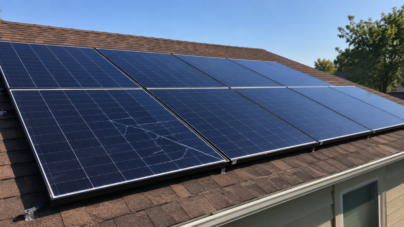
If a flaw passes through the compressed surface and reaches the inner tensioned area, it can spread under a much lower external load.
The longest visible crack is not necessarily the starting point. Look for a small area where several lines meet or spread outward, especially near:
- A corner
- A clamp
- A glass opening
- The lower edge
- A hidden frame channel
Use close-up photographs with a ruler or scale. Record the suspected origin before cleaning or moving the module.
Transport and Handling
Some glass failures begin before the module reaches the project site.
Damage can occur when:
- A pallet is dropped or hit by a forklift
- Pallet straps are too tight
- The stack is stored on uneven ground
- Bottom modules bend under the stack
- A corner hits concrete or another hard surface
- A module is pulled from a tight stack
- The centre is left unsupported during carrying
- Workers lift the module by its cables
Large utility-scale modules may be about 2.3–2.4 m long and weigh roughly 30–33 kg. For example, a bifacial module listed on a manufacturer's commercial and industrial module page measures 2,382 × 1,134 mm and weighs 32.5 kg.
A module of this size should not be lifted by one corner or allowed to sag in the middle. The number of people and lifting method should follow the manufacturer's manual rather than a fixed rule for every model.
The glass does not need to break completely during transport. A chip smaller than the visible frame width may remain hidden until installation stress or wind makes it grow.
Transport damage becomes more likely when several failed modules:
- Came from the same pallet
- Were located near the bottom of the pallet
- Have similar corner origins
- Belong to one delivery
- Cracked before commissioning
Check the packaging for crushed boards, leaning stacks, broken corner protectors, loose straps and forklift marks. An undamaged outer carton does not prove that all modules inside are undamaged.
Record at least five items during unloading:
- Module serial number
- Pallet number
- Position within the pallet
- Unloading date
- Final installation row and position
If two or more modules from one pallet show similar corner or edge damage, trace every serial number from that pallet before assigning the cause to the mounting system.
Clamp Position
Clamps affect how the frame and glass bend. They cannot be placed anywhere along the frame.
Each manufacturer defines approved clamp zones. Moving a clamp too close to a corner or too far toward the centre changes the unsupported frame length and the path taken by wind and snow loads.
Common installation errors include:
- Clamps outside the approved zones
- Clamps too close to a corner
- Clamps shorter than specified
- A clamp that does not match the frame height
- Different clamp types used on one module
- A missing or folded isolation pad
- A clamp edge touching the glass
Measure the distance from each clamp to the nearest module corner. Record the result in millimetres rather than writing "approximately correct." A practical field record should include all four clamp positions, not only the clamp beside the crack.
A mechanical-load rating is only valid for the mounting arrangement used during testing. Orientation, clamp zone, clamp length, support spacing and whether the load acts on the front or rear side all matter.
Before installing a module, locate the exact model in the Tongwei download centre. Do not use the clamp position or torque from a similar-looking module without confirming that the document covers the delivered model.
Clamp Torque
More tightening does not always make a module safer.
An overtightened clamp can deform the aluminum frame, press the laminate against the frame channel or pull one corner below the natural mounting plane.
There is no universal clamp torque for all modules. The correct value depends on:
- Frame profile
- Clamp shape and length
- Rail design
- Bolt diameter and grade
- Washer arrangement
- Fastener coating
- Manufacturer's installation procedure
A torque value measured after failure may not equal the original installation torque. Bolts can settle, slip, loosen or be adjusted.
For a useful comparison, inspect all four clamps on the failed module and at least 5–10 identical mounting points on nearby undamaged modules.
Record:
- Measured torque
- Tool identification
- Last calibration date
- Clamp length
- Clamp-to-corner distance
- Frame dents or marks
- Pad condition
If several modules crack at the same clamp position, the repeated installation detail is stronger evidence than the appearance of one isolated crack.
Uneven Rails and Frame Twist
A module should lie naturally on the mounting plane before final tightening.
If one support point is higher or lower, the clamps force the frame into position. The glass may then remain under twisting stress 24 hours a day, even when there is no wind or snow.
Possible causes include:
- Rails installed at different heights
- Bent tracker parts
- Misaligned torque tubes
- Foundation settlement
- Loose structural joints
- A cable or fastener trapped below one corner
- A module tightened before it is fully seated
There is no universal allowable rail-height difference for every module. A deviation of several millimetres may matter on a large, flexible module but may be handled differently by another frame and support design.
Measure rather than guess. A basic check should record:
- The height of all four support points
- The difference between opposite corners
- Rail straightness across several modules
- Module-to-rail gaps before tightening
- Any frame movement after safe clamp release
Measurements should normally be recorded to the nearest 1 mm. Compare the failed module with at least 5–10 nearby modules using the same mounting detail.
A structural problem becomes more likely when cracks appear:
- Along one tracker row
- Near one foundation
- At one end of an array
- On one rail section
- Beside one repeated bracket design
If the frame rises, turns or springs after controlled clamp release, it may have been held under installation stress. Only qualified personnel should perform this check.
Thin Glass and Large Modules
Many older framed modules used about 3.2 mm front glass with a polymer backsheet. Modern double-glass modules often use 2.0 mm or 1.6 mm glass on each side.
Thin glass is not automatically poor glass. It can work reliably when heat treatment, edge finishing, framing, support and handling are controlled together.
NREL describes module area increasing from roughly 2 m² for earlier large modules to about 3 m² for newer XXL modules. If the frame and mounting system do not become stronger, the larger module can bend more under the same pressure.[3]
Risk rises when several changes occur together:
- Glass becomes thinner
- Module area becomes larger
- The frame remains the same size or becomes shallower
- The support structure becomes more flexible
- Mounting points create longer unsupported areas
- Edge quality varies between production lots
NREL reports that 2.0 mm PV glass can meet the ASTM fully tempered threshold of at least 69 MPa surface compression. However, the same 2.0 mm glass may break with either a highly branched or a low-branch crack pattern, and its surface compression tends to be lower than that of common 3.2 mm PV glass.
| Glass structure | Typical use | Important check |
|---|---|---|
| 3.2 mm glass + backsheet | Traditional monofacial module | Front-glass edge quality and backsheet condition |
| 2.0 mm + 2.0 mm | Large bifacial double-glass module | Both glass sheets, frame support and rear clearance |
| 1.6 mm + 1.6 mm | Some lighter double-glass designs | Handling, edge treatment and approved mounting |
The manufacturer's current high-efficiency module range includes different glass, frame, size and application combinations. Compare the complete model specification rather than selecting only by wattage.
Load Ratings in Real Terms
Mechanical load is normally listed in pascals. One thousand pascals equals 1 kilonewton per square metre.
The total force on a module can be estimated as:
Total force = pressure × module area
| Example module area | Applied pressure | Approximate total force | Rough weight-force equivalent |
|---|---|---|---|
| 2.5 m² | 2,400 Pa | 6,000 N | About 610 kgf |
| 2.5 m² | 5,400 Pa | 13,500 N | About 1,380 kgf |
| 3.0 m² | 2,400 Pa | 7,200 N | About 730 kgf |
| 3.0 m² | 5,400 Pa | 16,200 N | About 1,650 kgf |
These calculations only show the total force acting over the surface. They do not predict glass stress or prove that a mounting arrangement is safe. The frame, clamps, rail spacing and load distribution decide how that force reaches the glass.
For example, one manufacturer lists 2,400 Pa wind load and 5,400 Pa snow load for several modules on its utility-scale application page. These values must be read together with the exact model's installation instructions.
Reported Thin-Glass Failures
IEA PVPS reports documented cases in which 5%–10% of rear glass sheets in thin double-glass modules broke during the first two years after installation.
The same report describes one project using 2.0 mm + 2.0 mm bifacial modules where about 50% of the modules experienced glass breakage within nine months.
| Result from the published project | Reported value |
|---|---|
| Modules cracked on fixed racks | About 32% |
| Modules cracked on trackers | About 57% |
| Rear-glass breakage among cracked modules | 59% |
| Front-glass breakage among cracked modules | 28% |
| Both glass sheets broken | 13% |
The tracker rate was higher, showing that mounting affected the result, but no single weather event or hot spot explained all failures. These figures apply to specific products and projects; they are not normal failure rates for every 2.0 mm module.[4]
The same IEA PVPS report explains that brittle-glass failure follows a probability distribution. Testing one module cannot show a 5% breakage risk. It suggests that testing about 20 modules in the final mounting position can provide a rough estimate down to that level.[5]
For a broader product review, see How Do You Compare Solar Module Reliability. Mechanical strength should be reviewed together with materials, electrical behaviour and field history.
Front and Rear Glass
The two glass sheets in a double-glass module do not always receive the same load.
| Front glass is more exposed to | Rear glass is more exposed to |
|---|---|
| Cleaning tools and falling objects | Torque-tube contact |
| Snow accumulation | Tracker twisting |
| Front-side wind pressure | Rear-side wind suction |
| Cold cleaning water | Cable clips and fasteners |
| Maintenance contact | Junction-box openings and rear clearances |
Front and rear glass may also have different thicknesses, coatings, edge treatment or strengthening levels.
When only rear glass breaks across several modules, first check:
- Torque-tube clearance
- Cable routing
- Rear clamps and clips
- Junction-box areas
- Tracker alignment
- Rear-glass openings
When both sheets break, possible causes include severe bending, frame twist, strong contact or impact. The amount of final damage still does not show where the fracture started.
Wind and Tracker Movement
Wind does not need to throw debris at a module. Pressure above the glass and suction below it can bend the entire module.
Wind pressure changes from second to second. A module can move upward and downward many times during one storm. Repeated movement can extend a small flaw, especially when the module is already twisted or incorrectly clamped.
Higher stress often occurs at:
- Roof corners and edges
- Tracker row ends
- Gaps between array sections
- Exposed hills
- Areas near parapets
- Rows with loose bearings
- Sections with failed dampers
Tracker angle also changes the load. Stow position, row stiffness, drive condition and wind direction all affect twisting.
After a wind-related failure, check whether cracked modules are concentrated:
- Near one tracker drive
- At one row end
- In rows with a different stow angle
- Near a loose joint or bearing
- After a control or power-loss event
IEC 61215-1-1:2021 added a cyclic dynamic mechanical-load test for crystalline-silicon modules. The standard also states that qualification results are not a numerical prediction of module lifetime in every environment.[6]
Uneven Snow
Laboratory mechanical-load tests normally apply a controlled load. Real snow is often uneven.
Snow may:
- Drift toward one side
- Slide toward the lower frame
- Build up behind an obstruction
- Freeze around one corner
- Bridge between the module and structure
- Remain on the lower half after the upper half melts
- Fall from a higher roof onto one section
On a tilted module, snow that slides downward can place much more load near the lower frame than near the upper edge. This is different from an even 5,400 Pa laboratory pressure.
Partial melting can also create a temperature difference. One part of the glass may warm in sunlight while another part remains cold and covered.
The crack may not be found until the snow melts. Record:
- Snow depth
- Module angle
- Lower-edge buildup
- Obstructions above the array
- Which rows were affected
- Photographs taken during the event
Do not estimate the snow load only from a photograph after melting. The original distribution may have been very different.
Cleaning and Temperature Change
Cold water does not normally crack sound module glass by itself. It becomes a possible trigger when the glass is already hot, chipped, twisted or pressing against a hard frame point.
For example, a module surface at 60°C cleaned with water at 20°C experiences an initial temperature difference of about 40°C. This does not mean the glass will break. It becomes useful evidence when the crack starts beside an edge chip, clamp or frame contact point.
Higher-risk conditions include:
- Cold water sprayed onto one hot corner
- A high-pressure stream aimed at a small area
- A wet brush left in one place
- Cold runoff from an upper roof
- A cleaning robot cooling one narrow strip
- Strong local pressure from a brush or machine
Normal rain, moving cloud shadows and broad temperature changes usually cool a larger area and are less likely to break undamaged glass.
Clean modules during cooler periods and follow the manufacturer's limits for water quality, pressure and equipment.
If a crack is found after cleaning, record:
- Cleaning start and finish time
- Module surface temperature
- Water temperature
- Ambient temperature
- Nozzle pressure and distance
- Brush or robot model
- Time the crack was discovered
Also check whether a worker leaned on the module, a brush struck the frame, a robot became stuck or a hose pulled against a corner.
Hot Spots and Arcing
A severe electrical fault can produce enough local heat to damage the laminate and nearby glass.
Possible causes include:
- Reverse-biased cells
- Broken ribbons
- Poor solder joints
- Cracked cells
- Failed bypass-diode connections
- Loose internal conductors
- Damaged junction-box connections
IEA PVPS notes that normal operating module temperatures are often around 50–70°C, while a severely reverse-biased hot cell can rise above 150°C. At temperatures above about 170°C, some backsheets may form bubbles or deform. Common solder melting points are about 183°C for Sn63Pb37 solder and around 220°C for many lead-free solders.[7]
These values show the possible severity of an electrical hot spot. They are not fixed glass-breaking temperatures.
Evidence of a heat-related origin may include:
- Brown or black burn marks
- Melted encapsulant
- Burned copper
- Damage centred on one cell
- Damage near the junction box
- Alarms recorded before the crack was found
Not every hot spot is hot enough to crack glass. The hot area, burn marks and crack origin should be in the same location before heat is treated as the cause.
The order can also be reversed. Glass may crack first, moisture may enter and an electrical fault may develop later.
Infrared inspection should be carried out while the module is operating under useful sunlight and electrical load. IEC TS 62446-3 covers the equipment, site conditions, procedure, reporting and personnel used for outdoor PV thermography.[8]
Record irradiance, ambient temperature, wind, module load and the temperature difference between the suspect area and nearby normal modules. An infrared image without operating conditions is much harder to interpret.
Frame and Production Defects
The glass edge should be separated from hard aluminum by the designed sealant, gasket or frame interface.
A pressure point can form when:
- Sealant is missing or too thin
- The glass is not centred
- A metal particle remains inside the frame
- Sand is trapped beside the glass
- A corner key presses into the laminate
- The frame is forced onto an oversized laminate
NREL has observed modules where part of the glass had little or no silicone barrier between it and the metal frame. Wind or thermal movement can then make the glass touch the frame or trapped sand.
Double-glass modules can also develop edge pinch during lamination. Encapsulant flows from the cell-free edge, allowing the two glass sheets to curve toward each other. This can place the edge under tension before the module leaves the factory.
A production issue becomes more likely when cracks:
- Follow one production batch
- Begin at the same frame location
- Follow one glass-supplier lot
- Appear on different mounting systems
- Show similar edge or framing defects
One cracked module does not prove a factory defect. Modules from one batch may also have travelled on the same pallet or been installed by the same crew.
Useful comparisons include:
- The same batch on different structures
- Different batches on the same structure
- The same pallet installed by different crews
- The same crew installing different products
Laboratory checks may include frame removal, edge microscopy, glass-stress measurement and fracture-origin analysis. Do not remove the frame in the field when a warranty or insurance investigation may follow.
What the Crack Pattern Shows
The crack pattern is a starting point, not a final diagnosis.
| Pattern | Possible causes | Check first |
|---|---|---|
| Crack near a clamp | Wrong clamp zone, excessive torque or short clamp | Clamp position, frame marks and installation manual |
| Crack at a corner | Handling impact, edge chip or frame twist | Corner damage, pallet history and rail level |
| Crack along one edge | Rough edge, frame contact or uneven sealant | Frame channel, glass alignment and edge finish |
| Rear glass only | Tracker twist, torque-tube contact or opening defect | Rear clearance, cables and structure |
| Crack around one cell | Severe hot spot, cell fault or internal arc | Infrared image, EL image and burn marks |
| Same position on many modules | Repeated production or installation detail | Batch, pallet, crew and rack records |
| One rack section only | Rail movement, settlement or tracker fault | Foundations, rails and structural joints |
| Full-pane fragmentation | Heat-treated glass broken by several possible causes | Origin, edge flaw, impact and frame contact |
Tempered glass often forms many small fragments, while heat-strengthened glass usually produces larger pieces. Thin heat-treated glass may show either pattern depending on the original flaw, surface compression and final load.
Full-pane fragmentation describes how the glass broke. It does not prove whether the cause was a clamp, impact, frame contact, edge chip or electrical fault.
How to Inspect the Failure
Before moving the module, record:
- Model and serial number
- Row and exact position
- Front or rear glass
- Suspected crack origin
- Clamp distance from each corner
- Clamp type and length
- Measured fastener torque
- Rail spacing and support heights
- Mounting orientation
- Tracker or fixed-rack type
- Delivery pallet
- Installation date
- Cleaning history
- Recent wind or snow
- Inverter alarms
IEC 62446-1 describes the documentation, commissioning tests and inspection records used to check the safe installation and correct operation of grid-connected PV systems.[9]
Do not remove every failed module before mapping the site. Its location may show whether the problem follows one pallet, batch, crew, rail section or tracker row.
| Observed pattern | First area to investigate |
|---|---|
| Same batch on different structures | Production, glass lot and framing |
| Different batches on one structure | Rails, foundations and tracker alignment |
| Same pallet across different rows | Transport and unloading |
| Same clamp position across many rows | Installation method and clamp specification |
| Failures concentrated at row ends | Wind, tracker torsion and structural movement |
For one isolated crack, inspect the failed module and nearby modules. If two or more similar cracks appear in one row, inspect the full row. If several modules from one pallet fail, trace the complete pallet group.
Which Tests Are Useful
| Test | What it can show | What it cannot prove alone |
|---|---|---|
| Visual inspection | Origin, frame marks, impact, corrosion and burns | Hidden cell or connection condition |
| Infrared thermography | Abnormal operating temperatures | Whether heating happened before or after the crack |
| Electroluminescence imaging | Cell cracks, inactive areas and connection damage | The exact cause of the glass fracture |
| Insulation-resistance testing | Leakage and reduced insulation | The original mechanical cause |
| Current-voltage testing | Output and curve changes | Mechanical or insulation safety |
| Rail and frame measurement | Twist, height differences and clamp position | A hidden production defect |
| Surface-stress measurement | Glass surface-compression condition | Full module reliability by itself |
| Laboratory fracture analysis | Edge flaws, contact marks and likely origin | The site-wide pattern without field records |
EL and thermal imaging provide different information. EL can reveal cracked or disconnected cell areas, while thermal imaging shows local heating and resistance changes. Using both provides a clearer picture than relying on one image alone.[10]
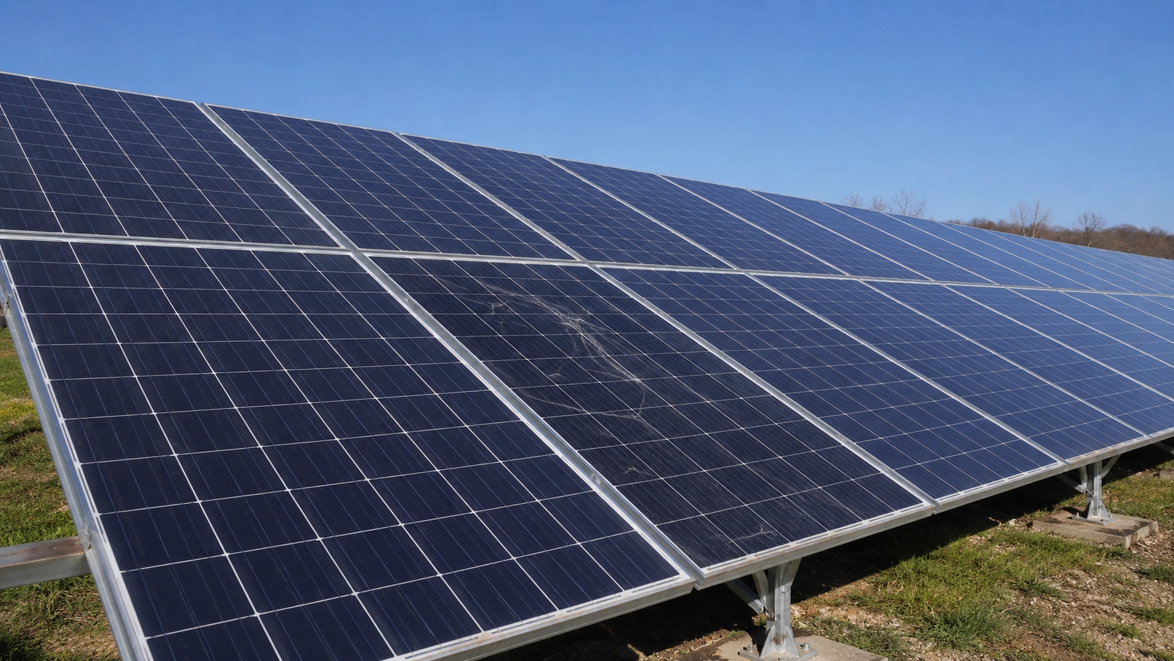
A module may still deliver near-normal power after its glass breaks. A normal current-voltage result does not prove that insulation and mechanical safety are acceptable.
Preserve the Evidence
Before removal, take:
- A full-array photograph
- A full-module photograph
- Close photographs of the suspected origin
- Photographs of all four clamps
- Rear-side photographs
- Rail and support photographs
- Images showing row and module position
- Photographs of nearby undamaged modules
- Packaging photographs when transport damage is suspected
Place a ruler beside close defects so the image shows size. Record measurements in millimetres and identify the tool used.
"The rail looked uneven" is weak evidence. "The front-right support was 4 mm higher than the front-left support" is much more useful.
Do not clean, grind or unframe the suspected origin before examination. If fragments must be collected, separate them by module and original position.
Keep copies of:
- The installation manual used at the time
- Torque-tool calibration records
- Delivery and unloading reports
- Weather records
- Cleaning schedules
- Tracker alarms
- Inverter insulation or arc-fault alarms
- Previous inspection photographs
Safety After Glass Breakage
A cracked module may continue generating DC power. Turning off the inverter does not always remove voltage from the module string.
Broken glass can lead to:
- Moisture entering the laminate
- Cell and ribbon corrosion
- Lower insulation resistance
- Ground faults
- Hot spots
- Internal arcing
- Loose falling fragments
- Exposed live parts
IEC 61730-1 covers module construction requirements intended to reduce electric-shock, fire and mechanical hazards.[11] IEC 61730-2 defines the related safety tests and pass criteria.[12]
Do not:
- Walk on the module
- Push on the cracked area
- Spray water onto it
- Open the junction box
- Disconnect live DC connectors
- Cover the crack with ordinary sealant
- Remove fragments before documentation
Sealant does not restore the original glass strength, insulation system or safety certification.
Immediate action is required when there is:
- Smoke or visible arcing
- Burned laminate
- Exposed conductors
- Repeated insulation alarms
- Water entering the crack
- Loose glass above people or equipment
The module should be isolated and replaced by qualified personnel. See Why Do Solar Modules Delaminate for more detail on moisture entry, layer separation and corrosion after module damage.
How to Prevent Repeat Failures
Check the exact module construction before purchase and installation. Do not rely only on rated power, warranty length or a general certificate.
Review:
- Full model number
- Front and rear glass thickness
- Glass heat treatment
- Module dimensions and weight
- Frame height and wall thickness
- Approved clamp zones
- Clamp length and torque
- Tested mounting orientation
- Rail-spacing limits
- Mechanical-load test arrangement
- Packaging requirements
- Field history for the same construction
Match the module to its real installation environment. The manufacturer provides separate information for commercial and industrial systems and utility-scale systems.
During delivery and installation:
- Inspect every pallet before unloading
- Record visible packaging damage
- Support large modules during lifting
- Keep corners away from hard surfaces
- Measure rail level
- Confirm tracker alignment
- Use the approved clamp type
- Keep clamps within the specified zones
- Use a calibrated torque tool
- Make sure the frame is seated before tightening
- Check front and rear clearances
Connect each serial number with its pallet, row and installation date. These records make later failure mapping much faster.
IEC 62446-2 covers preventive and corrective PV maintenance, worker safety, fire prevention and module cleaning.[13]
Inspect relevant areas after:
- Strong wind
- Heavy or uneven snow
- Tracker faults
- Cleaning incidents
- Foundation movement
- Repeated insulation alarms
Replacing only the broken module may not solve the problem. A new module can crack again on the same uneven rail, under the same incorrect clamp or against the same torque tube.