Why do solar modules delaminate | Moisture Ingress, Thermal Cycling, Encapsulant Aging
Solar module delamination is caused by the combined effects of moisture ingress, thermal cycling, encapsulant aging, UV exposure, mechanical stress, and manufacturing-process variation.
In field operation, delamination is rarely the result of a single isolated factor. Moisture can weaken interfacial adhesion, heat can accelerate polymer degradation, UV exposure can change encapsulant chemistry, and repeated mechanical or thermal stress can enlarge already weakened areas.
Field-failure assessments show that PV module degradation may involve encapsulant discoloration, delamination, corrosion, cracked cells, backsheet damage, junction-box problems, and insulation-related failures. For delamination control, the most important practical approach is to manage the full chain of material selection, lamination quality, edge protection, drainage, installation, and field inspection.
Primary Cause | Typical Starting Point | Main Risk | Key Control Method |
Moisture ingress | Module edges, backsheet defects, frame drainage areas, weakened interfaces | Hydrolysis, corrosion, insulation decline, adhesion loss | Edge sealing, material compatibility, drainage design, insulation testing |
Thermal cycling | Glass/encapsulant interface, cell interconnects, module corners, clamping areas | Interlayer shear stress, solder fatigue, cell cracking, interface debonding | Low-stress module design, proper clamping, controlled lamination, thermal cycling qualification |
Encapsulant aging | EVA layer, backsheet interface, UV-exposed regions, poorly cured areas | Yellowing, acetic acid formation, peel-strength loss, UV and damp-heat degradation | Encapsulant selection, UV protection, crosslinking control, damp-heat testing |
Manufacturing process variation | Lamination, curing, glass edge processing, storage and transport | Incomplete bonding, residual stress, hidden cracks, early delamination | Process-window control, gel-content testing, peel testing, incoming material inspection |
Further reading: IEA PVPS report on PV module field failures.
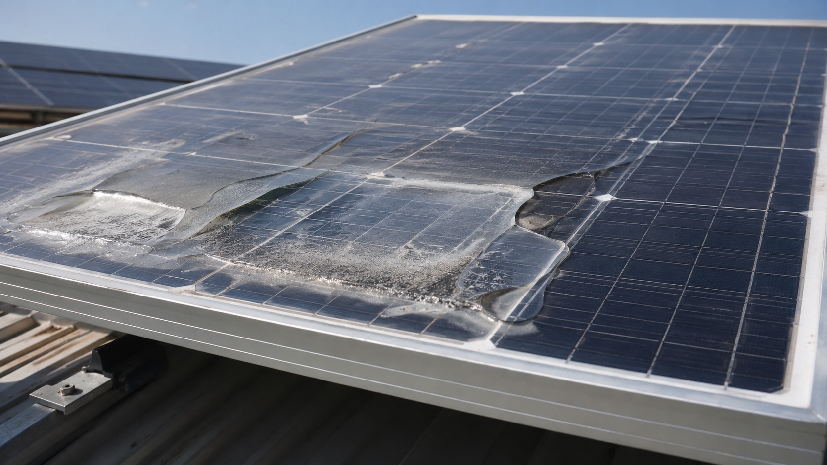
Moisture Ingress
Seal Failure
Seal failure is one of the common routes for moisture to enter a PV module. Edge regions are repeatedly exposed to UV radiation, temperature fluctuation, humidity, mechanical load, and frame-related stress. Over time, these stresses can weaken the sealant and reduce adhesion at the glass, backsheet, or frame interface.
The moisture-blocking performance of an edge seal depends on sealant chemistry, bead geometry, bond-line quality, surface cleanliness, curing state, and compatibility with adjacent materials. A sealant with acceptable bulk properties can still fail early if the glass or backsheet surface is contaminated before bonding.
Moisture exposure is a critical concern because water ingress is correlated with increased corrosion rates in PV modules. NREL encapsulant research also notes that EVA has relatively high moisture diffusivity, meaning that even when an impermeable backsheet is used, moisture entering from the module sides can still diffuse through the module over time.
Seal-Related Parameter | Reliable Control Point | Meaning for Delamination Risk |
Edge-seal adhesion | Verify adhesion to glass, backsheet, and frame materials after aging | Poor adhesion creates interfacial paths for water vapor and liquid water |
Sealant water-vapor resistance | Select materials with suitable WVTR and long-term outdoor stability | Lower moisture permeability reduces long-term water accumulation at laminate edges |
Surface preparation | Control cleaning, drying, and contamination before sealing | Dust, oil, release agents, and process residues can sharply reduce bond strength |
Sealant geometry | Follow the sealant supplier's recommended bead size, curing condition, and process window | Insufficient sealant volume or incomplete curing increases early cracking risk |
Damp-heat reliability | Use damp-heat testing and post-test insulation/visual inspection | Moisture-sensitive interfaces are more likely to show adhesion loss after high-humidity exposure |
Once the seal loses compression or adhesion at the interface, moisture can move from the edge into the laminate. Moisture then accelerates EVA hydrolysis, corrosion of metallization and interconnects, and loss of insulation resistance.
Interface bond quality between sealant, backsheet, and glass is therefore as important as the intrinsic sealant material. Cleaning, drying, curing, and storage conditions should be controlled as part of the module reliability process.
For seal-related delamination, the most important prevention point is not only choosing a low-permeability sealant, but also maintaining a clean, continuous, and well-cured bond line.
· Thermal expansion mismatch and UV aging can create micro-gaps at material interfaces.
· Moisture entering those gaps can accelerate corrosion, EVA degradation, and insulation decline.
· Damp-heat exposure is a practical way to screen moisture-sensitive materials and weak interfaces.
· Field inspection should focus on edge discoloration, sealant cracking, bubbles, corrosion marks, and insulation-resistance abnormalities.
Further reading: NREL module encapsulant diagnostic and moisture-ingress research.
Edge Cracks
Glass edges are structurally sensitive areas of a PV module. Cutting, grinding, handling, transport, framing, and installation can introduce edge chips or microcracks. These defects may remain hidden during shipment but propagate under wind load, snow load, thermal cycling, transport vibration, and clamping stress.
Edge cracks matter because they can weaken mechanical strength and create additional paths for moisture ingress. Once a crack connects the external environment with the laminate edge, moisture can reach the encapsulant and accelerate local delamination.
Edge-Crack Factor | Corrected Technical Description | Practical Meaning |
Initial edge defects | Can include chips, scratches, grinding marks, and microcracks from processing or handling | Small defects can grow under temperature and wind-load cycling |
Edge finishing | Stable cutting, grinding, and chamfering reduce local stress concentration | Better edge quality improves mechanical reliability and moisture protection |
Framing stress | Improper frame assembly or excessive local clamping pressure can intensify crack propagation | Installation quality directly affects long-term edge integrity |
Mechanical load | Wind, snow, transport vibration, and handling shocks can extend latent cracks | Mechanical testing and field inspection should focus on corners and frame contact areas |
Moisture pathway | Cracked edges can connect the external environment with the laminate interface | Moisture ingress becomes easier once edge cracks penetrate the glass or seal region |
Mechanical impact and edge-processing defects should not be described with a universal percentage unless the number comes from a specific factory dataset. In general, the risk is strongly dependent on glass thickness, edge finish, frame design, transport control, and installation method.
Proper edge finishing does not eliminate all glass-related risk, but it reduces stress concentration and lowers the chance that hidden defects will grow into through-cracks.
Glass edge integrity is not only a mechanical-strength issue. It also affects whether moisture can enter the laminate from the module perimeter.
Replacing damaged or poorly processed modules with those using properly finished glass edges, controlled framing, and verified mechanical-load performance can reduce the chance of repeated moisture-related edge failure.
Further reading: IEA PVPS review of PV module failures.
Water Flow Paths
When seal weakness, edge defects, backsheet cracks, or interface debonding exist, moisture can form continuous transport paths inside the module. Water vapor can diffuse through polymeric materials, while liquid water and condensation can move preferentially along weakened interfaces.
Moisture movement should not be described with a fixed universal speed, because it depends on temperature, humidity, module construction, backsheet permeability, encapsulant type, interfacial adhesion, and whether liquid water is present. In tropical or high-humidity climates, moisture-related degradation is typically faster than in dry climates.
Condensation is a critical accelerator because liquid water can maintain prolonged contact with vulnerable interfaces, increasing the risk of hydrolysis, corrosion, and insulation decline.
Water-Path Indicator | Corrected Technical Description | Failure Meaning |
Interface moisture movement | Moisture can migrate along delaminated or weakly bonded EVA/glass and EVA/backsheet interfaces | Progressive moisture movement can enlarge delaminated areas |
Damp-heat exposure | High temperature and high humidity accelerate moisture-related material degradation | Damp-heat testing helps reveal weak interfaces and moisture-sensitive materials |
Insulation resistance | IEC-style evaluation uses insulation-resistance and wet-leakage testing to identify safety risk | Moisture ingress can become an electrical safety issue when insulation performance falls below the required level |
Frame drainage | Drainage design helps reduce standing water and persistent condensate at the module edge | Reducing water accumulation lowers long-term delamination and corrosion risk |
Backsheet integrity | Cracked or hydrolyzed backsheets can increase moisture exposure at the rear side | Backsheet degradation can combine with encapsulant aging and cause insulation problems |
Moisture often accumulates at the lower edge of tilted modules because gravity and drainage conditions influence where condensate remains. This is why frame design, mounting angle, drainage holes, and site cleaning practices all influence long-term moisture-related degradation.
· Closed or poorly drained frame areas can retain water for longer periods.
· Bottom drainage and suitable venting can reduce persistent water accumulation.
· Moisture control requires both good sealing and good drainage.
· Insulation-resistance and wet-leakage testing are necessary when moisture staining, corrosion, or delamination is observed.
Further reading: IEA PVPS photovoltaic failure fact sheets.
Thermal Cycling
Daily Expansion
Solar modules experience repeated field temperature swings during day-night operation. In hot, high-irradiance climates, module surface temperature can reach elevated operating temperatures during the day, while nighttime cooling produces repeated contraction. This daily expansion and contraction generates stress at material interfaces.
The coefficients of thermal expansion for glass, EVA, and aluminum frame differ significantly. Glass has relatively low expansion, aluminum frame expansion is higher, and EVA expansion is much higher than glass. This mismatch generates interlayer shear stress during heating and cooling.
Material | Typical Coefficient of Thermal Expansion | Stress Implication |
Glass | About 8×10â»â¶/°C | Low expansion provides dimensional stability |
EVA | Commonly much higher than glass; often in the 10â»â´/°C order depending on formulation and temperature | High expansion drives interface shear stress |
Aluminum frame | About 23×10â»â¶/°C | Frame expansion can intensify corner and clamping stress |
It is not accurate to describe −40°C to +85°C as a normal daily field swing. That range is an accelerated thermal-cycling condition used in PV module qualification testing. Under IEC 61215 thermal cycling, modules are exposed to repeated high and low temperature extremes to evaluate cells, solder joints, interconnects, encapsulation materials, and interfaces.
In outdoor operation, a module may experience thousands of day-night thermal cycles over its service life. Even when each individual cycle is moderate, repeated cycles can gradually weaken interfacial adhesion and increase the risk of delamination, especially when moisture is also present.
· Thermal expansion mismatch is most severe at module corners, frame contact points, and locally constrained regions.
· Improper clamping can increase local stress and accelerate crack or delamination growth.
· Low-stress encapsulation design and controlled lamination help reduce cumulative interface damage.
· Thermal cycling qualification is necessary, but field reliability still depends on climate, installation, materials, and manufacturing consistency.
Further reading: IEC 61215-2:2021 terrestrial PV module design qualification test procedures.
Stress Accumulation
Repeated temperature changes can cause fatigue in solder joints, ribbons, cells, backsheets, encapsulants, and interfacial bonds. Some stress is relieved during cooling, but residual stress and microscopic damage can accumulate over many cycles.
Thermal-cycling damage should be described as a progressive fatigue process rather than a fixed universal threshold. The number of cycles required for visible delamination depends on module construction, encapsulant type, cell size, interconnect design, glass thickness, backsheet stiffness, lamination quality, moisture exposure, and installation conditions.
Stress Factor | Corrected Technical Description | Reliability Meaning |
Thermal-cycling qualification | IEC 61215 thermal cycling is used to stress materials and interconnects under accelerated temperature extremes | Passing qualification indicates that the design meets a defined test requirement, not that all field degradation is eliminated |
Interfacial adhesion | Repeated shear stress can reduce adhesion, especially after moisture exposure | Lower adhesion increases delamination risk |
Module construction | Glass-glass, glass-backsheet, EVA, POE, EPE, and other constructions show different stress and moisture behavior | Bill of materials strongly affects long-term reliability |
Backsheet stiffness | More compliant rear-side structures can absorb part of the deformation energy | Lower stress concentration can reduce interface fatigue |
Manufacturing quality | Lamination temperature, vacuum, pressure, curing time, and cooling rate affect residual stress | Process deviation can trigger premature interface failure |
Thermal stress becomes more damaging when it is combined with moisture. Moisture weakens interfacial bonds and can change failure modes from cohesive failure within a polymer to adhesive failure at the interface.
Thermal cycling and moisture ingress should be treated as coupled degradation factors, not as independent causes.
· Thermal delamination risk is usually low when materials, lamination, and installation are well controlled.
· Risk increases when thermal cycling acts on already weakened interfaces.
· Large-format modules require careful attention to mechanical constraint and thermal expansion mismatch.
· Adjusting the lamination cooling process can help reduce residual stress.
Further reading: IEC 61215-1-1:2021 crystalline silicon PV module design qualification requirements.
Delamination
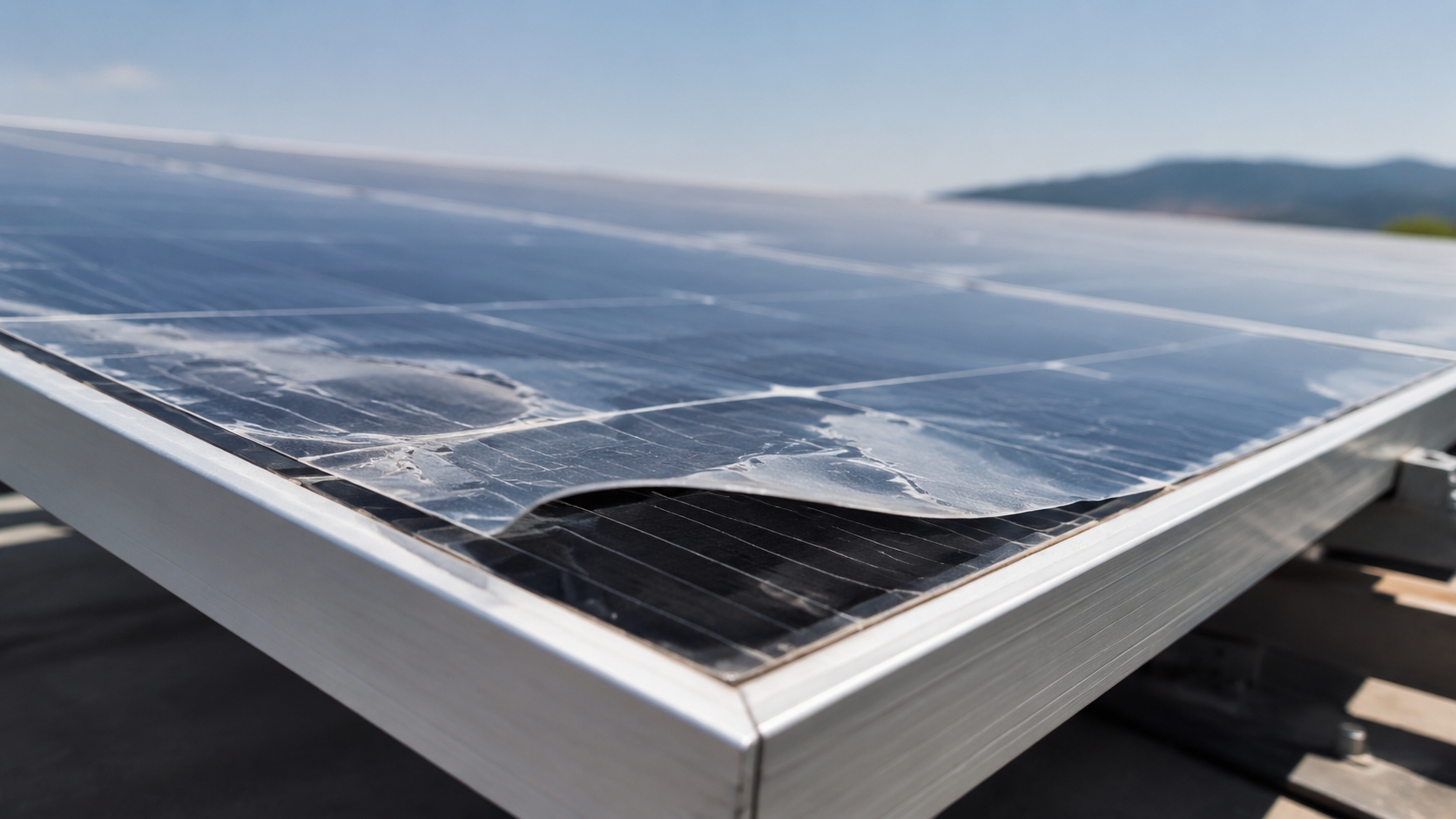
Delamination is the visible result of interfacial adhesion loss. It may occur between glass and encapsulant, cell and encapsulant, encapsulant and backsheet, or inside multilayer backsheet structures. It can be triggered by moisture, heat, UV exposure, poor lamination, mechanical stress, or incompatible materials.
Visible separation gaps, bubbles, milky regions, yellow-brown discoloration, corrosion marks, or local optical haze can indicate delamination or related encapsulant degradation. The first visible location is not always the module center. Delamination can begin at edges, corners, busbar areas, cell cracks, junction-box regions, local hot spots, or mechanically stressed clamping areas.
Delamination Factor | Corrected Technical Description | Meaning |
Bubble-like bulges | Local bubbles can indicate loss of adhesion, gas formation, or encapsulant degradation | Visible sign of local interlayer separation |
Curing temperature deviation | Lower-than-required lamination temperature can lead to insufficient EVA crosslinking | Insufficient crosslinking reduces adhesion and durability |
EVA crosslinking | Many EVA systems require a controlled gel-content window, commonly around 80%–90% depending on formulation and supplier requirements | Too low weakens bonding; excessive curing may increase brittleness or processing risk |
Mounting angle | Low tilt can increase dirt and water retention in some site conditions | Persistent water accumulation can accelerate moisture-related aging |
Delamination area | There is no universal 10 cm² automatic replacement rule for all modules and all locations | Replacement depends on location, growth, insulation resistance, power loss, hotspot risk, and safety risk |
Electrical safety | Delamination near conductors, cells, edges, or the junction-box region requires insulation and wet-leakage evaluation | Electrical risk is more important than visual area alone |
If a delaminated area is close to busbars, cell metallization, edges, or the junction box, the module should be inspected immediately. The decision to monitor, repair, or replace should be based on visual growth, insulation resistance, wet leakage current, power loss, hotspot risk, and warranty requirements.
Yellow or brown residue inside bubbles may be associated with EVA degradation byproducts. EVA can generate acetic acid during degradation, and acetic acid can accelerate corrosion of metallic components inside the module.
· Delamination increases optical reflection and reduces light reaching the cell.
· Debonded areas can leave cells less mechanically supported.
· Moisture trapped inside delaminated areas can accelerate corrosion and insulation decline.
· Curing temperature, curing time, vacuum level, and lamination pressure must follow the encapsulant supplier's process window.
Further reading: Study on EVA lamination conditions, crosslinking, and interfacial quality.
Encapsulant Material Aging
EVA Yellowing
EVA yellowing is a common visible aging feature in PV modules. It should not be attributed simply to a photo-Fries rearrangement of vinyl acetate units. A more accurate explanation is that EVA discoloration is associated with thermal and photothermal degradation, deacetylation, chain scission, crosslinking changes, loss or reaction of additives, and formation of chromophores such as conjugated polyene-related structures.
Yellowing is often accompanied by acetic acid formation and changes in optical transmittance. Severe yellow-browning can reduce the amount of light reaching the cell and may contribute to measurable power loss.
EVA yellowing is not only an appearance problem. When optical transmittance declines significantly, module current and output power can also decline.
Yellowing Indicator | Corrected Technical Description | Meaning |
Initial EVA transmittance | High-quality EVA normally has high visible-light transmittance before aging | High optical transmission is required for efficient light capture |
Severe yellowing | Can produce visible yellow-brown discoloration and lower optical transmission | Optical loss can reduce module current and power |
Acetic acid formation | EVA degradation can produce acetic acid, especially under heat, UV, and moisture exposure | Acetic acid can accelerate corrosion and interfacial degradation |
POE and non-EVA encapsulants | POE does not contain vinyl acetate groups and generally avoids EVA-related acetic acid generation | Material choice can reduce acid-related corrosion risk |
UV stabilizer loss | Loss or consumption of UV absorbers can accelerate discoloration | Stabilizer durability affects long-term optical performance |
POE-encapsulated modules are often used where lower moisture sensitivity, reduced acetic acid risk, and improved PID resistance are required. However, POE also requires appropriate processing control, adhesion design, and material compatibility verification.
· EVA yellowing is difficult to reverse after it has occurred.
· Prevention depends on UV protection, encapsulant formulation, lamination control, and material compatibility.
· Low-VA EVA, UV-cut glass, POE, EPE, and co-extruded encapsulants can be selected according to module design and application environment.
Further reading: NREL/DOE report on EVA encapsulant discoloration and degradation.
Adhesion Strength Degradation
Adhesion strength between encapsulant, glass, cells, and backsheet degrades progressively under moisture, heat, UV exposure, and mechanical stress. Damp heat accelerates moisture penetration and can reduce interfacial adhesion, increasing the probability of delamination.
It is not advisable to state a universal initial peel strength or universal post-aging peel value for all modules. Peel strength depends on encapsulant type, glass treatment, backsheet material, primer system, lamination temperature, curing time, storage conditions, and test method.
Adhesion Indicator | Corrected Technical Description | Meaning |
Initial peel strength | Must be measured according to the manufacturer's test method and material system | Different encapsulant/backsheet/glass systems cannot be compared using one universal value |
Damp-heat aging | High humidity and temperature can reduce adhesion and change failure mode | Adhesion loss increases delamination risk |
Premature aging | Low peel strength within early service years usually indicates material incompatibility, poor curing, or bad storage | Early adhesion loss requires root-cause analysis |
EVA crosslinking | Crosslinking must stay within the supplier's recommended process window | Under-curing weakens adhesion; over-curing can affect flexibility and process stability |
Quality monitoring | Gel content, peel strength, lamination records, and visual inspection should be tracked together | Single-parameter inspection is not enough to judge delamination risk |
Damp-heat studies show that moisture penetration can significantly affect adhesion strength within PV mini-modules. This supports the practical view that moisture ingress and adhesion degradation form a self-reinforcing cycle.
The direct consequence of adhesion degradation is the formation of more moisture ingress pathways.
· Moisture weakens interfacial bonding.
· Weaker bonding allows moisture to move deeper into the laminate.
· Degradation products can further weaken adhesion and accelerate corrosion.
· Lamination temperature, vacuum duration, pressure, and cooling rate strongly influence final bonding quality.
Further reading: Study on interfacial adhesion degradation during damp-heat exposure.
UV Degradation
UV degradation of module encapsulants is driven by the combined effect of UV-A and residual UV-B radiation. UV-B has higher photon energy, but most UV-B is blocked by the cover glass. UV-A has lower photon energy but penetrates more deeply and contributes to long-term photo-aging of encapsulants and backsheets.
IEC 61215 UV preconditioning evaluates UV-sensitive module materials across the 280–400 nm range with a defined UV dose. IEC 61345 also addressed 280–400 nm UV testing for PV modules, but it has been withdrawn and should only be cited as a historical UV test standard rather than as a current framework.
UV damage can cause encapsulant yellowing, backsheet chalking, embrittlement, cracking, and adhesion loss. The best protection strategy is not to rely on one layer only, but to combine UV-cut glass, stable encapsulant formulation, and UV-resistant backsheet materials.
UV-Degradation Factor | Corrected Technical Description | Meaning |
IEC 61215 UV preconditioning | Uses UV exposure in the 280–400 nm range to screen UV-sensitive module materials | Part of module design qualification and type approval testing |
IEC 61345 | Historical UV test standard for PV modules; now withdrawn | Should not be presented as a current standard framework |
UV-A | Lower photon energy but stronger penetration through glass and polymer layers | Important contributor to long-term encapsulant and backsheet aging |
UV-B | Higher photon energy but largely filtered by cover glass | Residual UV-B can still contribute to edge and surface aging |
Backsheet aging | UV exposure can cause chalking, cracking, and mechanical-strength loss | Backsheet degradation increases moisture and insulation risk |
Multilayer UV protection | Use UV-cut glass, UV-stable encapsulants, and durable backsheets together | Layered protection slows optical and mechanical degradation |
1. Use UV-cut glass as the primary front-side barrier.
2. Use encapsulants with suitable UV absorbers and long-term photothermal stability.
3. Select backsheets or rear-side materials with verified UV, damp-heat, and insulation performance.
4. Use IEC 61215 and IEC 61730 test results to evaluate reliability and safety, while treating withdrawn standards only as historical references.
Further reading: IEC 61215 UV preconditioning test description.
Additional standard reference: IEC 61345 withdrawn UV test standard.