Bifacial Monocrystalline Silicon Solar Panels vs. Single-Sided | Which One Suits me Best
Bifacial monocrystalline modules can increase power generation by 5%–25% by utilizing rear-side reflections. Monofacial modules have approximately 10% lower costs and are suitable for close-to-roof installations.
If the site is paved with high-reflectivity materials like white gravel and the installation height exceeds one meter, choose bifacial to maximize returns;
If it is a conventional flat-laid roof with no space for rear-side light, choose monofacial.
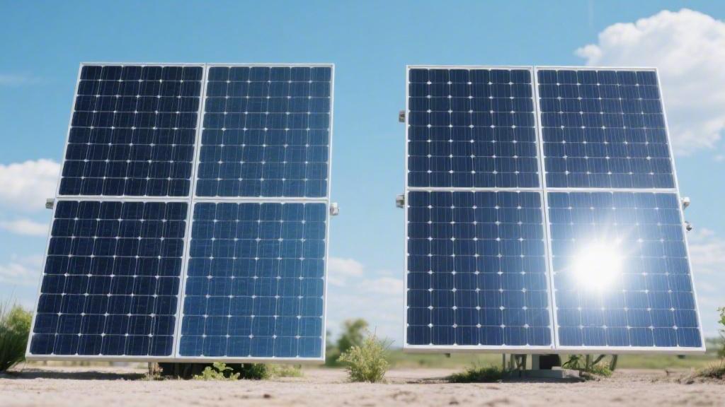
Energy Yield
The front-side power generation efficiency of monofacial monocrystalline silicon modules typically stabilizes between 22% and 24%.
Bifacial modules generate additional electricity when the rear side receives reflected light.
On commercial white-membrane roofs with an albedo of 80%, bifacial modules can increase power generation by 15% to 25%; in common grassland environments with an albedo of 20%, the additional power is approximately 5% to 7%.
Bifacial modules using N-type TOPCon technology have a first-year degradation rate of less than 1%, with subsequent linear annual degradation of only about 0.4%.
Over a 30-year lifecycle, the total power output of a bifacial system is typically 10% to 15% higher than that of a monofacial system of the same specifications.
Albedo & Rear-side Power
Albedo is a dimensionless physical quantity between 0 and 1, representing the ratio of surface-reflected radiation to total received radiation. Under Standard Test Conditions (STC), the front side of a module receives an irradiance of 1,000 W/m².
When installed on a light-colored concrete surface with a reflectivity of 30%, the ground theoretically reflects 300 W/m² of light radiation back upward. The rear side of a bifacial module cannot absorb 100% of the ground-reflected light; it is limited by the module's Bifaciality Factor. The bifaciality factor of N-type TOPCon bifacial modules is usually between 80% and 85%.
The actual effective irradiance received by the rear side is 300 W/m² multiplied by 85%, which is 255 W/m². In specific physical environments, the rear side can provide a physical power gain potential equivalent to 25.5% of the front-side rated power. Different surface materials have vastly different spectral reflection characteristics, leading to order-of-magnitude differences in the energy absorbed by the rear side.
Comparison of common surface cover materials and their measured albedo data in North American and European photovoltaic projects:
Surface Cover Material Physical Type | Measured Albedo | Estimated Effective Rear Irradiation (W/m²) |
TPO (Thermoplastic Polyolefin) Commercial White Roof | 0.75 - 0.85 | 637 - 722 |
Fresh Dry Snow (Scandinavian Peninsula) | 0.80 - 0.95 | 680 - 807 |
Arid Sand/Light-colored Weathered Rock (Arizona) | 0.35 - 0.45 | 297 - 382 |
Aged Light Concrete (Texas) | 0.25 - 0.35 | 212 - 297 |
Temperate Broadleaf Grassland (Europe) | 0.15 - 0.20 | 127 - 170 |
Asphalt Shingles/Dark Gravel Paving | 0.05 - 0.10 | 42 - 85 |
Data from the National Renewable Energy Laboratory (NREL) outdoor test site in Colorado indicates that on TPO white-membrane roofs with an albedo as high as 0.85, bifacial modules can produce a 15% to 20% monthly power gain. When the installation environment changes to common grass with an albedo of only 0.15, the power gain drops rapidly to the 4% to 5% range.
The albedo of a physical surface is not a static value; it degrades over time and with weather conditions. After being exposed to outdoor dust and rain for three years, the albedo of a TPO white-membrane roof usually drops from 0.80 to around 0.65. When calculating the Levelized Cost of Energy (LCOE) for a 25-year lifecycle, engineers set the average albedo of white-membrane roofs at 0.60.
The surface albedo of desert PV plants in Nevada can stabilize at 0.35 during the dry summer season. During the short rainy season, the sandy soil absorbs moisture and darkens, causing the albedo to drop quickly to 0.20. In addition to the physical limitations of the surface material, the amount of reflected light received by the rear side is strictly constrained by the geometric dimensions of the installation space.
The effective light intake on the rear side of the module is non-linearly positively correlated with the clearance height. When the ground clearance is only 0.2 meters, the module's own physical shadow covers more than 80% of the ground directly beneath it. The rear side receives very little reflected light, rendering the albedo useless in low-clearance spaces.
Raising the ground clearance to 0.5 meters allows the shadow area to spread across the ground, and the rear side can capture some light refracted from surrounding unshaded areas. At a height of 0.5 meters, even on a TPO white roof, the rear-side power gain only reaches about 60% of the theoretical maximum.
When the ground clearance reaches the 1 meter to 1.2 meter range, the rear-side radiation reception reaches the inflection point of the physical saturation curve. Increasing the bracket height to 1.5 meters yields an additional rear-side gain of less than 0.5%. Beyond one meter, the cost of the steel for the brackets far exceeds the revenue from the extra electricity generated by the rear side.
Horizontal row pitch also interferes with the effective ratio of ground albedo. Row pitch determines how much ground area between the front and rear rows can be illuminated by sunlight. If the pitch is too narrow, the ground's light-receiving area is severely compressed.
· When the row pitch (the horizontal distance from the top edge of the front row to the bottom edge of the rear row) is 2 meters, the ground illumination area is limited, and the measured average ground-reflected irradiance is below 150 W/m².
· In large-scale ground-mounted power plants in California, the row pitch is widened to 5.5 to 6 meters, allowing the sandy soil between arrays to receive up to 6 hours of unobstructed sunlight, causing the peak ground-reflected irradiance to jump to over 350 W/m².
· If the pitch is expanded to more than 8 meters, although the ground receives more light, the distance to the rear side of the back row is too great, causing the light to scatter in the air; the actual effective radiation increase is less than 1%.
Different geographic latitudes change the geometric angle of solar incidence, which affects albedo utilization. In Oslo, Norway, at latitude 60°N, the solar altitude angle in winter is often lower than 15 degrees. The reflection trajectory of low-angle incident light on snow surfaces is closer to the horizontal line.
When the ground is covered with fresh snow with an albedo as high as 0.90, the rear side of bifacial modules installed at a 45-degree tilt can capture a large amount of horizontal reflected light at a near-perpendicular angle. The snow albedo advantage in Scandinavia is physically amplified under extremely low solar altitude angles.
Field data from Helsinki, Finland, shows that during consecutive clear snowy days in February, the daily rear-side gain ratio of bifacial modules once exceeded 35%. As spring temperatures rise above 0°C, the snow melts and exposes dark soil, causing the albedo to drop rapidly to 0.15 and the rear-side power gain to shrink to 4% within two weeks.
In low-latitude regions near the equator, such as Singapore or Malaysia, sunlight is near-vertical most of the time. Upon reaching the ground, light primarily scatters in all directions as diffuse reflection. Vertically downward light is more easily obstructed by the horizontal shadow of the module itself.
In a TPO roof test project in Singapore, even with an albedo as high as 0.75, the rear-side gain ratio remained at only about 10% due to the self-shading caused by the high solar altitude angle. Colorado, located in the mid-latitudes, had test gain data of 18% for the same roof material, showing an 8% physical data gap caused by latitude differences.
Installation Height & Tilt Angle
Outdoor measurements by NREL in Colorado show that when a module is only 0.15 meters from the ground, its own dark shadow covers 90% of the surface directly below it.
At extremely low installation heights, regardless of how high the surface albedo is, the rear-side power gain is below 1.2%. In low-clearance spaces, the module not only fails to capture surrounding light but also obstructs the natural physical dissipation of bottom heat, causing the silicon wafer's operating temperature to rise abnormally by 2°C.
When the bracket height is raised to 0.6 meters, the physical shadow on the ground begins to recede toward the sides, allowing reflected light from the edge areas to enter the rear glass obliquely. Data from a commercial flat-roof project in Austin, Texas, recorded the specific physical transformation process.
When the height reached 0.6 meters, the average daily effective irradiance received by the rear side of a bifacial system installed on a white TPO membrane exceeded 180 W/m². The actual power gain of the rear side crossed the 8% physical break-even point for the first time in this specific height range.
As the bracket continues to rise to 1.2 meters, the light received by the rear side approaches the peak of the physical parabola, with the gain ratio stabilizing in the data range of 14% to 17%. After the height exceeds 1.5 meters, light scattering loss in the air intensifies, and the absolute power of the rear side increases by only 0.15% per month.
Excessively high bracket columns exponentially increase the procurement budget for Q355 galvanized steel. In the civil design of power plants in Arizona, for every 0.5-meter increase in column height, the construction cost per megawatt rises significantly.
· Increased steel procurement cost for column height: $4,500 to $6,000 per MW.
· Wind load resistance standards: Must pass 130 mph hurricane wind tunnel simulations.
· Size restrictions for large mechanical mowers: A minimum clearance of at least 0.8 meters is required at the bottom.
· Optimal Capital Expenditure (CAPEX) physical height range: 0.8 meters to 1.2 meters.
The optimal tilt for monofacial modules in North America is usually exactly equal to the absolute value of the geographic latitude of the installation site. In Munich, Germany (48°N), monofacial systems are set to a fixed tilt of 48 degrees.
To capture more low-angle ground-reflected radiation, the optimal physical tilt for bifacial modules is usually 2 to 5 degrees steeper than that of monofacial modules. Increasing the tilt of a bifacial system in Munich to 52 degrees results in an absolute irradiance loss of about 0.8% on the front side.
However, the steep 52-degree angle exposes a larger ground area and allows the rear side to align at a better geometric angle with the snow-covered reflective surface. During an 18-day snow period in Munich in January, the rear side at a 52-degree tilt captured a cumulative reflected radiation of over 240 W/m².
The excess output from the rear side in winter compensates for the physical data loss on the front side and creates an additional 6.5% total monthly generation surplus. In extremely low-latitude equatorial regions, sunlight remains at a high-angle vertical state for most of the year.
· Recommended physical tilt for Scandinavian snow zones: 45 to 55 degrees.
· Recommended physical tilt for California mid-latitude desert zones: 25 to 35 degrees.
· Recommended tilt for Singapore equatorial flat-roof installations: 10 to 15 degrees.
Commercial and industrial roof bifacial projects in Singapore typically adopt a 10-degree low-tilt flat-installation scheme. A 10-degree tilt casts the largest physical shadow at noon, covering the gray waterproof coating directly below which has an albedo of 0.70.
The extremely low tilt results in a significant shrinkage of the effective light intake on the rear side, with the average monthly gain ratio stagnating at 4.2%. The primary task of low-tilt design in low-latitude regions is to resist strong monsoon shear; rear-side energy absorption is placed at a secondary level of consideration.
The horizontal bearing main beam (Purlin) on the back of fixed metal brackets is a unique source of optical shading for bifacial modules. Traditional C-steel beams have a physical width between 80 mm and 120 mm, and crossing the back of the module physically shades two rows of silicon cells.
A physical shadow from a 100 mm wide steel crossbeam causes a linear physical attenuation of 2.5% to 3.2% in total rear-side power generation. To eliminate optical shading from bearing beams, structural engineers in Nevada projects introduced specialized short-side clamp fixing technology.
Using short-side clamps at the four corners of the module for mechanical suspension fixing completely clears physical obstacles directly behind the module. The unobstructed dual-glass back structure allows the reflected light utilization at a height of 1.2 meters to climb to a theoretical limit of 98.5%.
In large-scale power plants, bifacial modules are usually bundled with horizontal single-axis (HSAT) tracking systems. The mechanical brackets drive the PV arrays along north-south steel rotation shafts, flipping from east to west at a fixed frequency from dawn to dusk.
At 6:00 AM and 6:00 PM, the front side of the module faces the low-angle sun, while the rear side is fully exposed to the wide opposite sky. Wide-angle sky diffuse radiation becomes the largest physical radiation input source for rear-side gain during these two physical periods.
Large-scale operational data from Andalusia, Spain, shows that in the 1.5 hours after sunrise and before sunset, the bifacial system outputs 15% of the day's rear-side gain. Mechanical tracking brackets also redistribute ground illumination time by adjusting row pitch.
· Physical attenuation of rear-side power caused by traditional beam shading: 2.5% to 3.2%.
· Proportion of gain provided during early morning and late evening edge periods: approximately 15% of the daily total.
· Horizontal single-axis mechanical bracket row pitch setting: 5.5 meters to 7.0 meters.
When the horizontal row pitch is set to 6.5 meters, the mechanical flipping shadow of the front row will not touch the sandy soil at the bottom of the rear array before 4:00 PM. The wide 6.5-meter physical spacing ensures an 8-hour light radiation input channel at the bottom.
When the row pitch is forced to shrink to 4 meters to save on high land lease costs, the absolute ground reflection time is forced to shorten by 2.2 hours. A set of outdoor comparison data from California's Central Valley quantified the data drop brought by the shrinkage of physical spacing: the rear-side gain of a 4-meter pitch plummeted by 38% compared to a 6.5-meter pitch.
Temperature Coefficient & High-Temperature Environments
The rated power of solar panels under Standard Test Conditions (STC) is measured based on an absolute baseline silicon cell operating temperature of 25°C. When the silicon wafer temperature crosses the physical threshold of 25°C, the output power of the photovoltaic module exhibits linear attenuation.
In the direct afternoon sunlight of a Texas summer, the actual physical operating temperature of a dark module surface often soars to 65°C. Compared to the STC 25°C baseline, the 65°C operating temperature creates a massive physical temperature difference of 40°C.
Bifacial modules generally adopt N-type TOPCon or Heterojunction (HJT) silicon wafer processes, and their physical structure has inherent data differences in heat tolerance. In the same 65°C high-temperature environment, the calculated relative power loss for an N-type bifacial module is 11.6%.
Due to the technological grade of the silicon wafer doping process, N-type bifacial modules maintain 2.4% more rated output power during high-temperature daytime periods. The output gap between monofacial and bifacial modules in high-heat environments is further widened by the physical thermal conductivity of the packaging materials.
Bifacial modules use 2.0 mm thick physical tempered glass (Dual-Glass) for rear encapsulation. The physical conduction rate of glass for light and heat radiation is five times that of a plastic backsheet. In the high-irradiance, windless desert environment of Arizona, large amounts of physical waste heat generated by solar radiation accumulate inside the monofacial plastic backsheet.
Bifacial dual-glass modules can conduct the internal energy accumulated by the silicon wafers to the rear air layer at a faster physical rate. Outdoor probe measurements from the University of California show that the absolute physical operating temperature of dual-glass structures is 1.5°C to 2.5°C lower than that of monofacial backsheet modules of the same specifications. Geographic and meteorological data at different latitudes have clear physical intervention results on heat accumulation:
· Mojave Desert, Nevada: Average July temperatures climb above 40°C; monofacial modules recorded a peak daytime physical temperature of 72°C, with thermal loss accounting for 16.4%.
· Bavarian Rooftops, Germany: Peak summer temperature of 30°C; tile roofs lack bottom airflow, and monofacial modules laid flush reach 58°C, with thermal loss fixed at 11.5%.
· Queensland Farms, Australia: Bifacial modules mounted 1.5 meters off the ground benefit from large-scale air circulation at the rear, maintaining a peak operating temperature of 53°C and reducing physical output attenuation to 8%.
Beyond the thermal conductivity of the glass material itself, the conventional installation topology of bifacial modules also provides a ventilation corridor for bottom physical cooling. Bifacial modules are required to have at least a 0.5-meter ground clearance to obtain bottom light, allowing bottom air to flow unhindered through the dual glass on the back.
Monofacial modules are often laid parallel and flush against dark asphalt roofs with a physical clearance of less than 0.1 meters. The narrow, enclosed gap blocks air convection, and the physical greenhouse effect extends the high-temperature working time of monofacial modules by 1.5 hours daily.
An extreme temperature difference of 55°C in HJT bifacial modules causes a 13.2% physical power attenuation. For a monofacial P-type module in the same environment, the same temperature difference would physically consume 19.2% of the generation output. The ground albedo received by the rear side not only transmits visible light energy but different surface reflections also carry absolute physical thermal energy differences.
White TPO reflective roof membranes laid at Colorado warehouse centers not only have a high reflectivity of 0.80 but also reflect 85% of infrared thermal radiation back to the upper atmosphere through material properties. The surface temperature of white membranes under the noon sun is maintained at 35°C. For bifacial modules installed above them, the rear side sucks in relatively cool air at 35°C.
The physical movement frequency of single-axis trackers reshapes the daytime temperature curve of bifacial modules in specific ways. In large-scale plain PV projects in Andalusia, Spain, bifacial modules combined with mechanical shafts adjust the windward angle throughout the day.
During the extremely hot periods from 12:00 PM to 2:00 PM, tracking systems can fine-tune the physical tilt of the modules to a specific angle 5 degrees away from direct sunlight. The absolute light and heat radiation absorption drops by 3% during this period in exchange for a mandatory 2°C cooling of the module surface. Small physical drops in module temperature accumulate into massive absolute power data differences over a 25-year service life.
Lowering the physical operating temperature by 2°C daily not only produces about 0.6% extra power that day but also slows down the physical yellowing and degradation rate of the internal POE film under long-term high-temperature baking. Real-world survey data from North American high-temperature regions after 10 years of operation show that the physical failure rate of backsheet cracking in bifacial dual-glass structures is 8.4% lower than in monofacial modules.
Installation
Monofacial panels are laid flush along the slope of asphalt shingle roofs, requiring a gap between the panel and roof of only 10 to 15 cm.
Bifacial panels need to absorb rear-side reflection (Albedo) and are suitable for installation on surfaces with a reflectivity of 30% or more, such as white TPO flat commercial roofs or light-colored gravel ground.
The bottom clearance height of bifacial panels is recommended to be 1 to 1.5 meters, requiring specialized brackets with no horizontal beams on the back.
Site & Reflectivity
The surface reflectivity of asphalt shingle roofs, widely used in North American independent residences, is only 5% to 7%. Panels are fixed close to the roof surface by standard aluminum rails, with a gap maintained between 10 and 15 cm. The rear side of the module does not participate in the photoelectric reaction, so the reflectivity of the ground environment has no interference with the 18% to 22% front-side efficiency of the monofacial system.
The rear side of bifacial monocrystalline silicon panels is encapsulated with 2.0 mm thick transparent tempered glass, specifically to receive diffuse light (Albedo) reflected from the ground or roof. North American commercial flat-roof buildings widely use white TPO (Thermoplastic Polyolefin) waterproof membranes, which have a surface reflectivity of 70% to 85% in a new construction state. In industrial and commercial projects in California or Texas, high-reflectivity white TPO roofs can provide a 10% to 15% extra power gain for bifacial arrays.
Over time, dust accumulation on the TPO surface causes the reflectivity to drop by 2% to 4% per year. To maintain high albedo indicators, commercial building O&M teams must clean flat roofs over 10,000 square feet with high-pressure water guns every 6 to 12 months.
· New white TPO membrane surface: 75% - 85%
· Aged or dusty white TPO membrane: 50% - 60%
· Light gray weathered concrete base: 25% - 35%
· Black EPDM rubber flat roof: 5% - 8%
Naturally growing grass or dark soil maintains an absolute reflectivity of 15% to 20%. Bifacial modules installed over original ground can only obtain a 3% to 5% extra power output. To boost rear-side light absorption, EPC contractors will lay specialized reflective materials under the solar array.
Laying white gravel is the standard ground modification scheme for large-scale ground PV plants in the US Midwest. Laying 2-inch thick white gravel costs $0.15 to $0.25 per square foot for material and equipment mobilization. White gravel boosts the ground reflectivity from 15% for natural grass to 35%–45%, helping bifacial systems achieve an 8% to 10% rear-side gain. The BOS cost per watt will increase by $0.03 to $0.05.
In desert fringe areas of Arizona or Nevada, when spring weeds reach 30 cm in height, they cast clear physical shadows on the back of the panels. Shadow shading activates the bypass diodes on the back of bifacial modules, causing the output of a single panel to drop by 20% to 33% instantly.
The natural reflectivity of fresh winter snow in northern US states (like Minnesota) is as high as 85% to 95%. Bifacial arrays rely on the strong reflection of snow on the back to continue generating current; the small amount of heat emitted by the cells (3 to 5 degrees Celsius higher than ambient) accelerates the melting and sliding of snow on the front glass.
During periods when monofacial panels are completely covered by 3 inches of snow, instantaneous power generation is zero until ambient temperatures rise and melt the snow. Bifacial systems in the same snow period rely on the back side absorbing up to 300 W/m² of reflected irradiance, maintaining a power output of 15% to 25% of the nominal rating. Bifacial panels are 2 to 4 days ahead of monofacial systems in terms of snow sliding.
To release the physical potential of high-albedo sites, the steel installation height parameters for bifacial panels must be doubled. The minimum edge ground clearance for monofacial ground systems is set at 0.4 to 0.6 meters, merely satisfying flood control. For bifacial modules, to avoid rear-side shadows from the bracket foundation modules, the bottom edge ground clearance must be increased to a range of 1.0 to 1.5 meters.
The increased height forces the metal thickness of the bracket structure to match the wind pressure indices of the American Society of Civil Engineers (ASCE) 7-16 standard. Raising the installation height from 0.5 meters to 1.2 meters requires the cross-sectional area of C-steel columns to expand by 25% to 30% to resist 110 mph gust limits. The increase in material usage makes the procurement budget for a 100 kW bifacial bracket $2,500 to $3,500 higher than for a monofacial bracket.
· Monofacial minimum clearance 0.5 m: Standard wind pressure design, steel usage baseline.
· Bifacial minimum clearance 1.0 m: Rear light shading below 5%, wind pressure standards doubled.
· Bifacial minimum clearance 1.5 m: Excellent diffuse reception height, mandatory thickening of support columns.
· Monofacial conventional row spacing 3.5 m: Prevents front-side winter angle shadow shading.
· Bifacial widened row spacing 5.0 m: Expands the rear ground light area, increasing physical albedo.
The row spacing in the engineering drawings of the two systems differs significantly. The spatial design principle for monofacial arrays is to ensure that from 9:00 AM to 3:00 PM on the Winter Solstice, the front row does not cast physical shadows on the front of the back row. Monofacial row spacing is generally set at 3.5 to 4.0 meters, with a Ground Coverage Ratio (GCR) maintained between 40% and 50%.
Bifacial arrays need to introduce more direct sunlight through the array gaps to illuminate the ground behind, which then reflects back to the panel glass. Structural designers will widen the bifacial row spacing to 5.0 to 6.0 meters, compressing the GCR to 30% to 35%. On the same 1-acre (approx. 4,046 sqm) flat land, a monofacial panel array can install 150 kW to 180 kW of DC nameplate capacity.
Limited by the physical area of expanded row spacing, the absolute installation capacity of a bifacial monocrystalline system in the same area will decrease to 120 kW to 140 kW. In restricted sites with a total area below 0.5 acres, forcibly deploying bifacial systems and compressing row spacing to 3.5 meters will cause the rear of the back-row panels to be physically blocked from receiving diffuse light, causing the gain data to drop to less than 2%.
Specifications & Installation
The physical structure of a monofacial monocrystalline panel consists of a front 3.2 mm thick low-iron tempered glass and a white polymer backsheet. The weight of a standard 60-cell monofacial panel is stable in the range of 18 to 20 kg. Bifacial panels use dual-glass encapsulation technology, with a 2.0 mm thick heat-strengthened glass layer on both sides. At the same physical size, the dual-glass material pushes the total weight of a single bifacial panel to 24 to 28 kg.
The Occupational Safety and Health Administration (OSHA) recommended single-person safe lifting limit is 50 lbs (approx. 22.6 kg). Monofacial panels are within the range where a single installer can independently carry, climb a roof ladder, and align for fixing. The 28 kg limit for bifacial panels mandates that contractors assign two workers for collaborative handling of a single panel during roof or elevated ground work.
In the California PV market, a standard crew of 3 licensed electricians can complete the physical installation of an 8 kW monofacial roof system in 6 to 8 man-hours. For an 8 kW bifacial system of the same capacity, due to handling restrictions, 1 to 2 additional assembly personnel are needed, and the total physical construction time will stretch to 12 to 16 man-hours.
The back of a monofacial panel is non-transparent; installers use UV-resistant cable ties to fasten DC cables to the aluminum crossbeams on the back of the panel. The rear cells of bifacial panels require a very high unobstructed rate. Installers must route the 12 AWG standard DC cables coming from the junction box tightly along the edge of the panel frame.
Edge-routing specifications force the jumper connection distance between single panels in a bifacial system to lengthen by 15 to 20 cm. For a 10 kW ground bifacial array containing 30 panels, edge-routing adds about 5 to 6 meters of PV cable consumption. If junction boxes or main cables form a physical shadow wider than 2 cm on the back of a bifacial panel, the series circuit current of the back cells will instantly drop by 15% to 20%.
Aesthetic Needs
Bifacial modules use a 2.0mm+2.0mm dual-glass structure. The transparent gaps between cells (transmittance of approx. 5%-10%) directly expose roof textures, metal bracket wiring, and micro-inverters, which can look cluttered.
Therefore, for conventional sloped roofs, all-black monofacial models are the first choice;
However, for open structures with BIPV (Building Integrated Photovoltaic) needs, such as carports and gazebos, the glass texture and transparency of bifacial modules better align with modern architectural design.
Residential Pitched Roofs
Over 80% of independent residential roofs in North America and Europe are covered with dark gray or brown asphalt shingles and concrete tiles. In a large dark background, standard-sized (approx. 1722mm x 1,134mm, weight approx. 21 kg) monofacial all-black monocrystalline silicon panels achieve high color matching.
Manufacturers use anodizing to treat the 30mm thick aluminum frame to a matte pure black. The internal wafer cutting and arrangement, combined with a black polymer backsheet, eliminate common silver busbars and white grids.
Under direct sunlight, the entire PV array presents a flat, continuous dark rectangular profile. The roof pitch is usually between 4/12 and 9/12, and the viewing range for pedestrians from the sidewalk is about 15 to 45 degrees. The opaque backsheet of the monofacial panel acts as a physical shield. The underlying aluminum mounting rails (e.g., standard profiles from IronRidge or Unirac), 10 AWG black PV DC cables, and MC4 connectors are all covered in the shadows behind the panels.
A ventilation gap of about 10 to 15 cm is reserved under each panel for cooling by air convection. Most modern residential solar systems are configured with micro-inverters (e.g., Enphase IQ8 series, weighing only 1.1 kg) or power optimizers (e.g., SolarEdge). Hardware is bolted to the side of the rail, usually with a thickness of 3 to 5 cm. The black backsheet of monofacial panels completely blocks light penetration from top to bottom, making complex electrical wiring disappear from natural sight.
Bifacial dual-glass modules laid flush on the same pitched roof present a completely different physical appearance. Panels are encapsulated with 2.0 mm tempered glass on both sides, and the physical gaps between cells provide a light transmittance of about 5% to 10%. Light passing through illuminates the shaded areas under the panel. Light-colored asphalt shingle granules, silver aluminum rails reflecting metal, and L-feet for fixing are clearly visible through the transparent gaps.
Underlying details exposed by dual-glass modules on sloped roof installations:
· Metal reflection from silver aluminum mounting rails.
· Indicator lights and product labels on micro-inverter casings.
· Cable trajectories and connectors fixed with nylon ties.
· Heads of fixing bolts passing through the flashing.
· Accumulated dust and leaves on the roof surface over time.
Leaves, pine needles, and dust around North American suburban homes enter the 15 cm gap under panels via wind and rain. Debris under monofacial panels is completely hidden; as long as it doesn't affect drainage and ventilation, the homeowner cannot detect it from the ground. The transparent areas of bifacial panels make debris accumulation clearly visible.
Dried mud spots (water spots) left on the bottom glass surface after rain look mottled in the sun. Professional cleaning with a low-pressure water gun is required at least twice a year, with a single surface and bottom cleaning costing around $150 to $300.
Comparison data for long-term visual maintenance of monofacial vs. bifacial modules on roofs:
· UV yellowing resistance life of monofacial polymer backsheets reaches 25 years.
· Dust on bifacial glass surfaces causes visual clutter in only three months.
· Increased difficulty in cleaning bottom gaps; high-pressure water can easily damage the waterproofing.
· All-black monofacial modules have a much higher dust tolerance than transparent modules.
To collect photons absorbed on the back, bifacial cells are printed with dense aluminum or silver gridlines. Observed from specific angles, sunlight passes through the glass and produces specular reflection on the rear gridlines, giving the roof a strong industrial grid feel. In contrast, the front of all-black monofacial modules only retains extremely thin black or dark silver busbars.
When installed flush to a roof, bifacial modules have very weak rear-side gain due to the extremely low albedo of asphalt shingles (approx. 5% to 8%). Combined with the narrow 15 cm gap, it is extremely difficult for ambient diffuse light to enter the back of the panel, with actual gain being less than 1.5%. This fails to provide expected power returns while disrupting the architectural consistency of the roof.
To maintain visual consistency, standard hardware selection parameters for monofacial systems include:
· 30mm matte black anodized aluminum frame modules.
· Matching all-black polymer backsheet (zero light transmittance).
· Blackened wind deflectors and end caps.
· Black stainless steel cable clips for tight fixing.
In snowy environments at high latitudes, snow cover further highlights visual differences. After snow slides off all-black monofacial modules, they quickly return to a pure black heat-absorbing surface. If snow under bifacial modules hasn't melted completely, the white background makes the rear junction boxes and messy cables look very prominent through the glass gaps.
In North American communities with strict HOA (Homeowners Association) reviews, the approval rate for all-black monofacial modules is over 98%, while bifacial transparent modules are often rejected due to visible underlying mechanical structures.
Open Structures
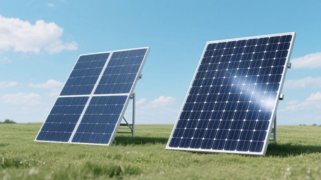
Structures usually consist of steel or glue-laminated wood beams, with roof heights of 2.4–3.2 meters and spans of 4–6 meters. If the roof covering uses bifacial dual-glass solar modules (common size 2,278 mm x 1,134 mm, weight 31–34 kg), the 3–5 mm gaps between cells create a transparency of 6%–10%, allowing natural light to remain in the space below while blocking about 85%–90% of direct solar radiation.
Modules are usually installed on beams at heights above 2.5 meters, staying visible from below. Transparent dual-glass modules expose the rear cells, gridlines, and glass edges, forming a neatly arranged black matrix structure. Low-angle evening light passes through the module gaps, forming regular shadow patterns on the ground. For a 5m x 6m garden gazebo with 12 pieces of 430W modules (total capacity ~5.1 kW), the ground temperature can be reduced by 6–8°C in summer noon.
Visual details in visible structures are determined by material craftsmanship. The tempered glass of bifacial modules is usually 2.0mm+2.0mm or 2.5mm+2.5mm, with black edge seals. In unobstructed spaces, the reflectivity of glass is about 4%, far lower than traditional metal roofing materials. When looking up from below, the cells are arranged in a uniform matrix (cell sizes approx. 182 mm x 91 mm or 210 mm x 105 mm), with consistent array spacing and clear visual order.
Technical details affecting appearance in open structures:
· Module transmittance: 6%–10%, determined by cell spacing.
· Glass thickness: usually 4mm–5mm total thickness.
· Panel weight: 31–34 kg, about 35% heavier than polymer backsheet modules.
· Bracket height: approx. 2.5–3 meters from the ground to ensure walking space.
· Module tilt: 5–12 for drainage and dust prevention.
· Single row span: usually controlled within 3 meters to prevent beam deflection.
Residential-grade solar carports often use galvanized steel or powder-coated aluminum. Black or dark gray frames match the color of dual-glass module frames. A 30 sqm carport can install 10–14 bifacial modules (4.2–6.0 kW). Glass surfaces have high flatness and are less prone to backsheet bubbling or fading in long-term exposure.
When the sun angle is about 60° in the afternoon, light forms light bands about 10–15 cm wide through the module gaps. Compared to opaque metal roofs, light intensity under the gazebo remains at 500–800 lux, similar to being under a tree shade. Traditional opaque modules would reduce light to 100–200 lux, making the space feel noticeably dark.
Visual structures of bifacial modules in carport scenarios are more regular. Common parameters for a two-row module layout are as follows:
Item | Common Parameters |
Carport Dimensions | 5m x 6m |
Number of Modules | 10–12 units |
Single Module Power | 420–450W |
Module Tilt | 7°–10° |
Structure Height | ~3.2 m front, ~2.6 m rear |
Total Capacity | 4.2–5.4kW |
When vehicles are parked under the structure, transparent modules reduce the feeling of oppression. Light passes through the cell gaps, forming neat rectangular shadows on the ground. The cell arrangement of each module is usually a 108 or 132 half-cell structure, with shadow patterns in a repeating matrix.
Installation on open structures requires higher standards for cable management. Since the bottom of bifacial modules is fully visible, cables must be hidden inside profiles or fixed with specialized clips. Standard PV DC cables are about 6–7 mm in diameter, and MC4 connectors are about 55 mm long. If cables hang or cross, they are very noticeable from a 2.5-meter perspective.
Common ways to organize cables:
· Stainless steel cable clips fixed in frame grooves.
· DC cables routed inside aluminum beams.
· Junction boxes oriented uniformly toward the beam interior.
· Micro-inverters installed on the back of the beams.
An installation gap of about 20–25 mm is maintained between modules for thermal expansion and drainage. Arrays use equidistant layouts to ensure glass edges form continuous straight lines. If the span exceeds 6 meters, engineers usually add middle support beams to keep the single span within 2.5–3 meters to reduce glass vibration.
Environmental factors also change the visual performance in open structures. Light concrete ground has a reflectivity of approx. 30%, and gravel can reach 40%. Reflected light enters the module back, making the cells appear a deeper black. Grass has a reflectivity of approx. 20%, resulting in lower visual contrast. When low-angle evening light hits the back, cell edges may show a slight contour light.
After rain, the water film thickness on the glass surface is about 0.2 mm. Hydrophobic coatings on tempered glass allow droplets to slide off quickly. The surface hardness of dual-glass modules reaches Mohs level 6, with higher scratch resistance than polymer backsheets. Over long periods, the transparent structure remains flat; visual changes mainly come from dust and leaf deposits.
In European residential courtyards, a 5 kW-level gazebo PV structure covers about 25–30 sqm, with annual generation of 6,000–7,500 kWh. Glass modules serve as both roofing and power generation. A roof with approx. 8% transmittance keeps the outdoor dining area naturally bright while forming a stable shaded zone during the day.