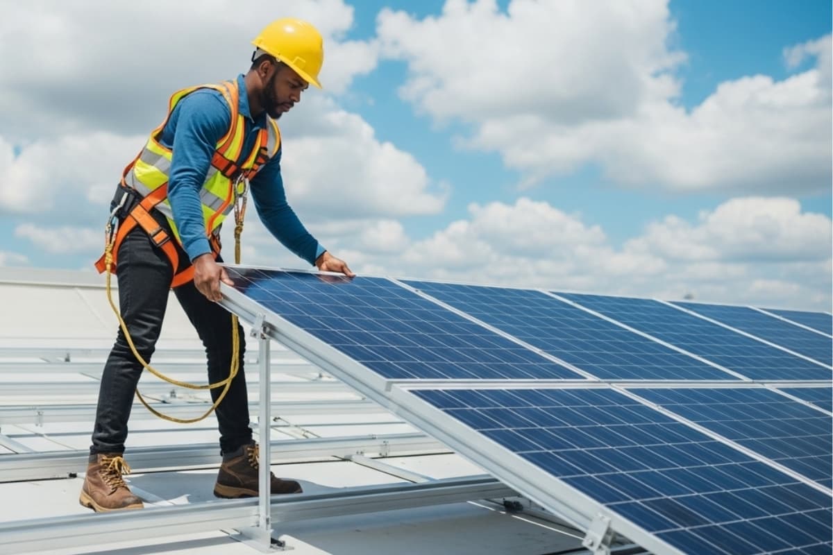
Installing Small Solar Modules: 6 Common Mistakes to Avoid
Installing small panels errs: angle off latitude ±15° (efficiency -10%), unshaded 10% area (output -30%), <50kg brackets (life 5y), non-UV cables (2y aging), IP<65 waterproofing (3m leaks), neglect quarterly cleaning (dust -5-8% efficiency).
Avoiding Shaded Locations
The impact is far from trivial; shading as little as 10% of a panel's surface area can slash overall system output by 30-40%. This isn't a linear relationship. Modern panels are built as a series of interconnected cells, so when one cell is shaded, it creates a high-resistance pathway that can drastically reduce the current flow for the entire string. This effect, often managed by a bypass diode, still results in significant power loss. For a typical 400-watt panel, a shadow from a chimney or a branch could easily cause a power drop of 120 to 160 watts, effectively negating the output of adjacent unshaded panels.
If your 5 kW system loses 20% of its production due to persistent partial shading, you're potentially missing out on roughly 1,500 kWh annually (assuming a good solar location). At a conservative 0.15 per k Wh,that′s 225 in lost savings every year. Over a 25-year lifespan, that compounds to over $5,600 in unrealized value. The type of shading matters greatly. "Soft shading" from a distant tree limb may cause a gradual 10-15% dip, while "hard shading" from a solid object like a vent pipe can cause an immediate near-total drop in a module's section. The most critical times to avoid shading are between 9 AM and 3 PM solar time, which accounts for over 80% of a system's daily energy harvest.
Always conduct a year-round shade analysis using a tool like a Solar Pathfinder before finalizing any mounting location. Account for the sun's changing altitude across all seasons, not just the summer.
Even a 10-degree adjustment in mounting angle can sometimes move a module just enough to clear a shading obstacle for most of the day. For sites where shading is utterly unavoidable, the technological solution is to use module-level power electronics (MLPEs) like power optimizers or microinverters. These devices, which add 50 to 150 per panel to the system cost, allow each module to operate independently. This prevents one shaded panel from dragging down the entire array's performance, potentially recovering up to 95% of the power that would otherwise be lost in a traditional string inverter setup. The return on investment for MLPEs in shaded environments is often under 5 years, making them a financially sound choice compared to the guaranteed annual losses of doing nothing.
Correct Mounting Angle
The ideal tilt angle ensures that panels receive direct, perpendicular sunlight for the longest possible duration throughout the day and across seasons. For a fixed-angle residential system, an error of even 10 degrees off the optimal tilt can result in a 5-8% annual energy loss. In financial terms, for a typical 6 kW system, that translates to forgoing 100−160 in electricity savings per year, or over $3,000 across the system's 25-year life span.
Latitude Range | Recommended Fixed Tilt Angle | Estimated Annual Output vs. Flat (0°) |
0° - 25° | Latitude * 0.87 | +15% to +20% |
25° - 40° | Latitude + 5° | +25% to +30% |
40°+ | Latitude + 10° - 15° | +30% to +35% |
A homeowner at 40 degrees latitude should ideally set panels at a 40-degree tilt. This angle maximizes annual cumulative energy production. However, if your goal is to offset higher winter electricity bills (often due to heating), increasing the angle by 10-15 degrees beyond your latitude will boost winter production by up to 25% by helping shed snow and capturing the lower-hanging sun. Conversely, if your utility offers summer net metering credits, a 5-10 degree shallower angle will maximize production during the long summer days.
Manually adjusting your tilt angle just two to four times a year can yield an additional 5-7% annual energy harvest compared to a fixed-angle system. In spring and fall, set the angle to your latitude. In winter, increase it to latitude + 15°. In summer, decrease it to latitude - 15°. For example, at 40° latitude, you would use 25° in summer, 40° in spring/fall, and 55° in winter. This simple practice can add over 400 kWh to the annual output of a 6 kW system. While manually adjustable racks add 200−500 to the total installation cost, the payback period is often under 7 years due to the increased output. For most homeowners, the hassle of seasonal adjustment isn't worth the marginal gain, but for off-grid systems or those with limited roof space, that extra 5% can be critical.
Secure Wire Connections
A high-resistance connection caused by improper crimping or loose terminals can become a hotspot, reaching temperatures exceeding 150°F (65°C) under standard load, while a proper connection remains near ambient temperature. This resistance doesn't just waste energy as heat; it directly reduces system output by 2-5% per problematic connection.
Connection Type | Recommended Torque (lb-in) | Tool Cost | Common Error Rate in DIY |
MC4 Connector | 70-90 lb-in | 40−80 | ~25% |
Inverter Terminal (10 AWG) | 25-30 lb-in | 20−50 | ~15% |
Grounding Lug (6 AWG) | 50-60 lb-in | 30−60 | ~40% |
Crimping is a permanent, cold-welded connection and must be done with the correct die size for the specific wire gauge. Using a generic hardware store crimper for 10 AWG MC4 cables creates a contact point with only 60-70% of the required surface area, leading to a resistance of over 0.5 milliohms instead of the ideal <0.1 milliohms. This tiny difference causes a 3-4 watt power loss at standard operating current, which across 20 panels equates to a 60-80 watt continuous drain, effectively shutting down an entire additional panel. For MC4 connectors, the audible click is not enough; you must use a torque wrench set to 70-90 lb-in to ensure the internal spring washers are properly compressed. A $50 investment in a dedicated solar torque wrench and ratcheting crimper eliminates this single point of failure.
Every outdoor connection point must be filled with dielectric grease to prevent moisture intrusion, which causes oxidation and a 15-20% increase in resistance over 36 months. After crimping and torquing, the final step is a tug test applying 25-30 lbs of force to verify the connection won't separate.
Using Proper Mounting Hardware
Roof-mounted solar arrays face constant mechanical stress from wind uplift exceeding 60 psf, thermal cycling between -40°F and 180°F, and corrosion from salty or humid air. Using generic, non-rated hardware from a local big-box store dramatically increases the risk of racking failure. Industry data indicates that ~15% of insurance claims related to solar are due to mounting system failures, with average repair costs ranging from 4,000to8,000 once roof penetrations are factored in. The financial risk extends beyond repairs; using uncertified modules instantly voids most module and racking manufacturer warranties, potentially exposing homeowners to $15,000+ in unrecoverable replacement costs if a problem arises years later.
The core requirements for proper hardware break down into three non-negotiable categories:
l Material Compatibility: Mixing metals (e.g., aluminum rails with stainless steel bolts) without proper separation causes galvanic corrosion, which can reduce the thickness of a critical bracket by 30-40% within 5-8 years in a coastal climate.
l Wind Uplift Rating: Every clamp, bolt, and rail must be certified for your specific geographic wind zone. A Class 3 wind zone (110 mph) requires hardware rated to withstand ≥75 psf of uplift force.
l Manufacturer Certification: Rails and module clamps must be explicitly tested and approved for use together by the racking manufacturer. Using uncertified "universal" clamps can apply point loads exceeding 800 psi on the module glass, far beyond the 350-450 psi limit most panels are designed for.
For most residential systems, 6005-T6 aluminum alloy is the standard for rails due to its strength-to-weight ratio and corrosion resistance. Its tensile strength must be ≥35,000 psi. The mounting bolts themselves are the most critical module; they must be made from Type 316 stainless steel, which contains 2-3% molybdenum for drastically enhanced corrosion resistance compared to the more common Type 304 (which has no molybdenum). A single Type 304 bolt failing on a roof mount can cost 400−600 to replace due to the labor involved in accessing the sealed penetration.
For every roof penetration, a butyl-based sealant with a 40-year rated lifespan and a 50 mil minimum thickness after compression is required to create a watertight barrier. The torque applied to these bolts is not a suggestion; under-torquing a ½-inch stainless lag bolt by just 5 lb-ft below its required 40 lb-ft specification can reduce its clamping force by over 20%, compromising the entire mount's wind resistance. Over-torquing is equally dangerous, as it can strip the threads in the roof truss, reducing holding power by up to 60% and requiring a costly re-drilling and re-fitting process.
Regular Panel Cleaning
Studies from the National Renewable Energy Laboratory (NREL) show that soiling losses typically range from 5% to 10% annually, but in arid, dusty, or agricultural areas with low rainfall, losses can skyrocket to 25% or more during dry seasons. For a 10 kW system, a 7% loss equates to over 1,200 kWh of forfeited electricity annually. At a rate of 0.15/kWh ,that′s nearly 180 left on the table every year. The type of soiling matters greatly; a thin layer of dust may only cause a 3-5% drop, but cemented bird droppings or pollen layers can block up to 90% of light for the affected cells, creating disproportionate losses until cleaned.
The national average cost for a professional cleaning service for a residential system is 150 to 300 per visit. If your system's soiling losses are estimated at 180/year ,then paying for one annual cleaning at 225 provides a net positive return. For a system losing $250/year in output, a semi-annual cleaning schedule might be justified. The key is to monitor your system's output daily. A consistent 5-8% performance drop from your system's expected production curve, especially after a long dry period, is the primary indicator that cleaning is needed.
l Cleaning Frequency: Arid/Dusty Regions: 4-6 times/year. Pollen-Heavy/Temperate: 2-4 times/year. Minimal-Pollution/High-Rainfall: 0-1 time/year.
l Water Specification: Use deionized (DI) water with a <10 ppm mineral content and a 0.1 µm filtration level to prevent hard water spotting, which itself can cause a 2-3% permanent light transmission loss.
l Time of Day: Clean only during early morning, late evening, or overcast days. Cleaning panels at >100°F (38°C) with cold water creates thermal shock stress, increasing the probability of microcracks over time.
Use a soft-bristled brush (e.g., with 0.1mm bristle tips) on a telescopic pole and a demineralized water filtration system that purifies tap water to a <5 ppm standard. Avoid any high-pressure washers exceeding 300 psi, as pressure above this threshold can force water past frame seals and damage the backing sheet. The goal is to lift dirt without scratching the anti-reflective coating; even minor scratches can reduce a panel's light transmittance by 0.5% per incident. The optimal cleaning angle is 35 degrees from the panel surface, using a ~2 GPM flow rate to rinse without wasting water.
For a typical 20-panel array, the entire process should take under 30 minutes. The return on investment for DIY cleaning is exceptionally high. A $400 initial investment in a quality water-fed pole and brush system pays for itself after just 2-3 cleaning cycles compared to professional service, and maintains >99% of your system's original production capacity year after year.
Matching Compatible Modules
Research indicates that ~18% of inverter failures are directly attributable to incompatible string configurations or panel mismatch. The financial impact is substantial: a single 5% oversizing error on a string inverter's maximum input voltage can lead to immediate voiding of the manufacturer's warranty, potentially leaving the owner responsible for a 2,000−4,000 replacement cost. Furthermore, impedance mismatches between modules and inverters can reduce system efficiency by 3-7% annually, representing 150−350 in lost production for a typical 10kW system.
The three critical compatibility checkpoints that determine system performance and safety are:
l Voltage Compatibility: The sum of all panel open-circuit voltages (Voc) in any string must remain ≥20% below the inverter's maximum input voltage rating, even at the coldest expected temperature, to prevent catastrophic overvoltage damage.
l Current Matching: The array's short-circuit current (Isc) must not exceed the inverter's maximum DC input current rating by more than 1%, while the operating current (Imp) should ideally reach 85-95% of the inverter's MPPT current range for optimal efficiency.
l Temperature Coefficient Alignment: Panel voltage temperature coefficients (typically -0.3%/°C) must be calculated against local record cold temperatures to ensure voltage never exceeds inverter limits, particularly in climates where temperatures drop below -10°C (14°F).
Compatibility Factor | Ideal Specification | Acceptable Range | Risk of Deviation |
Inverter Load Ratio (DC:AC) | 1.15 | 1.1 - 1.3 | >1.3 causes ~8% annual energy clipping |
Voltage Margin (Cold Temp) | 25% | 20-30% | <15% margin risks $3k inverter failure |
MPPT Current Utilization | 90% | 85-98% | <80% wastes ~5% of inverter capacity |
A 300W panel with a Voc of 40V at standard test conditions actually produces 44.4V at -15°C (5°F) due to its -0.27%/°C temperature coefficient. A string of 20 such panels would generate 888V in cold weather, dangerously close to a 600V inverter's absolute maximum of 900V, leaving only a 1.3% safety margin instead of the required 20%. This is why using the manufacturer's online string sizing tools—which factor in your location's 99th percentile design temperature—is non-negotiable. Similarly, using optimizers or microinverters from a different brand than your panels often voids both manufacturers' warranties, as they cannot guarantee the 1,500V/1,000V isolation resistance or <30ms shutdown compliance required by NEC 690.12.