What Factors Affect the Lifespan of Commercial Solar Panels | Material Quality, Operating Conditions
The effective service life of commercial solar panels—defined as maintaining more than 80% of their initial rated output—is typically 25 to 30 years.
On the materials side, high-quality modules that use dual-glass encapsulation and PID-resistant technology can keep first-year degradation strictly below 1%, with subsequent annual linear degradation as low as 0.35%.
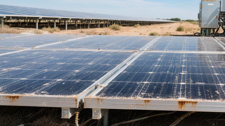
In terms of operating conditions, high temperatures, dust buildup, and extreme weather can significantly affect lifespan.
For example, once panel temperature rises above the standard test condition of 25°C, power generation efficiency typically drops by about 0.3% to 0.5% for every additional 1°C.
Material Quality
Glass Cover
The outermost layer of a commercial PV module is usually a sheet of 3.2 mm low-iron tempered glass, coated with an approximately 100 nm magnesium fluoride anti-reflective film, allowing visible-light transmittance to remain steadily above 93%.
In laboratory hail-impact testing, this type of glass can withstand an ice ball 25 mm in diameter, weighing 7.5 grams, striking vertically at 23 m/s, without developing even the smallest surface crack.
A fully assembled module generally weighs around 22 kg to 28 kg, and the glass alone accounts for about 70% of the total weight. Across repeated expansion and contraction cycles ranging from -40°C to 85°C, manufacturers keep the glass's linear expansion coefficient strictly controlled at 0.000009 meters per degree Celsius.
· The iron impurity content in the glass raw material must remain below 0.015% to prevent light-induced power degradation after 1,000 hours of exposure under strong sunlight.
· The porosity of the surface coating is typically set between 30% and 40%, which helps recover an additional 2% of actual energy yield when the solar incidence angle reaches 60 degrees in the early morning or late afternoon.
Power-Generating Silicon Cells
The mainstream N-type monocrystalline wafers currently on the market are produced in two fixed sizes: 182 mm and 210 mm. Wafer thickness has already been reduced to 130 to 150 microns, while the front-side light-receiving area of each cell exceeds 330 square centimeters.
The rated conversion efficiency of each cell has been pushed from the previous 22.5% to 24% or higher. Once 72 full cells or 144 half-cells are assembled into a module, the maximum output can easily exceed 550 W to 600 W.
The oxygen atom concentration in the silicon material is kept below 10¹⁷ atoms per cubic centimeter. This high-purity standard reduces first-year efficiency loss from the previous 2% to below 1%, helping investors achieve 3% to 5% more total return over a 25-year payback period.
· Using industrial lasers to cut full wafers in half reduces the internal current load by 50%, from roughly 13 A to 6.5 A.
· That halving of current reduces resistive heating losses in the internal metal conductors by 75%, allowing the module's real peak output under high summer temperatures to increase by 10 W to 15 W.
Encapsulation Film
The EVA or POE encapsulation film placed between the glass and the backsheet is generally 0.45 mm to 0.6 mm thick. Factory standards require it to deliver over 90% light transmittance while also maintaining a peel strength above 40 N/cm.
After 1,000 hours in an 85°C / 85% RH accelerated aging chamber, qualified encapsulation film should still maintain a volume resistivity above 10¹⁴ ohm-centimeters, effectively blocking more than 10% leakage loss associated with potential-induced degradation (PID).
The crosslinking ratio during film production must exceed 80%. If it drops below 70%, once cumulative UV exposure reaches 15 kWh/m², the material will begin to yellow significantly, cutting light transmittance by 5%.
· The UV cutoff wavelength of the film is fixed at 360 nm, blocking 99% of the short-wave, high-energy radiation that chemically damages polymer materials.
· Inside the laminator, operating at 120°C, the film's volume shrinkage must be controlled below 2% to prevent invisible microcracks from forming in the 130-micron-thick fragile silicon cells under standard atmospheric lamination pressure.
Operating Conditions
Intense Sun Exposure
Standard test conditions are set at 25°C. For every 1°C rise in ambient temperature, the conversion efficiency of silicon cells drops by about 0.35%.
At summer noon, when ambient temperature reaches 40°C, black glass panels absorb large amounts of radiant heat, and the actual operating temperature inside the module usually rises to 65°C to 70°C.
Using that temperature difference in the calculation, a thermal gap of as much as 45°C can directly reduce the module's rated output by 15.75%.
A brand-new monocrystalline panel rated at 550 W may therefore show an actual output of only around 463 W during the hottest part of the day.
Beyond midday heat stress, desert environments with 40°C day-night temperature swings subject the system to constant thermal expansion and contraction.
Over 10 years of operation, the internal 0.3 mm copper ribbons inside the module must endure at least 3,650 expansion-contraction cycles.
At the junction between the ribbons and the silicon cells, invisible metal fatigue can raise series resistance by 0.5 to 1 ohm.
The additional heating caused by Ohm's law can reduce overall module output by another 2% to 3%, which can translate into nearly 40,000 kWh of lost revenue per year in financial terms.
Wind and Rain
In open plains or coastal areas, strong winds can impose dynamic aerodynamic suction on the aluminum module frame of up to 2400 Pa per square meter.
When instantaneous gust speed reaches 108 km/h, equivalent to Force 11 winds, a panel with an area greater than 2.5 square meters can experience nearly 600 kg of outward lifting force.
The M8 stainless steel bolts securing the frame must provide at least 15 kN of shear strength to prevent the frame from deforming by more than 5 mm within 10 seconds.
Even slight bending of the glass can create hidden internal cracks larger than 50 microns in the 130-micron-thick monocrystalline silicon cells underneath.
Snow load typically reaches the upper design limit of 5400 Pa in static pressure testing.
A 1-meter layer of snow resting on a panel installed at a 15-degree tilt creates a static load of about 300 kg per square meter.
Prolonged overloading can pull the backsheet deformation beyond the dangerous threshold of 1.5 cm, causing local delamination of the EVA layer protecting the cells, with peeling rates exceeding 30%.
Natural Weather Parameter | Type of Physical Stress | Module Tolerance Limit | Efficiency Variation |
Ambient temperature 45°C | Thermal degradation | Operating temperature 85°C | Down 10%–15% |
Day-night temperature swing 40°C | Thermal expansion and contraction cycles | 2,000 mechanical cycles | Internal resistance up 2%–4% |
Gust speed 108 km/h | Dynamic wind load | Negative pressure 2400 Pa | Microcrack probability up 5% |
Snow depth 100 cm | Static snow load | Positive pressure 5400 Pa | Output drops to 0% |
Hail diameter 25 mm | Kinetic impact | Impact speed 23 m/s | Glass breakage risk 1% |
Dust and dirt
In dry industrial zones or arid regions, airborne PM10 particles settle onto the anti-reflective coating at a rate of about 0.5 grams per square meter per day.
If there is no rain for 30 consecutive days, the 15 grams of dust accumulated on the glass can force visible-light transmittance down by 8% to 10%.
For a 5 MW commercial facility, a month-long dry period with no rainfall can cause the inverter's DC input meter to record an energy shortfall of nearly 60,000 kWh.
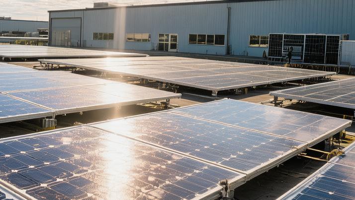
Flat-roof PV arrays installed at tilt angles below 10 degrees cannot rely on light or moderate rainfall below 20 mm per hour to clean the surface naturally, because gravity is not sufficient to wash the panels effectively.
At the junction between the bottom aluminum frame and the glass, a strip of dirt roughly 2 to 3 cm wide can build up and completely block the bottom row of silicon cells.
That dirt band reduces local light transmittance to zero, increasing parasitic resistance in the rerouted current path and causing the output current of a single module to plunge from 13 A to 9 A.