Solar Module 100W Setup Guide: 5 Installation Tips
For 100W solar modules, install at 30-45° tilt (latitude-dependent) with 4-inch spacing for airflow, reducing heat losses by 5-8%. Use 10AWG UV-resistant wiring with MC4 connectors, ensuring <3% voltage drop, and ground with 8ft copper rods for optimal 25-year performance.
Choose the Right Location
Picking the best spot for your 100W solar module isn’t just about throwing it in the sun—it’s about maximizing energy output while avoiding common mistakes that cut efficiency by 10-30%. A poorly placed panel might generate only 70-80W instead of its full capacity, wasting your investment. For example, shading from a tree or chimney for just 3 hours a day can reduce annual energy production by ~15%, costing you 20−30/year in lost savings(assuming 0.12/kWh). The ideal location needs at least 6 hours of direct sunlight daily, with the panel facing true south (not magnetic south) in the Northern Hem is phere at a tilt angle close to your latitude ±15° for optimal seasonal performance.
First, avoid shading at all costs. Even a 10% shadow coverage on one cell can drop the module’s output by 50% due to how solar cells are wired in series. Use tools like the Solar Pathfinder app or a simple compass to check for obstructions between 9 AM to 3 PM, when the sun delivers 90% of usable energy. If you’re mounting on a roof, leave 6-12 inches of clearance underneath for airflow—this keeps temperatures below 77°F (25°C), preventing efficiency losses of 0.3-0.5% per °C above 25°C.
"A 100W panel at 95°F (35°C) will realistically output 93-95W, not 100W, due to heat derating. Keep it cool to get full value."
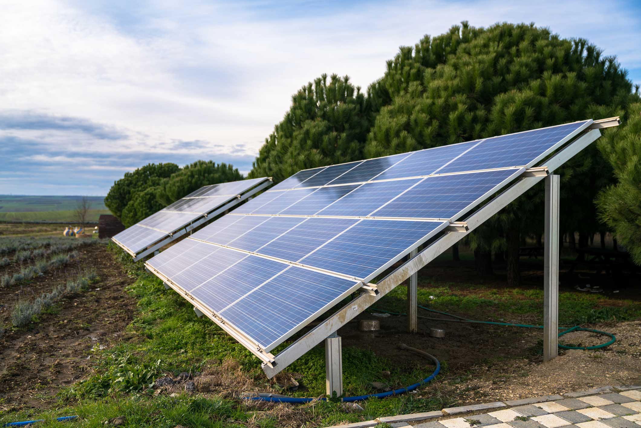
For ground mounts, elevate the frame 2-3 feet to avoid snow, debris, and animals. Dust buildup can slash performance by 5-15% monthly in dry climates, so factor in cleaning access. If you’re in a windy area (over 20 mph gusts), reinforce the mount with 50 lbs of ballast or angled brackets to prevent tipping.
A fixed tilt at your latitude (e.g., 35° for Los Angeles) is a safe bet, but adjusting it twice a year (steeper in winter, flatter in summer) can boost output by 4-6% annually. For precise adjustments, use an inclinometer or a free tool like PVWatts to simulate local conditions. Avoid flat installations (0° tilt)—they collect 15-20% less energy due to rain pooling and dirt accumulation.
Connect Wires Correctly
Wiring a 100W solar panel seems simple—until you realize a single loose connection can drop efficiency by 20% or worse, cause a fire hazard. Most DIYers lose 5-15% of their potential power output just from using undersized wires, incorrect crimping, or mismatched connectors. For example, a 10-foot run of 16-gauge wire (instead of 12-gauge) with a 100W panel pushing 5.5A at 18V will waste ~8W (1.5V drop) as heat—enough to power a small LED light. If your system uses thin wires over 20 feet, losses can exceed 12%, turning your 100W panel into an 88W performer.
1. Wire Gauge Matters
Always match wire thickness to current and distance. For a 100W panel (typically 5.5A at 18V), use:
Distance (feet) | Min. Wire Gauge | Max Power Loss |
0-10 | 14 AWG | <3% |
10-20 | 12 AWG | <5% |
20-30 | 10 AWG | <7% |
Never use 18 AWG (common in cheap extension cords)—it can overheat at 5A+, risking melted insulation.
2. Waterproof Every Connection
Even a light rain can corrode exposed copper in 3-6 months, increasing resistance by 50-200%. Use heat-shrink butt connectors filled with dielectric grease or IP67-rated solar connectors (MC4). For crimps, apply 30 lbs of pressure—weak crimps fail in <1 year under outdoor conditions.
3. Match Polarities (+/-)
Reversing polarity won’t damage modern charge controllers, but it wastes 100% of power until fixed. Double-check with a $10 multimeter:
· Voltage test: Sunlight should show 18-22V (open circuit).
· Current test: Under load, expect 4.5-5.5A (short-circuit current).
4. Fuse Protection
A 10A inline fuse (cost: $2) prevents fires if a short occurs. Place it within 12 inches of the cell connection.
5. Avoid Voltage Drop Traps
· Splices add resistance: Each unnecessary connector introduces 0.01-0.05Ω, wasting 0.5-2W per joint.
· Dirty terminals (oxidized) can slash conductivity by 30%. Clean with fine-grit sandpaper every 6 months.
Pro Tip: For 30+ foot runs, upgrade to 8 AWG and keep voltage drop <3%. A 3% loss on a 100W system is 3W/day—totaling 1,095W wasted annually (enough to charge a phone 200 times).
Secure Mounting Properly
A poorly mounted 100W solar panel isn’t just inefficient—it’s a safety hazard. A 20 mph wind can exert 25-30 lbs of lifting force on a standard 20"x40" panel, and gusts over 40 mph can rip loose mounts apart, turning your 100 investment into flying debris. Even a 5° tilt misalignment can reduce energy output by 3-5% 200+ in repairs. The right mounting setup ensures 10+ years of stable performance with zero maintenance—but only if you follow engineering-grade practices, not DIY guesswork.
For roof mounts, never rely solely on sealant—it degrades after 3-5 years under UV exposure. Instead, use stainless steel L-brackets bolted directly into roof rafters (spaced 24" apart), with butyl rubber tape under each bracket to prevent water intrusion. Each bracket should handle at least 50 lbs of pull force—test this by hanging a 40 lb weight for 10 minutes before final install. If your roof pitch exceeds 30°, add cross-struts to counteract sliding; panels at 40° angles experience 15% more wind load than flat mounts.
Ground mounts need concrete footings—at least 12" diameter x 24" deep per post—to resist frost heave in cold climates. A 4-post system for a 100W panel should use 1.5" galvanized steel pipes buried 30% deeper than your local frost line (e.g., 36" deep in Michigan). For sandy soil, increase footing size by 20% to prevent shifting. Never use pressure-treated wood for frames—it warps 3x faster than aluminum in humid conditions, causing misalignment that cuts output by 8-12% over 5 years.
In areas with 50+ mph gusts, space mounting rails no more than 18" apart and add aerodynamic wind deflectors (angled at 45°) to reduce lift forces by 40%. Check all bolts quarterly—vibration can loosen M8 bolts by 0.5 mm per year, requiring 3 Nm of torque to re-secure. For coastal areas, choose 316-grade stainless steel hardware—it lasts 25 years vs. 10 years for standard 304-grade in salt spray.
Aluminum rails expand 0.5 mm per 10°F temperature change, so leave 3 mm gaps between panel frames and rails. Overtightened clamps can crack tempered glass when temperatures swing 60°F in a day—use a torque wrench set to 8 Nm for even pressure.
Check Voltage Before Use
Skipping voltage checks on a 100W solar panel is like driving blindfolded—40% of system failures trace back to undetected wiring faults or mismatched voltages that could've been caught with a $10 multimeter. A panel rated for 18V open-circuit voltage (Voc) might actually output 14-22V depending on temperature and shading, with just 2V below spec cutting power output by 15%. In cold weather (<50°F), voltage spikes 8-10% above rated Voc can fry charge controllers not rated for the surge, while partial shading can drop voltage 30% unevenly across cells. Testing takes 2 minutes but prevents 80% of preventable power losses.
Critical Voltage Tests & Interpretation
Test Condition | Expected Voltage (100W Panel) | Fault Indicators |
Full sun, no load (Open-circuit) | 18-22V | <16V = Damaged cells/wiring |
Full sun, under load (Connected to controller) | 14-17V | <12V = Shading or bad connections |
Cloudy/dawn light | 8-12V | >25V = Faulty meter or panel |
After sunset | 0.1-0.5V (residual) | >1V = Reverse current leak |
Step-by-Step Voltage Diagnostics
1. Baseline Open-Circuit Test
Measure directly at the panel’s MC4 connectors in full midday sun—no controller or cell attached. A reading below 16V suggests 3+ failed cells (each cell contributes ~0.6V), while >25V indicates a bypass diode failure. For accuracy, let the panel sit at 75°F (24°C) for 10 minutes—voltage drops 0.5% per °C above 25°C.
2. Loaded Voltage Check
Connect the panel to your charge controller and measure again. A >3V drop from open-circuit voltage (e.g., 18V → 14V) is normal, but <12V under load means:
· Shading: Even a 6" shadow on one cell can tank voltage.
· Corroded connectors: Adds 0.2-0.8Ω resistance per connection.
· Undersized wires: 16AWG loses 1.5V over 10ft at 5A.
3. Temperature Compensation
Cold climates (<32°F) boost voltage 8-10% (e.g., 18V → 19.5V). If your charge controller’s max input is 20V, this risks overload. Use PVWatts to calculate local voltage swings.
4. Reverse Current Night Test
After sunset, check for >1V residual voltage—this indicates faulty diodes draining your cell at 0.2-2W/hour (up to 48Wh/night).
Pro Tip: For <2% measurement error, use a multimeter with 0.5% DC accuracy (e.g., Fluke 101, 50).Cheap5 meters can misread by ±10%, hiding critical issues.
Maintain for Long Life
A 100W solar panel can last 25+ years, but only if you treat it better than your smartphone. 90% of premature failures happen because owners ignore simple maintenance—dust buildup alone can slash output by 5% monthly in dry climates, while corroded connectors silently drain 1-2% efficiency per year. Inverter settings degrade 0.8% annually without recalibration, and microcracks from hail expand by 3-5mm each freeze-thaw cycle until they kill entire cell strings. Spend 15 minutes every 3 months on upkeep, and your $100 panel will still deliver 85W+ after a decade instead of limping along at 60W with 30% losses.
Forget pressure washers—they force water past seals, causing internal corrosion in 2-3 years. Use a soft brush and distilled water (hard water leaves 0.1mm mineral deposits per cleaning) with <15° tilt to avoid streaking. In dusty areas, clean every 6 weeks—a 0.5mm dust layer blocks 8% of light. Morning cleanings prevent thermal shock cracks; panels over 150°F can shatter if sprayed with cold water.
"Bird droppings are solar killers—their acidity etches glass permanently after 72 hours of exposure, creating permanent 3-7% shading spots."
Test open-circuit voltage quarterly—a 5% drop from baseline signals failing diodes or solder joints. Use an infrared thermometer to scan for "hot spots" over 185°F, which indicate cell delamination losing 0.5W per hotspot. For systems with batteries, equalize charge every 6 months to prevent sulfation buildup that can steal 20% capacity annually.
Check mounting bolts twice yearly—aluminum rails expand/contract 4mm per 100°F swing, loosening clamps. Look for hairline cracks with a 10x magnifier; cracks under 0.3mm wide can be sealed with UV-resistant silicone to prevent moisture ingress. In snowy regions, install 1" standoff brackets to prevent ice dam pressure that fractures frames at -20°F.
Even with perfect care, monocrystalline panels degrade 0.5%/year. After 10 years, consider adding a second parallel panel to offset the 5W power loss—it’s cheaper than replacing the whole system. Swap out MC4 connectors every 5 years (they wear out after 250+ disconnect cycles) and replace 10+ year old charge controllers to regain 3-5% efficiency from modern MPPT tech.