Can a solar panel have voltage but no current
It is a common phenomenon for solar panels to show "voltage but no current," usually caused by an open circuit.
When the panel is not connected to a load or the cell is fully charged (and the controller has cut off charging), what is measured is the Open-Circuit Voltage (Voc).
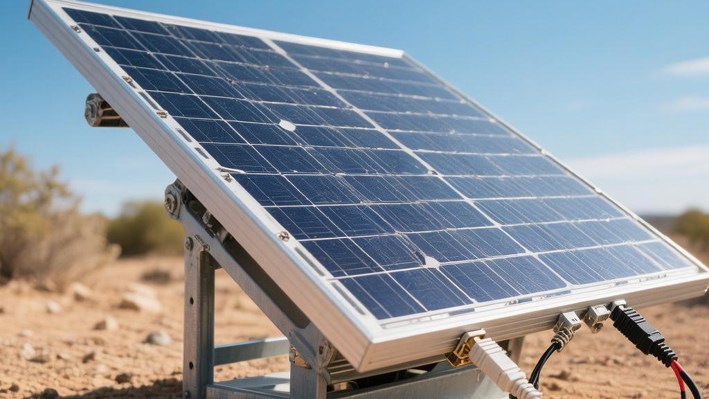
Taking a common 18V panel as an example, even with sufficient sunlight, the ammeter reading will be 0A if it is not connected to a circuit.
Potential vs. Flow
No Load Attached
When you use a multimeter to directly measure the output terminals of the solar panel's positive and negative poles, you are measuring the Open-Circuit Voltage (VOC) of the board.
The internal impedance of a multimeter's DC voltage range is usually set above 10MΩ. For a circuit, this is almost equivalent to the insulating state of air, making it impossible for current to form a closed loop and flow.
· Physical Parameter Analysis: For a typical 550W high-power module, the number of solar cells is usually 144 (half-cell technology). Under standard test conditions, a single cell produces a voltage of about 0.6 V, resulting in a total series voltage of nearly 50 V. However, because no energy-consuming devices such as light bulbs, inverters, or batteries are connected, the electrons in the circuit are in a state of electrostatic equilibrium, and the directed movement of current intensity is 0.
· Energy Conversion Efficiency: In this no-load state, the photoelectric conversion efficiency is 0%. Electron-hole pairs generated by sunlight will recombine inside the module, and the energy cannot be output as electrical energy but is instead converted into thermal energy. According to measured data, the surface temperature of a solar panel under no-load conditions will be 3-5°C higher than that of a panel working with a load, due to heat accumulation from the inability to discharge energy.
Broken Circuit
If your system was originally running normally and the current suddenly drops from 15A to 0A, but the voltage at the panel output remains above 40V, there is a high probability of a physical break in the power transmission link.
Under long-term outdoor UV radiation and humidity changes, the physical properties of connectors will undergo significant degradation.
· Contact Resistance Loss: Dedicated DC cables of 4mm² or 6mm² commonly used in photovoltaic systems have extremely low normal resistance. However, if an MC4 quick connector is not crimped firmly, or if the sealing ring fails and causes the internal copper core to oxidize, the contact resistance may soar from less than 0.5 mΩ to 10 Ω or even higher.
· Fuse Specifications: In a combiner box, DC fuses of 15A to 30A are typically configured. Once a short circuit or current overload occurs at the back end, causing the fuse to blow, the physical structure of the circuit is disconnected. At this point, you can measure a voltage of about 50 V from the panel at the upper port of the fuse, but at the lower port, the ammeter reading will show zero because the circuit is blocked. This voltage difference is a direct basis for troubleshooting the fault point.
Cell is Full
When you are using a 12.8V/100Ah lithium iron phosphate cell pack, its charging logic is strictly controlled by the BMS (Cell Management System).
· Charging Threshold Control: When the single cell voltage reaches 3.65V, meaning the total pack voltage reaches the full-charge critical point of 14.6V, the BMS will send a shutdown command to the charger. At this point, the charging circuit is cut off to prevent the growth of lithium dendrites from causing thermal runaway risks.
· Flow Change Cycle: During the initial Bulk stage of charging, the current may stay at 30A (0.3C charging rate); once it enters the Absorption stage, the voltage stays constant at 14.4V, and the current gradually decreases to about 2A as the cell's internal resistance rises; when 100% SoC is finally reached, the current returns to zero. At this time, the solar panel still has potential energy generated by light, namely voltage, but there is no more storage space to accommodate further charge flow.
Controller Stopped
Temperature Response Mechanism: Internal power modules of high-performance MPPT controllers (such as inductors and capacitors) generate heat during operation. When the temperature of the controller's internal heat sink exceeds 75°C, the system will trigger overheat protection, with a response time usually within 50 ms. At this point, the controller will cut off the output; the panel side shows normal voltage, but the charging current shows 0.
Polarity and Voltage Resistance: If the total voltage of the panels connected to the system exceeds the maximum rated input voltage of the controller (for example, a 100V controller connected to 3 panels of 45V each, totaling 135V), the controller will instantly enter a lockout state to protect internal modules from breakdown. In this fault mode, although the voltage pressure on the panel side is high, the controller refuses to receive it, preventing current from flowing into the system.
Real-World Scenarios
Shaded Areas
When a fallen leaf, bird droppings, or a corner of a building shades even 5% of the cells on a solar panel, that shaded part of the cell changes from a "power source" to a "load."
Under a standard light intensity of 1,000 W/㎡, a normally functioning cell produces about 0.6 V of voltage and about 9 A of current, but the resistance of a shaded cell will rapidly increase due to the lack of photon excitation.
Key Technical Parameter: In the absence of bypass diode protection, if even one cell is completely shaded, the current output of the entire module may drop by more than 90%. At this time, the voltage (VOC) measured by a multimeter might only drop from 45V to 42V; this small fluctuation in voltage masks the truth that the current has almost disappeared.
If the shading persists, the shaded cell will produce a "hot spot effect" because it is forced to pass a tiny current, and the local temperature may rise to over 85°C within 60 seconds.
For a 5 kW residential rooftop system, if one string of modules experiences such local shading, the current of the entire circuit will be limited to an extremely low level by this "bottleneck," resulting in a loss of over 70% in daily power generation revenue.
Loose Wire Ends
Photovoltaic systems are exposed outdoors for long periods, and environmental temperatures can vary by more than 40°C between day and night.
Specifically for MC4 connectors, if the pressure of the crimping pliers was insufficient during installation (the standard crimping pull force should be greater than 310 N), the internal metal contacts will develop tiny gaps over time.
Physical Loss Details: A loose node with a resistance of only 0.1 Ω will generate 10 W of instantaneous heat dissipation at an operating current of 10 A. As the oxide layer thickens, if the contact resistance increases to over 100 Ω, current completely fails to cross this barrier in common 30 V-60 V low-voltage DC systems.
At this point, if you measure at the module end, you will find the voltage reading is very good, perhaps showing 41.2V.
However, because the circuit has formed an effective physical open circuit at the connector, the loop ammeter will be stuck at 0A.
This situation is particularly common in coastal high-salt-mist areas, where the aluminum oxide layer formed after salt mist enters the connector only needs to be a few microns thick to block the directional movement of electrons.
During troubleshooting, if the temperature at the connector is found to be abnormally high (more than 20°C above ambient temperature), even if the voltage is normal, this connector, which takes only 3 minutes to replace but is worth 5 USD, must be changed.
Aging Panels
The design life of solar panels is usually 25 years, but if inferior EVA encapsulation materials or backsheets are used, the modules will suffer from severe PID (Potential Induced Degradation) effects.
Performance Degradation Data: For an aging module that has been in service for 10 years, its open-circuit voltage may still remain at about 95% of the factory value (for example, dropping from 38V to 36V), but its short-circuit current (ISC) may have decayed from the initial 8.5A to 0.2A.
In no-load testing, the feedback from the voltmeter often makes you feel that the "board is not broken yet," but it has lost its ability to drive a load.
This internal loss usually stems from microscopic fractures in the busbars or electrochemical corrosion of the grid lines.
If a 200W panel cannot light up a 50W bulb at noon, and measurement shows the voltage under load collapses from 36V to below 3V instantly, it indicates the internal resistance of the panel is too high to maintain current output.
The temperature is too high
Solar panels are extremely sensitive to temperature, and their output voltage has a negative temperature coefficient characteristic. Usually, the voltage temperature coefficient of monocrystalline silicon modules is about -0.3%/°C.
Temperature Effect Measurement: When the ambient temperature is 40°C, the panel surface temperature may soar to 75°C. Compared to standard test conditions (25°C), the panel's working voltage will drop by about 15%. For some low-voltage off-grid systems, this voltage drop may directly cause the system to shut down.
If the start-up voltage (Vstart) set by your charge controller is 17V, and the panel's maximum power point voltage (VMP) drops to 16.5V due to high temperature, the controller will refuse to close the circuit because it cannot reach the start-up threshold.
On such an extreme summer afternoon, you will see the panel voltage is still 16.5V (dropped but still present), but the charging current is 0A.
At this time, by spraying water for cooling or increasing ventilation gaps, as long as the panel temperature is reduced by 10°C, the current will usually instantly return to normal levels.
The "Invisible" Danger
Arcing is very hot
In DC circuits, especially in systems where the voltage exceeds 80 V, once a disconnected connector (such as a loose MC4 plug) creates a tiny gap due to vibration or wind, the high voltage will instantly break down the air medium to form a DC arc.
DC arcs are different from AC; they have no zero-crossing point, which means once a spark is ignited, it is very difficult to extinguish on its own.
Measured data show that a common 40 V/10 A photovoltaic circuit can produce arc temperatures exceeding 3000°C at the moment of disconnection.
This high temperature can melt aluminum brackets or burn through the TEDLAR insulation layer of the module backsheet in less than one second.
In dry environments, if your system has this "voltage but no current" hidden danger, the breakdown risk further increases when air humidity is below 20% due to static accumulation.
Many rooftop fires are not caused by large current overloads, but by weak arcing due to aging insulation in a no-load high-voltage state; this arcing has a very small initial current, often insufficient to trigger a fuse, but its sustained high temperature is enough to ignite nearby flammable waterproof layers.
Heavy Voltage Drop
When troubleshooting "voltage but no current" faults, the most deceptive data is the magnitude of the voltage drop before and after the load is connected.
This phenomenon stems from the existence of an extremely high-resistance connection point in the circuit, such as a severely rusted terminal screw or a cable with only a few copper strands left inside.
Test State | Ideal Reading (Healthy Panel) | Typical Fault Reading (High Impedance) | Risk Assessment |
Open-Circuit Voltage (VOC) | 41.5V | 40.8V (Seems normal) | Extremely high (False sense of security) |
Voltage after connecting 100W load | 34.2V (Near VMP) | 1.5V (Voltage collapse) | Performance zeroed |
Loop Current (I) | 8.8A | 0.02A | Unable to charge |
Fault Point Heat Generation | < 1W | > 15W (Local high temperature) | Fire hazard |
The most dangerous thing about this high-impedance fault is that when you use a high-internal-resistance digital multimeter for testing, it consumes almost no current, so you can measure a voltage close to the nominal 40 V.
But as soon as you connect a nominal 50W light bulb or DC fan, due to Ohm's Law, most of the voltage will be lost at that high-resistance fault point.
If the resistance at the fault point is 100 Ω, energy will burst at that point in the form of heat when attempting to output current.
This sudden voltage drop phenomenon is the most accurate indicator for judging whether there is hidden physical damage in the system. If the voltage drop ratio exceeds 20%, it indicates that there are lossy modules in the line that must be replaced immediately.
Unchecked Leakage
In large arrays, if the aluminum alloy frame of the module is poorly grounded and the cable insulation has cracks due to UV rays, a weak leakage circuit will form when the morning dew is heavy (humidity exceeding 85%).
Key Detection Data: The ground insulation resistance of a normal system should be greater than 1MΩ. If this value drops below 50 kΩ, the RCMU (Residual Current Monitoring Unit) of the inverter or controller will force the internal relay to shut down within 20 ms for safety reasons.
At this time, when you measure the panel end, the voltage still exists and may even show a fluctuating state, but the charging current will be completely locked at 0A.
This is the result of forced intervention by safety logic. For systems installed for more than five years, this "invisible leakage" can cause frequent system shutdowns after rain.
If you find that the voltage from the panel's positive pole to ground is not zero (for example, measuring 24V to ground in a 48V system), it indicates that the circuit midpoint has failed and a comprehensive insulation performance check must be conducted after shutdown.