After a nearby lightning strike, keep the affected PV circuits isolated and test safety before performance. Start with alarm records, surge protective devices, wiring, bonding, connectors, junction boxes, polarity, string voltage, and insulation resistance. Only after these checks pass should the system be energized for current comparison, I-V curve testing, and infrared inspection. Use electroluminescence imaging when hidden cell or interconnection damage is still suspected.
A module can still show normal open-circuit voltage even when a connector is heat-damaged, a bypass diode has failed, insulation has weakened, or an internal connection has developed high resistance. For this reason, no single reading can confirm that a module or string is safe.
This guide mainly applies to crystalline-silicon modules connected to string inverters. Systems with microinverters, power optimizers, batteries, thin-film modules, bifacial test requirements, frameless modules, or special grounding arrangements may need different isolation and test methods. Always follow the equipment manuals, the project specification, and local electrical rules.
Isolate the Affected Circuit
Do not restart the inverter just to see whether it works. Solar modules produce DC voltage whenever they receive light. Opening the AC breaker stops export to the grid, but it does not remove voltage from the PV strings.
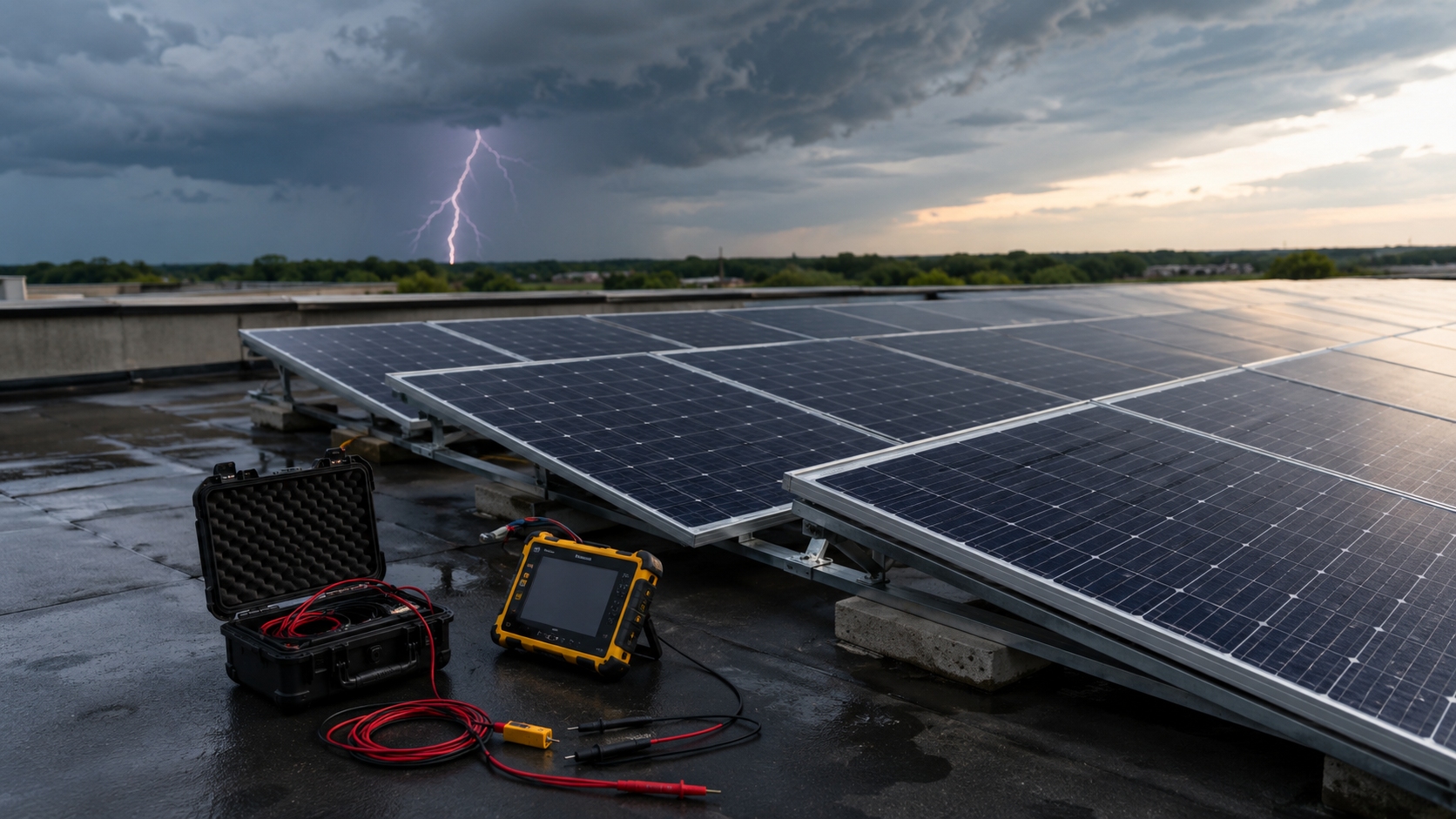
Keep the affected inverter, MPPT input, or string isolated if any of the following is present:
- Smoke, a burned smell, or visible carbonization
- Melted, cracked, loose, or discolored connectors
- A cracked or separated junction box
- Burned, cut, or punctured DC cable
- A failed surge protective device indicator
- An insulation, ground-fault, or arc-fault alarm
- Repeated inverter restarts
- Water inside electrical equipment
- Broken module glass or exposed internal layers
- Arc pits or melted points on frames, rails, clamps, or bonding hardware
PV maintenance and troubleshooting should be carried out by personnel qualified to work on energized DC systems. Residential strings may operate at several hundred volts. Larger systems commonly use maximum system voltages of 1,000 V DC or 1,500 V DC. IEC 62446-2 covers preventive and corrective maintenance for grid-connected PV systems.[1]
| Action | System Owner | Qualified Technician |
|---|---|---|
| Save alarms and monitoring data | Yes | Yes |
| Photograph visible damage from a safe position | Yes | Yes |
| Open an inverter or combiner enclosure | No | Yes, after safe isolation |
| Disconnect DC connectors | No | Yes, after confirming no load current |
| Measure string voltage, current, or insulation resistance | No | Yes |
| Perform I-V, infrared, or EL testing | No | Yes |
Save Evidence Before Repairs
Save the original evidence before clearing alarms, removing an SPD cartridge, cutting off a connector, or replacing a module. This is important for diagnosis, warranty claims, insurance reviews, and later comparison.
Record:
- The estimated time of the lightning event
- The inverter shutdown time and every alarm code
- The affected inverter, MPPT input, string, optimizer, or microinverter
- SPD indicators and remote alarm contacts
- DC voltage, current, and power before and after the event
- Weather, rain, and moisture conditions
- Photographs of all visible damage
- Module, inverter, optimizer, connector, and SPD identification
Download the original inverter event log rather than relying only on screenshots. IEC 61724-1 covers terminology, equipment, and methods used for PV performance monitoring and analysis.[2]
Compare the event with earlier operating periods that had similar irradiance, module temperature, shading, and system status. A sudden change at the time of the storm is more useful than a general comparison with the previous week.
| Observed Change | First Area to Check |
|---|---|
| All inverters report grid voltage or frequency alarms | Grid connection and AC side |
| One MPPT input disappears | Connected string, DC cable, SPD, and inverter input |
| Generation continues but monitoring stops | Gateway, Ethernet, RS485, sensor, and communication surge protection |
| Insulation resistance falls or a ground fault appears | DC cables, connectors, modules, combiner, SPDs, and inverter input |
| One string current drops suddenly | Connector, cable joint, bypass path, shading, module damage, or MPPT fault |
Choose the Test Scope
Not every nearby strike requires every module to undergo EL imaging. The test scope should match the evidence.
| Inspection Level | When It Fits | Typical Work |
|---|---|---|
| Basic | No visible damage, no insulation alarm, SPDs normal, and no clear output change | Data review, visual inspection, SPD check, polarity, string voltage, insulation status, and current comparison |
| Detailed | Failed SPD, missing MPPT, weak string, ground fault, unusual heat, or sudden power loss | Basic checks plus sectional insulation testing, I-V tracing, infrared inspection, and diode diagnosis |
| Module Level | Direct strike evidence, carbonization, internal arcing, several affected strings, unclear fault location, or insurance investigation | Individual module measurements, module-level I-V curves, EL imaging, and engineering review |
A practical test order is:
- Review alarms and monitoring data.
- Inspect the array, wiring, SPDs, inverter, and communication equipment.
- Check bonding and protective continuity.
- Measure polarity and open-circuit voltage.
- Use voltage-to-earth readings only as a fault-locating aid.
- Measure insulation resistance using the approved method and test voltage.
- Compare operating current or perform controlled short-circuit current testing.
- Trace I-V curves when a performance fault remains.
- Energize the tested section under controlled conditions.
- Perform infrared inspection under meaningful load.
- Use EL imaging when hidden cell or interconnection damage is still possible.
IEC 62446-1 describes system documentation, commissioning tests, and inspections used to verify safe installation and correct operation. Original commissioning results are the best baseline after an abnormal event.[3]
Inspect Surge Protection
A nearby strike can damage SPDs even when module glass is intact. Inspect SPDs at DC combiner boxes, inverter DC inputs, inverter AC outputs, distribution panels, monitoring equipment, communication lines, weather stations, and remote sensors.
The power loss may be partial rather than complete. For example, if one string is lost from an inverter input that normally combines 10 similar strings, the available DC contribution from that group may fall by about 10% before temperature, irradiance, clipping, and mismatch are considered. This is only a screening example; the actual system impact depends on the number of strings, MPPT arrangement, and inverter operating point.
Do not assume that the same indicator color means the same condition across all brands. Check the manufacturer's instructions. Also inspect the SPD base, backup fuse, terminals, earth conductor, and remote alarm contact.
Replace an SPD only after confirming:
- Maximum continuous operating voltage
- Maximum PV voltage in the coldest expected condition
- SPD type and circuit arrangement
- Required short-circuit rating and backup protection
- Polarity and earthing arrangement
- Coordination with upstream and downstream SPDs
A new cartridge does not correct a burned base, loose terminal, open fuse, damaged contact, or poor earth connection. Long conductors and large connection loops also increase the voltage developed during a fast surge. IEC 61643-32 gives guidance on selection, installation, and coordination of SPDs for PV systems, while IEC 62305-4 covers surge protection measures against lightning electromagnetic impulse.[4][5]
Trace the Surge Path
Mark every damaged item on the array drawing. The pattern may show whether the event entered through the AC supply, DC wiring, lightning protection system, communication cable, metal roof, or bonding path.
Inspect:
- Lightning conductors, down conductors, test joints, and earth connections
- Module frames, clamps, rails, and bonding points
- Cable trays, metal roofing, and cable crossings
- DC cable routes, combiner boxes, and inverter enclosures
- Communication cables entering the building
Look for small arc pits, bright exposed metal, melted edges, carbon marks, burned washers, damaged cable where it touches metal, and loose or broken lightning protection connections.
Direct current or side flashing often leaves marks near conductive edges, clamps, bonds, and metal joints. An induced surge may damage SPDs, inverter inputs, optimizers, or communication ports without leaving visible marks on a module.
Positive and negative string conductors should normally be routed close together. Separating them increases loop area and can increase induced voltage. Do not add or move bonding conductors without reviewing the original lightning protection design. IEC 62548-1 covers PV array wiring, switching, protection, earthing, and related design requirements.[6]
Inspect Modules and Connectors
Inspect the front glass, rear surface, frame, junction box, output leads, and every accessible connector in the affected circuit. Tongwei's module product page and download center can help identify the correct datasheet, installation manual, and product limits.
On the front side, look for:
- Branching cracks, edge chips, or star-shaped marks
- Melted or pitted points
- Dark internal marks
- Moisture, delamination, or cell discoloration
Use low-angle light to make fine surface damage easier to see. Photograph suspected burn marks before cleaning. Compare unusual marks with the same location on nearby modules so that dirt, old scratches, mineral deposits, or installation marks are not mistaken for lightning damage.
On the rear side, inspect for punctures, burn holes, carbon tracks, blisters, cracks, loose edge seals, moisture, delamination, and discoloration. Carbonization is not cosmetic. Carbonized material can form a conductive leakage path and lower insulation resistance.
Inspect frame corners, clamps, bonding clips, rail contact points, and fasteners. A scratched anodized surface alone does not prove an electrical fault. A melted edge, arc pit, burned bond, loose clamp, or bent frame needs further investigation.
Do not open a sealed junction box unless the manufacturer permits field servicing. A bypass diode or internal connection can fail even when the outside looks normal. Compare junction-box temperature, module voltage, current, and I-V behavior with matched modules.
For connectors, check for:
- Melted or cracked shells
- Loose coupling or broken locking tabs
- Burned cable entries
- Water, corrosion, or carbonized surfaces
- Pulled or damaged cable
- Mismatched connector brands or models
Never unplug a connector while it is carrying current. Replace both halves of a heat-damaged connector pair and inspect the cable beyond the shell. Similar-looking connectors are not automatically compatible because contact dimensions, plating, seals, and locking designs may differ.
Check Bonding and Continuity
Where required by the design, module frames, rails, cable trays, combiner boxes, and inverter enclosures must retain a continuous protective path.
Measure continuity between the points that form the designed bonding route, such as frame to rail, adjacent rail sections, rail to bonding conductor, enclosure to earth, cable tray to earth, lightning protection bonds, and the main earthing terminal.
A continuity buzzer only proves that some path exists. It does not show whether a joint has unusually high resistance. Use an appropriate low-resistance test method and compare the reading with commissioning data, equivalent joints, manufacturer instructions, and local requirements.
Record the exact probe position. A reading on clean metal can differ from a reading taken through paint, oxidation, or anodized coating. Photograph possible arc evidence before disturbing the surface.
Frame bonding and the building lightning protection system are related but separate. A good frame-to-rail result does not prove that every down conductor, test joint, bond, or earth electrode remains intact.
Measure Voltage and Polarity
After safe isolation, measure positive to negative, positive to earth, negative to earth, and polarity. Compare strings only when they have the same module model, module count, orientation, tilt, and similar cell temperature.
Estimate expected open-circuit voltage from the datasheet, string length, and cell temperature. For example, 20 modules with an STC open-circuit voltage of 49.5 V give a simple STC estimate of:
20 × 49.5 V = 990 V
The measured value will normally rise in colder conditions and fall when cells are hot. Crystalline-silicon modules commonly have a Voc temperature coefficient of roughly −0.25% to −0.35% per °C, although the exact value must come from the module datasheet. A 20°C cell-temperature difference can therefore change string Voc by approximately 5% to 7%. Apply the stated coefficient rather than treating 990 V as an exact pass value.
| Voltage Result | Possible Causes |
|---|---|
| Near zero | Open string, disconnected cable, failed connector, open isolator or fuse, wrong test point, or severe short circuit |
| Lower than matched strings | Shorted bypass diode, missing module, bypassed cell section, wrong string length, or internal short circuit |
| Reversed polarity | Incorrect wiring or reversed test leads |
| Normal open-circuit voltage but low power | High-resistance connection, current loss, bypass operation, inverter problem, or cell damage |
Open-circuit voltage is measured with almost no current flowing. A damaged connector or high-resistance joint can therefore show normal voltage but overheat and lose power under load.
Positive-to-earth and negative-to-earth readings can help narrow a ground-fault location on some floating arrays. However, capacitance can create temporary or drifting readings, and the method may not work with every grounding arrangement, inverter topology, optimizer, or connected electronic device. Use these readings to reduce the search area, not to approve insulation.
Test Insulation Resistance
Insulation resistance testing checks for leakage from live DC conductors to module frames, mounting structures, equipment enclosures, or earth.
Low insulation resistance can be caused by:
- Punctured backsheet or damaged rear glass edge
- Damaged cable insulation
- Cracked junction box
- Wet, corroded, or carbonized connector
- Water inside a combiner or inverter input area
- Internal module damage
- Failed SPD or connected electronics
Before applying a test voltage, isolate any equipment that could be damaged. This may include inverters, SPDs, optimizers, microinverters, arc-fault equipment, monitoring devices, and communication electronics.
Do not automatically select the highest insulation-tester setting. The approved voltage and connection method must follow the module, inverter, test-equipment, and project instructions. Some procedures test positive and negative conductors separately to earth. Others connect the live conductors together and test them to earth. One method does not fit every system.
Record the test voltage, connection method, circuit identification, measured resistance, test duration, weather, surface moisture, module temperature, and whether the reading is stable, rising, or falling.
Compare equal amounts of connected equipment. Parallel leakage paths lower the combined reading. For example, two identical 100 MΩ paths in parallel give about 50 MΩ:
1 ÷ Rtotal = 1 ÷ 100 MΩ + 1 ÷ 100 MΩ
Rtotal ≈ 50 MΩ
This is not an acceptance limit. It only shows why a complete inverter input should not be compared directly with one isolated string. On a dry, isolated string, readings may be in the tens or hundreds of megaohms or higher, while a large group of connected strings can show a much lower combined result because the leakage paths are in parallel. Trend, circuit size, weather, and the manufacturer's minimum requirement matter more than one generic number.
A reading that rises slowly may reflect circuit capacitance charging. A reading that remains unstable, falls, or changes sharply after rain may indicate water entry, contamination, or insulation damage. If the fault appears only after rain or morning dew, a dry test may not reproduce it. Do not spray water onto damaged or energized equipment as an informal test.
Divide the array methodically: inverter input, individual string, cable section, connector area, and individual module. This is usually faster and safer than removing random modules.
Compare Current and I-V Curves
Compare current only after the circuit passes the required safety checks. Use strings with the same module count, orientation, tilt, shading, soiling, and similar irradiance. Take readings close together because moving clouds can change current within seconds.
Do not confuse operating current with short-circuit current:
- Operating current is measured while the array is producing power, using reliable inverter data or a suitable DC clamp meter.
- Short-circuit current is measured with an approved PV test procedure and equipment rated to close and open the circuit safely.
Never use a basic multimeter to short a high-voltage PV string.
For example, three matched strings produce 10.1 A, 10.0 A, and 8.8 A under stable conditions. The average of the first two strings is 10.05 A:
Current difference = (10.05 − 8.8) ÷ 10.05 × 100 ≈ 12.4%
A 12.4% difference is large enough to justify further testing, but it is not a universal rejection limit. As a practical screening guide, matched strings measured under stable conditions are often expected to remain within about 5% of one another. A repeatable difference above roughly 10% normally deserves investigation. These percentages are comparison triggers, not automatic pass-or-fail limits. First rule out temporary shade, dirt, cloud movement, sensor error, different orientation, and pre-existing mismatch.
An I-V curve provides more information than one voltage or current reading. Record Voc, Isc, Vmp, Imp, Pmax, fill factor, irradiance, module temperature, and curve shape. IEC 61829 covers on-site I-V measurement of PV arrays, and IEC 60891 covers temperature and irradiance correction of measured curves.[7][8]
| I-V Pattern | Possible Direction |
|---|---|
| Most of the corrected curve is low | Low irradiance, shading, soiling, inactive cell area, or current mismatch |
| Voltage range is shortened | Shorted diode, bypassed section, missing module, or internal short circuit |
| Rounded knee and reduced fill factor | Increased series resistance in a connector, cable joint, fuse holder, junction box, ribbon, or solder joint |
| Steps or notches | Partial shading, conducting bypass diode, mismatch, damaged cell section, or broken interconnection |
Repeat an abnormal sweep and compare it with a matched healthy string. Check the irradiance sensor orientation, temperature sensor contact, changing cloud conditions, temporary leads, and connectors before diagnosing the module.
Research linked to NREL shows that combined light and dark I-V analysis can help distinguish interconnection, junction-box, cable, connector, cell-crack, PID, and optical-loss faults.[9]
Use Infrared Imaging Under Load
Infrared inspection should be performed only after the circuit passes the basic safety checks and is operating under controlled conditions. The circuit must carry enough current for meaningful temperature differences to develop.
Inspect cells, cell groups, junction boxes, bypass-diode positions, connectors, cable joints, fuses, isolators, combiner terminals, and inverter DC inputs.
| Thermal Pattern | Possible Direction |
|---|---|
| One hot cell | Crack, local shunt, dirt, or local shade |
| Hot cell group | Bypass operation, interconnection fault, or mismatch |
| Hot junction-box area | Conducting diode or high-resistance internal connection |
| Hot connector | Loose, corroded, damaged, or poorly crimped contact |
| Whole disconnected module slightly warmer than neighbors | Possible loss of electrical power extraction; confirm circuit state before diagnosing |
Record irradiance, wind, ambient temperature, module temperature, operating current, camera settings, viewing angle, and the temperature difference from a valid reference.
Relative temperature is usually more useful than the hottest color shown by the camera. A connector, fuse holder, or terminal that is consistently about 10°C to 20°C hotter than comparable components carrying similar current should be investigated. A smaller temperature difference can still matter when the load is low, while a large difference caused by reflection or unequal current may not indicate a defect.
Weak irradiance may hide a defect. Strong wind can cool the surface. Fast clouds can create false differences between rows. Automatic camera scaling can also make a small difference look severe. Recheck suspected hot or cold areas from another angle because reflections from the sun, sky, buildings, or inspector can mislead the image.
IEC TS 62446-3 defines outdoor infrared inspection of operating PV modules and plants, including equipment, environmental conditions, procedures, reporting, and personnel requirements.[10]
A melted or carbonized connector should be replaced rather than tightened. Infrared imaging shows temperature differences; it does not prove that insulation is safe.
Use EL Imaging When Needed
Electroluminescence imaging is useful when electrical results show an unexplained problem but the module appears normal. During the test, the module is placed under controlled forward bias and photographed with a near-infrared-sensitive camera.
EL can reveal:
- Cell cracks
- Partially or fully disconnected cell areas
- Broken fingers or busbars
- Failed solder joints
- Inactive cell sections
- Severe shunts
- Uneven electrical response
IEC TS 60904-13 specifies methods for capturing, processing, and interpreting PV module EL images.[11] Tongwei also provides a related overview of EL testing before module installation.
Do not reject a module merely because one thin line appears in an EL image. Check whether the crack separates a cell area, whether that area is electrically inactive, whether power has fallen, whether a hot spot is present, and whether the crack reaches a busbar or cell edge.
EL cannot prove that a crack was caused by the recent lightning event. Compare pre-event images when available and consider transport, installation, hail, walking, wind load, frame stress, and earlier damage.
A thin crack that still retains electrical contact may cause little immediate power loss. A crack becomes more serious when it separates an active cell area, creates a dark inactive region, reduces current, or produces local heating. This is why EL images should be read together with I-V and infrared results rather than judged by crack length alone.
NREL-linked research has shown that EL images taken at different forward-bias levels can quantify partially and fully disconnected areas. Other research shows that electrical contact across a crack can change as module temperature changes, so one image at one temperature may not represent every operating condition.[12][13]
Check Bypass Diodes and Electronics
A shorted bypass diode permanently bypasses one protected cell section. Typical signs are reduced module or string voltage, a shortened I-V curve, lower maximum power, and an unusual junction-box temperature pattern. Current may remain close to normal, so a simple current comparison can miss the fault.
An open bypass diode may not affect output under full, even sunlight. The risk appears when part of the module is shaded and the affected section cannot use its intended bypass path. Do not create deliberate shading on a suspect module unless a qualified technician controls the test.
A heat-damaged diode or internal connection may work when cool and fail after the junction box heats. Compare morning and hot-afternoon behavior when the fault is intermittent.
Do not open a bonded or potted junction box unless the manufacturer allows field repair. Replacing the module is often safer than rebuilding a sealed box on site.
Also check the inverter, optimizers, and microinverters. Compare inverter readings with independent measurements. If independent voltage and current are normal but the inverter reports abnormal values, the MPPT input or sensor may be damaged. If a module passes its electrical tests but an optimizer reports zero output, inspect the optimizer and communication path.
Judge Results Together
Use several matching results rather than one measurement.
| Combined Result | Likely Direction |
|---|---|
| Normal Voc and low corrected Isc | Shading, soiling, inactive cell area, mismatch, or irradiance error |
| Normal Voc and low operating current or Pmax | High resistance, active bypass path, inverter fault, or cell damage |
| Reduced voltage with near-normal current | Shorted diode, bypassed section, or missing module |
| Normal power and low insulation resistance | Safety defect; keep the circuit isolated |
| Hot connector and rounded I-V knee | High-resistance connection |
| Hot cell and inactive EL region | Electrically damaged cell area |
| Fault appears only when wet | Moisture ingress or surface leakage |
| Module passes but device data remains zero | Optimizer, microinverter, communication, or inverter fault |
Evidence that supports a connection with the lightning event includes matching alarm time, several devices failing together, an SPD operating or failing, a sudden change in string data, damage along a possible surge path, and new arc pits, melted metal, or carbonization.
The following do not prove lightning damage by themselves: one low-power module, one crack without a pre-event image, a connector that had already been overheating, a hot spot caused by dirt or shade, mixed connector brands installed earlier, or insulation resistance that had already been declining.
Example: One MPPT disappears after a storm. The string has normal Voc but produces about 12% less current than two matched strings. Its I-V curve has a rounded knee, and infrared inspection shows one hot connector. The first suspected fault is a high-resistance connector or cable joint. EL imaging is not the first test unless the electrical fault remains after the connection is corrected.
Decide Whether to Repair or Replace
Remove a module from service when it has exposed live parts, unsafe broken glass, a punctured or carbonized backsheet, burned output leads, a melted connector, a cracked or wet junction box, insulation below the applicable requirement, internal arcing, a persistent severe hot spot, or unrepairable cable or bonding damage.
Do not use one universal power-loss percentage as the replacement rule. Field power changes with irradiance, cell temperature, soiling, spectrum, shading, module tolerance, and measurement uncertainty.
A small EL crack without an inactive area, hot spot, insulation problem, or measurable power effect does not automatically require replacement. A module with acceptable power but failed insulation must not remain in service. A lower-power module with safe insulation may be a performance or warranty issue rather than an immediate electrical hazard.
IEC 61730-2 lists module safety qualification tests intended to detect failures that may lead to fire, electric shock, or injury. It is a product qualification standard, not a complete field acceptance procedure after lightning.[14]
Do not patch a backsheet, rebuild a sealed junction box, or replace an internal diode unless the manufacturer provides an approved field repair method. An unapproved repair may reduce insulation, sealing, mechanical strength, and warranty coverage.
Restart in Controlled Sections
After repairs, reconnect the affected system one controlled section at a time. On a small commercial array, a basic inspection may take several hours. Detailed sectional testing with I-V tracing and infrared inspection may require a full working day or longer, while module-level EL work can extend the investigation further. The time depends on system size, access, documentation quality, and the number of abnormal circuits.
- Confirm that damaged parts have been removed or correctly repaired.
- Check repaired connector pairs and cable terminations.
- Confirm polarity.
- Confirm acceptable insulation resistance.
- Confirm bonding continuity.
- Reconnect one string or input at a time.
- Watch DC voltage, current, power, and insulation readings.
- Check for returning alarms.
- Perform infrared inspection under operating load.
- Compare output with matched strings.
Stop and isolate the circuit if an insulation, ground-fault, or arc-fault alarm returns, current becomes unstable, a connector heats quickly, or an electrical smell appears.
Continue closer monitoring through a high-output period and normal environmental exposure, especially after rain, morning dew, hot afternoon operation, or strong wind. Do not create a wet condition as an informal test.
Record the Final Findings
The final report should include:
- Array layout and affected circuit
- String and MPPT identification
- Module and equipment serial numbers
- Test instruments and calibration status
- Test settings and connection methods
- Weather, irradiance, wind, and temperature
- Bonding, voltage, insulation, current, and I-V results
- Infrared and EL images
- Removed or replaced parts
- Controlled energization results
- Remaining defects and follow-up actions
Every measurement should identify what was tested, where it was tested, the instrument used, the setting, the result, and the reason it passed or failed.
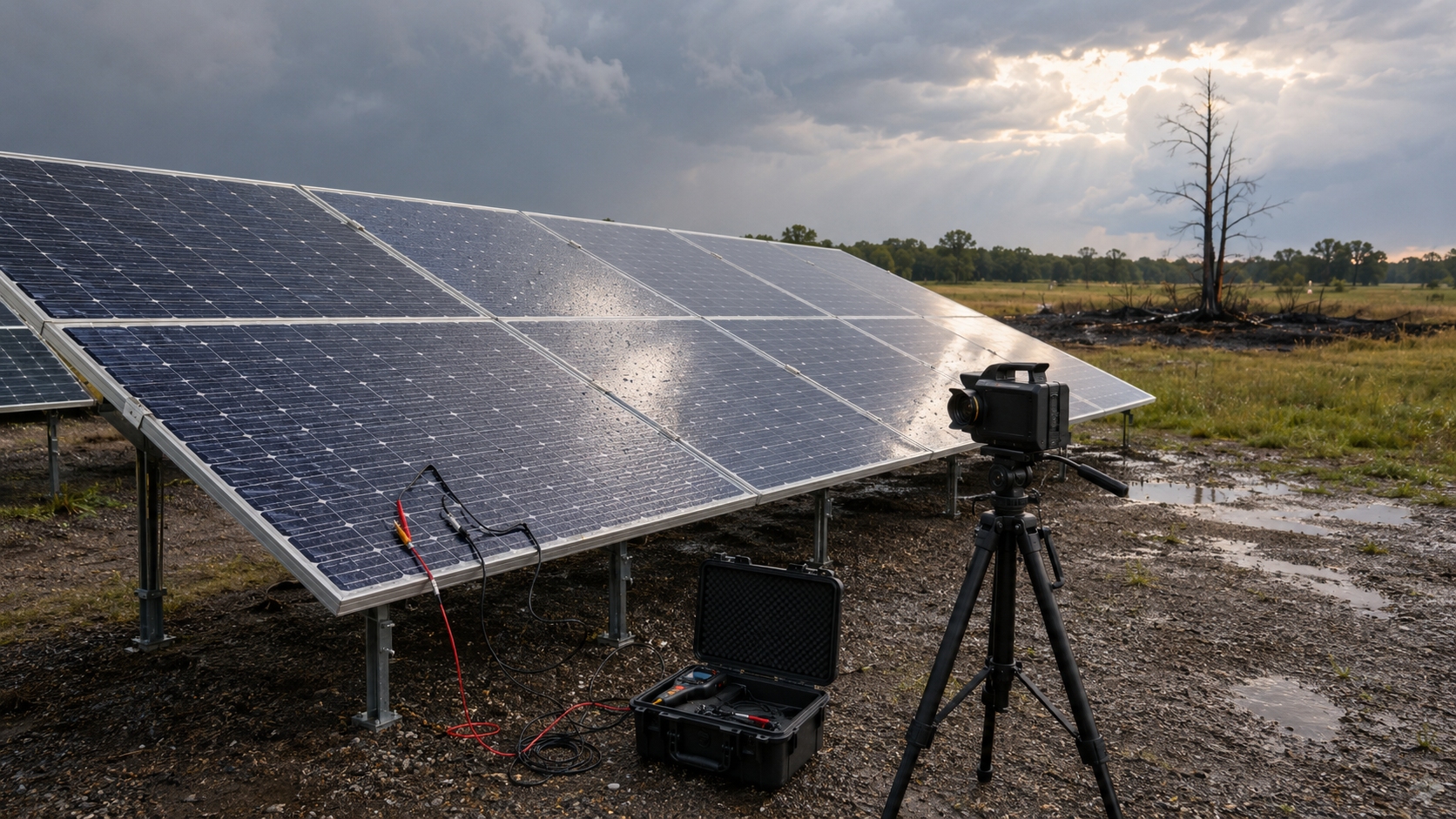
Keep failed SPDs, fuses, connectors, optimizers, and other removed parts when an insurance, warranty, or engineering review may follow. Photograph each item before removal and record its original position.
Separate observations from conclusions. "The connector shell was melted and measured hotter than adjacent connectors" is an observation. "The evidence is consistent with a high-resistance connection or surge-related arcing" is an interpretation.
The IEA PVPS Photovoltaic Failure Fact Sheets provide field-oriented information on common PV failure modes, risks, and possible interventions.[15]