PV connectors usually crack after several years because the plastic housing becomes less flexible while sunlight, temperature changes, cable strain, assembly stress, moisture, or internal heat continues to act on it. The crack often starts around the cable gland, thread, locking tab, molded joint, or another area carrying more force than the rest of the housing.
Water is usually not the first cause. It often enters after a seal or housing has already been damaged, then corrodes the contacts, lowers insulation resistance, and increases electrical heating. A cracked connector should be inspected and replaced, not wrapped with tape or filled with sealant.
IEC 62852 covers PV DC connectors rated up to 1,500 V DC and 125 A per contact. These connectors do not have breaking capacity, so they must not be used to interrupt operating current.[1]
Why the Crack Appears Years Later
Most delayed connector failures need three conditions:
- The housing loses some of its original flexibility.
- One part of the connector remains under mechanical or thermal stress.
- Daily heating, cooling, bending, or vibration slowly enlarges a small defect.
The problem may begin on the day of installation but remain hidden. A rear gland may be too tight, a cable may be pulling sideways, or a metal contact may not be fully inserted. New plastic can often tolerate this stress. After years of outdoor exposure, the same housing may no longer bend without cracking.
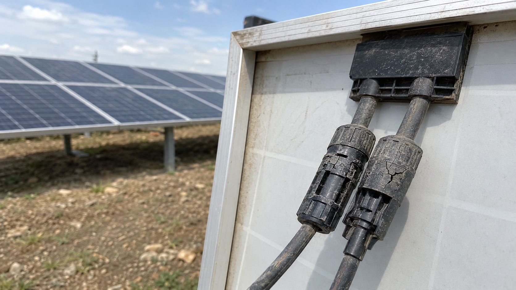
A typical failure develops in this order:
- A small material, assembly, or installation weakness exists.
- Sunlight, temperature changes, and mechanical load reduce the remaining strength.
- A fine crack forms at the weakest point.
- The crack affects the seal, lock, insulation, or contact position.
- Water, dirt, corrosion, or movement makes the damage worse.
- The connector overheats, trips the inverter, develops an insulation fault, or fails completely.
There is no fixed year when connectors should start cracking. The timing depends on the connector material, production quality, climate, operating current, cable routing, assembly method, and maintenance history.
Housing Aging
The outer housing is normally made from an engineered polymer. It must insulate live parts, hold the metal contacts in position, compress the seals, and keep the locking system secure.
Its long-term strength depends on:
- Polymer type and formulation
- UV stabilizers, pigments, and fillers
- Housing wall thickness
- Sharp corners and molded joints
- Production temperature and pressure
- Material and batch control
- Operating temperature
- Mechanical load
The housing does not need to be completely degraded before it fails. A moderate loss of flexibility can turn a scratch, tool mark, thin wall, sharp corner, or molded joint into a crack starting point.
Polymers can also change shape or lose clamping force over time. Under a constant load, the housing may slowly deform. A seal or locking feature held in one position may also lose part of its original force. These time-dependent behaviors are commonly described as creep and stress relaxation.[2]
A connector can still look black and clean after its mechanical strength has fallen. Color alone cannot show whether the housing remains safe.
UV Exposure
Ultraviolet radiation can slowly change the surface and mechanical properties of connector plastics. Outdoor materials contain UV stabilizers, but their performance still depends on the material formula, sunlight level, temperature, and exposure time.
Possible signs of UV aging include:
- A dull or chalky surface
- Fading or uneven color
- White stress marks
- Fine surface lines
- Small cracks around thin sections
- Broken locking tabs after light handling
Fine surface lines may indicate UV aging or chemical stress, but they can also be scratches or molding marks. Compare the affected connector with an unused sample or a shaded connector of the same model before deciding on the cause.
UV damage is more likely when:
- The sun-facing surface is worse than the shaded side.
- Connectors outside the module shade fail first.
- Damage covers a broad surface instead of one loaded point.
- Connectors near reflective roofs, sand, or snow are more affected.
- Failures are concentrated at high-altitude sites.
UV exposure is less likely to be the only cause when the crack is limited to a gland thread, locking tab, cable-tie position, or heat-damaged area.
Temperature Cycling
A connector heats during the day and cools at night. Passing clouds, wind, and seasonal changes add more temperature cycles.
The connector contains plastic, copper alloy, contact springs, cable insulation, conductor strands, and rubber seals. These materials do not expand and contract at exactly the same rate.
Repeated movement can concentrate stress around:
- Cable glands
- Threads
- Locking tabs
- Contact supports
- Thin walls
- Sharp corners
- Molded joining lines
If one main heating and cooling cycle occurs each day, a connector may experience about 365 major cycles per year. Smaller changes caused by clouds and wind can add many more.
| Outdoor service period | Approximate daily thermal cycles |
|---|---|
| 1 year | 365 cycles |
| 5 years | 1,825 cycles |
| 10 years | 3,650 cycles |
| 20 years | 7,300 cycles |
These figures are simple estimates, not connector qualification limits. Actual systems may experience more temperature changes because of passing clouds, shading, wind, and changing electrical load.
The effect is worse when the cable already enters the connector at an angle. As the cable heats and cools, it repeatedly pushes and pulls on the rear housing. Thousands of small movements can enlarge a defect even when no single movement is strong enough to break the connector.
Normal outdoor temperature cycling is different from abnormal electrical heating. Normal cycling affects most of the connector. Electrical heating is concentrated near a poor crimp, damaged contact, incomplete connection, or incompatible connector pair.
Low temperature also matters. An aged housing may be less flexible in cold weather and may crack during movement or maintenance that would not damage it in warmer conditions.
Internal Overheating
Some housings crack because the electrical contact inside the connector becomes too hot.
Every connection has a small amount of resistance. Poor crimping, corrosion, low contact pressure, incomplete mating, or the wrong connector pair can increase that resistance.
Power loss = current² × resistance
The following example shows how a rise in contact resistance changes heat output at 12 A:
| Contact resistance | Heat produced at 12 A |
|---|---|
| 0.5 mΩ | 0.07 W |
| 5 mΩ | 0.72 W |
| 10 mΩ | 1.44 W |
| 20 mΩ | 2.88 W |
Current has an equally important effect because it is squared in the heating formula.
| Operating current | Heat produced at 20 mΩ |
|---|---|
| 10 A | 2.0 W |
| 12 A | 2.88 W |
| 15 A | 4.5 W |
| 20 A | 8.0 W |
These figures explain the electrical relationship only. They are not universal connector resistance or temperature limits.
A few watts concentrated inside a small enclosed contact can cause a large local temperature rise, especially in hot weather with little airflow. This is why a weak connection may appear normal in the morning but become much hotter near midday when current is higher.
Common reasons for high resistance include:
- Poor crimping
- The wrong metal contact
- Cut or missing conductor strands
- Insulation trapped in the crimp
- A contact not fully inserted
- Partial mating
- Incompatible connector products
- Corroded contact surfaces
- Dirt inside an open connector
- Loss of contact-spring pressure
- Damage caused by disconnection under load
An NREL connector study identified incompatible connector products, poor assembly, uncapped ends, incomplete connections, wrong cable sizing, poor mechanical support, and live disconnection as important field problems.[3]
In that study, an unaged reference connector measured about 0.73 mΩ at 0.2 A and 0.78 mΩ at 10 A. Some field-degraded samples measured tens of milliohms, while one incomplete connection measured about 90 mΩ using a two-wire method. These were specific test samples, not universal connector limits.
Signs of internal overheating include:
- Brown, gray, or black discoloration
- Glossy, swollen, or melted plastic
- Shrunk or hardened cable insulation
- A distorted locking tab
- Burn marks
- A burned smell
- Cracks beside a deformed area
Heat may cause the crack, but the crack may also come first. A damaged housing can disturb the seal or contact position, allowing water, dirt, or movement to increase resistance. The full connector pair must be examined before the failure order is decided.
Cable Load
A PV connector should not support the weight of the cable or cable bundle.
A constant load can pull on the rear gland every hour of the day. Repeated movement from wind, trackers, vibration, snow, or maintenance can also create fatigue.
Common cable-routing problems include:
- Long unsupported cable loops
- Connectors hanging freely
- Cables stretched tightly between modules
- A sharp bend directly behind the gland
- Connectors pressed against rails or frame edges
- Cable ties crushing the housing
- Heavy cable bundles supported by one connector
- Insufficient movement allowance on trackers
A tracker completing one main movement cycle per day may expose transition cables and connectors to about 1,825 cycles in five years and 3,650 cycles in ten years. Actual tracker movement may be higher because some systems reposition many times during the day.
Cable load is more likely when the connector changes position after the cable is supported by hand, or when the cable becomes tight at one end of the tracker's movement.
Tracker wiring must be checked through its full travel. A cable that looks loose in one position may be stretched, twisted, or rubbing against metal in another.
Gland Stress
The rear nut, compression part, seal, cable jacket, housing, and crimped contact work together. Incorrect assembly can damage more than one part.
If the gland is too tight:
- The thread and rear housing remain under constant stress.
- The seal may be overcompressed.
- The housing may show white marks or circular cracks.
- Tool damage may create a new crack starting point.
If the gland is too loose:
- The cable may slide or twist.
- Movement may reach the crimped contact.
- The seal may not remain compressed.
- Water and dirt may enter around the cable.
There is no universal tightening torque for every PV connector. The correct method depends on the exact connector family, cable diameter, and seal design. Do not use "finger tight" or "as tight as possible" as an installation rule.
Cable Size and Seal Fit
Conductor cross-section and cable outside diameter are different measurements.
Two cables with 4 mm² or 6 mm² conductors can have different jacket thicknesses. A connector may accept the conductor but still be unsuitable for the cable outside diameter.
The connector must match:
- Conductor cross-section
- Conductor strand construction
- Cable outside diameter
- Insulation and jacket type
- Voltage and temperature rating
- Outdoor and wet-location requirements
If the cable is too large, the seal may be overcompressed and the rear nut may place excessive pressure on the housing. If it is too small, the gland may not grip it and the seal may not close around it.
Inspect the seal for cuts, twisting, displacement, heat hardening, chemical damage, or the wrong size.
For Tongwei modules, use the official module download center to find the current product specification, installation manual, maintenance information, and warranty documents for the exact module model.
Crimping Errors
The crimp joins the cable conductor to the metal contact. A poor crimp can create both electrical and mechanical problems.
Common errors include:
- The wrong die, locator, or contact
- Incorrect stripping length
- Cut or missing strands
- Strands left outside the crimp
- Insulation trapped in the conductor crimp
- A contact placed incorrectly in the tool
- A tool not fully closed
- Worn or damaged crimping dies
- An unapproved generic tool
- Reuse of a removed crimped contact
An electrical crimp failure increases resistance and heat. A mechanical crimp failure bends or flattens the metal contact, making it difficult to insert into the housing correctly.
A visual check should confirm that:
- All strands entered the crimp.
- No insulation entered the conductor crimp area.
- The contact is not bent, twisted, or flattened.
- The crimp is in the correct part of the contact.
Visual inspection alone may not prove that a crimp is good. Project quality checks may also include crimp-height measurement, pull-force testing, tool monitoring, or sample cross-sections.
Contact Seating and Partial Mating
These are two different faults.
Contact not seated means the metal contact has not reached the correct position inside one housing. The outer shells may connect while the internal metal parts have too little overlap.
Partial mating means the two connector housings have not fully engaged and locked.
Possible causes include:
- A contact pushed only partway into the housing
- Dirt or debris in the mating path
- A displaced seal
- A damaged locking tab
- Parts pushed together at an angle
- Cable tension pulling the connection apart
- Incompatible connector products
A clicking sound from the outer latch does not prove that the internal metal contact is correctly seated. Use the connector manufacturer's inspection method or contact-position tool where required.
Do not use general-purpose pliers to force connectors together. Excessive force can damage the latch, seal, housing, or metal contact.
Cross-Mating
PV connectors from different manufacturers can look almost identical but still have different contact sizes, spring shapes, insertion depths, locking features, seals, and production tolerances.
The risk is not limited to different brands. Two product series from the same manufacturer may also be unsuitable for mating unless the combination is specifically approved.
IEC TR 63225 explains the incompatibility risk of PV DC connectors made by different manufacturers.[4]
None of the following proves compatibility:
- The parts fit together.
- The latch clicks.
- The circuit carries current at commissioning.
- The housings look similar.
- The seller describes the product as "compatible."
Record the manufacturer, family, and model of both halves. Check factory module connectors, extension cables, harnesses, combiner-box leads, and earlier repairs.
Water and Chemical Exposure
Water usually makes an existing problem worse rather than cracking a sound connector by itself.
Water may enter after:
- The housing cracks.
- The gland becomes loose.
- The seal is cut or displaced.
- The cable diameter does not match the seal.
- The connector pair is incompatible.
- The connection is not fully locked.
Water inside the connector can cause corrosion, lower insulation resistance, leakage current, ground-fault alarms, higher contact resistance, and arcing.
In cold weather, water inside an existing gap may freeze and enlarge the damage. At coastal sites, chloride salts can speed up metal corrosion after the seal has failed.
An IP rating does not mean that a connector may remain submerged or lie in standing water unless the manufacturer specifically permits that condition.
Chemicals can also speed up cracking when the plastic is already under stress. Possible contaminants include roof cleaners, solvents, oils, fuels, lubricants, sealants, adhesives, pesticides, fertilizers, ammonia, and industrial fumes.
Do not identify a chemical as the cause only because it is present at the site. Look for damage concentrated in sprayed areas, branching surface cracks, deposits, softening, or unaffected connectors outside the exposure area.
Do not apply grease, silicone spray, paint, contact cleaner, or sealant unless the connector manufacturer has approved the exact product.
Material and Molding Problems
Some cracks start because of weak material, poor housing geometry, or unstable production.
Possible problems include:
- Incorrect polymer formulation
- Insufficient UV stabilization
- Contaminated or poorly dried resin
- Internal voids
- Uneven wall thickness
- Sharp internal corners
- High residual stress
- Poor additive mixing
- A weak molded joining line
A molded joining line forms where two flows of hot plastic meet inside the mold. It is not a metal weld. If this area is weak and close to a thread or locking tab, a crack may follow it later.
A product or batch problem is more likely when:
- Many connectors crack in exactly the same place.
- The failed parts share the same batch.
- The same crack appears under different installation conditions.
- Different installation teams produce the same failure pattern.
- Other batches at the same site remain normal.
- Unused spare connectors are unusually brittle.
What the Crack Location Can Show
| Damage location | Likely causes | What to check |
|---|---|---|
| Around the cable gland | Overtightening, wrong cable diameter, cable bending | Rear nut, seal, cable size, bend position |
| Along the gland thread | Continuous stress, tool damage, brittle material | Tool marks, assembly method, cable load |
| Around the locking tab | Partial mating, cross-mating, forced assembly | Connector models, locking gap, latch condition |
| Beside melted plastic | High-resistance connection | Crimp, contact seating, corrosion, heat history |
| On the exposed side | UV aging | Orientation, shading, reflected sunlight |
| Along a molded feature | Weak joining line or residual stress | Batch, repeated crack position, unused samples |
| Under a cable tie | Crushing or concentrated pressure | Tie position and housing deformation |
| At a frame edge | Abrasion or repeated impact | Cable routing, sharp edges, rub marks |
| With green or white deposits | Water entry and corrosion | Seal, gland, contacts, salt exposure |
| On moving tracker cables | Repeated bending or twisting | Full tracker travel and cable support |
The crack location is only one clue. Combine it with cable routing, connector markings, heat damage, corrosion, site conditions, and the failure pattern in nearby connectors.
Field Inspection
Do not move or disconnect the connector before recording its original position.
Photograph:
- The crack at close range
- The complete connector pair
- The surrounding cable route
- Nearby supports and cable ties
- Markings on both connector halves
- Cable markings
- Heat damage or discoloration
- Water marks or corrosion
- The module, row, and string location
Then follow this sequence:
- Record the original condition.
- Check cable tension, bends, abrasion, impact, water, and chemicals.
- Identify both connector models and the cable type.
- Compare nearby connectors under similar conditions.
- Check whether failures follow one string, row, batch, cable type, installer, or tracker section.
- Decide whether thermal, electrical, or laboratory testing is needed.
- Keep representative failed samples for investigation.
Useful inspection data to record include:
- Total number of connectors inspected
- Number of cracked or heat-damaged connectors
- Connector model and production batch
- Highest connector temperature
- Temperature of nearby normal connectors
- Number of affected strings or tracker sections
- Time between replacement and repeated failure
Disconnecting the connector first can change the contact position, disturb corrosion deposits, move dirt or water, and remove evidence of partial mating.
For a wider review of module components, field evidence, and reliability checks, see How Do You Compare Solar Module Reliability.
Thermal and Electrical Checks
Thermal imaging can show whether one connector is hotter than comparable connectors carrying similar current.
Check under stable sunlight and compare connectors with similar current, wind, shading, camera distance, and viewing angle.
For example, if nearby connectors on the same string operate around 35–40°C while one connector reaches 65–70°C under similar current and sunlight, the hotter connector should be investigated. This is a comparison example, not a universal alarm limit.
Sandia National Laboratories has reported field connector temperatures ranging from about 25–27°C for normal examples to approximately 95°C for a severely hot connection. These are field examples, not universal alarm limits.[5]
A thermal image shows where heat exists, but it normally cannot prove whether the cause is a poor crimp, corrosion, partial mating, contact wear, or cross-mating.
A connector that is not hot may still be unsafe if its housing, lock, seal, or insulation is damaged.
Useful electrical checks include:
- String-current comparison: Can find a clear current difference but may miss an early connector problem.
- Insulation-resistance testing: Can find water entry, insulation damage, and leakage to ground.
- I-V curve testing: Can show string or module performance problems but may not locate a connector fault.
- Inverter alarm review: Can reveal arc-fault, insulation, ground-fault, and intermittent shutdown events.
- Four-wire resistance testing: Can measure small contact-resistance changes after the connector is safely isolated.
An ordinary handheld multimeter is generally not suitable for judging milliohm-level connector resistance because lead and probe resistance may be larger than the value being measured.
Safe Handling
PV modules produce DC voltage whenever they receive light. Turning off the inverter does not automatically remove voltage from the module strings.
IEC 62548-1 covers PV array design requirements including DC wiring, protection, switching, isolation, and earthing.[6]
Only qualified personnel should open, cut, test, or replace a PV connector. Follow the applicable isolation, lockout, voltage-verification, shock-protection, and arc-risk procedures.
Immediate professional attention is needed when a connector shows:
- Melted plastic
- Burn marks, smoke, or a burned smell
- Exposed metal
- Severe corrosion
- A broken locking tab
- A cable pulling out of the gland
- Repeated arc-fault or insulation alarms
For Tongwei products, check the current Tongwei PV Module Installation Manual and the documentation for the exact module model before working on module wiring or connectors.
Replacement
Tape, glue, epoxy, sealant, and heat-shrink tubing do not restore the connector's tested strength, insulation, lock, seal, contact position, or fire performance.
The damaged mated pair should normally be replaced because the opposite half may also be overheated, contaminated, worn, deformed, or incompatible.
Cut the cable back when it has:
- Blackened or corroded conductor strands
- Melted or hardened insulation
- Deep cuts
- Heat shrinkage
- Water entry
- Loss of flexibility
A proper replacement should include:
- Confirm the approved connector manufacturer and family.
- Confirm that both halves are an approved pair.
- Check conductor size, strand type, and cable outside diameter.
- Remove damaged cable.
- Use the specified stripping length.
- Use the correct contact, die, locator, and crimping tool.
- Inspect or test the completed crimp.
- Confirm that the contact is fully seated.
- Assemble the gland correctly.
- Mate and lock the connector fully.
- Support the cable without tension, twisting, or a sharp bend.
- Record the replacement parts, tools, date, and location.
- Complete the required electrical checks.
- Recheck the connector temperature under suitable load.
Correct the original cause after replacement. A new connector left under the same cable tension, water exposure, chemical contact, or incompatible pairing can fail again.
Prevention
During design and purchasing:
- Confirm the factory-installed module connector.
- Specify the approved connector family and mating pair.
- Confirm conductor size and cable outside diameter.
- Require batch traceability.
- Specify approved tools and cable-support requirements.
- Check the current Tongwei high-efficiency module range and the documents for the selected model.
During installation:
- Keep unmated connectors clean and dry.
- Use the correct stripping and crimping process.
- Check contact seating and full locking.
- Assemble the gland using the specified method.
- Prevent cable weight and sharp bends at the connector.
- Check tracker wiring through the complete movement range.
During commissioning:
- Check connector pairings and cable support.
- Confirm that open ends were protected during construction.
- Complete the required electrical tests.
- Consider baseline thermal imaging under stable load.
During operation:
- Inspect for cracks, discoloration, deformation, and corrosion.
- Check cable tension, rubbing, water collection, and chemical exposure.
- Review inverter alarms and thermal trends.
- Track failures by connector model, batch, cable type, and installer.
- Reinspect repaired locations.
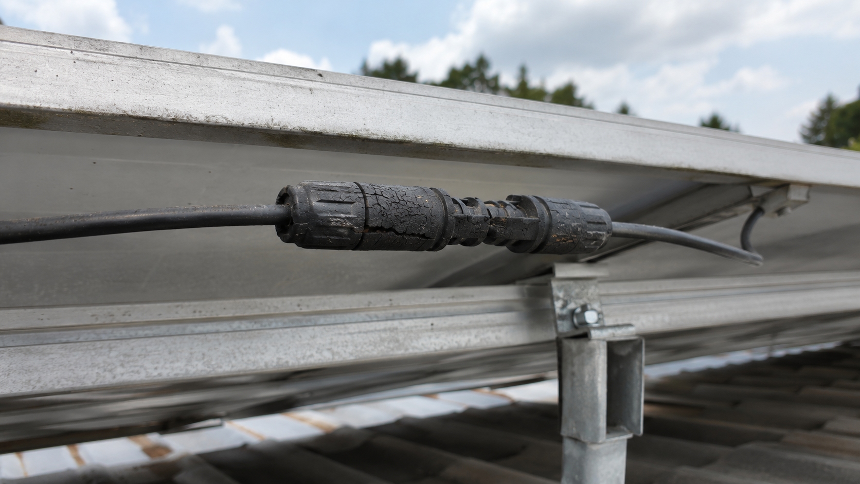
When to Inspect More Connectors
Expand the inspection when:
- Several connectors crack in the same place.
- Multiple connectors show heat damage.
- Different connector families have been mixed.
- Failures are concentrated on one tracker section.
- One cable type repeatedly moves inside the gland.
- Water is found inside several connectors.
- The same production batch appears in each failure.
- Thermal scans show a repeated hot-connector pattern.
- A replacement connector fails again.
Start with the same string, then inspect the same row or tracker unit, the same connector-and-cable combination, work completed by the same installation team, and all connectors from the same batch.
For example, if 6 cracked connectors are found in a sample of 120 inspected connectors, the visible failure rate in that sample is 5%. This does not prove that 5% of the whole plant has failed, but it is enough to justify a wider inspection of the same model, batch, cable type, or installation group.
A 2025 U.S. national laboratory model for a 100 MW PV plant estimated that connector-related work could add about $71,933 per year in operation and maintenance cost in the example plant. The report also estimated about $1.49 million in connector-related lifetime O&M net present value. These are model results for one example, not general costs for every project.[7]