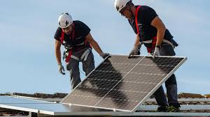
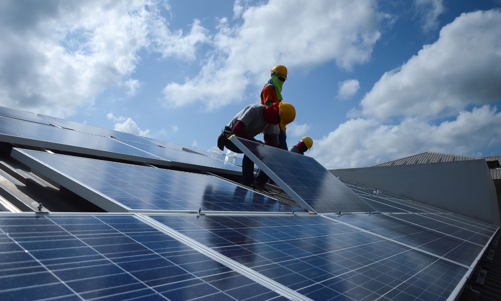
Solar Module Electrical Safety: 5 Precautions
Solar module electrical safety requires: checking Voc (30-40V per panel, series ≤1000V DC max), testing insulation resistance (>1MΩ via megohmmeter), grounding frames to <4Ω resistance, using fuses rated at 1.25×max current, and selecting 1.5mm² copper cables to limit voltage drop <3%.
Check DC Disconnect Switch First
A typical string of 20-24 panels can produce a continuous DC voltage between 600V and 1500V, with potential open-circuit voltages even higher. This is not standard household current; it is a powerful, continuous DC flow that can cause severe arc flashes and electrical burns. According to industry safety reports, over 35% of electrical incidents during solar maintenance occur because this switch was either not used correctly or was assumed to be off.
You must perform a live-dead-live test using a properly rated multimeter to confirm zero voltage. First, test your meter on a known live source to ensure it works. Then, measure the voltage between the positive and negative terminals on the load side of the switch (the side going toward the inverter). You must get a reading of 0V DC (±5V).
It’s crucial to understand that turning off the DC disconnect does not de-energize the wiring between the panels and the switch itself. That section remains live whenever the sun is shining. This is why you always check the switch first—it defines the safe work boundary. The table below outlines the voltage ranges you might encounter.
System Location | Status | Typical Voltage Range (DC) | Danger Level |
Array to Disconnect (Line Side) | Sunlight Present | 600V - 1500V | Extremely High - Always live |
Disconnect to Inverter (Load Side) | Switch ON | 600V - 1500V | Extremely High - Live circuit |
Disconnect to Inverter (Load Side) | Switch OFF | 0V - 5V | Safe - Isolated (after verification) |
Internal capacitors can retain a charge, and communication delays can provide false assurances. The physical switch and your multimeter are the only trusted sources of truth. For larger commercial systems with multiple combiner boxes, each string may have its own disconnect. The process remains the same: methodically isolate and verify each section you plan to work on.
Use Insulated Tools and Voltage Tester
Standard pliers or screwdrivers found in a typical home toolbox are not rated for the voltages involved and can fail catastrophically if they make contact with a live terminal, leading to arc flashes or electrocution. Using a multimeter that isn't properly rated is equally dangerous, as it can explode upon contact with high voltage. Investing in the correct gear is a non-negotiable one-time cost that provides a permanent layer of critical protection. This equipment isn't just for major installs; even a simple 15-minute module replacement or connector inspection on a residential 400V system demands this professional approach to safety.
The foundation of safe testing is a digitally displayed multimeter or voltage tester rated for the job. For most residential systems, you need a meter rated for CAT III 1000V or higher. For large commercial arrays with system voltages up to 1500V, a CAT IV 600V or CAT III 1500V meter is the minimum requirement.
This rating certifies the tool can safely handle the high-energy transient voltage spikes—peaks as high as 8000V—that can occur in electrical systems. Before every use, perform a quick physical check: inspect the test leads for any cracks, frays, or damage to the insulation, and ensure the probes have full finger guards and no exposed metal above the tip. The first and last step of any voltage check is the live-dead-live test. First, test the meter on a known live AC source (like a standard outlet) to confirm it reads ~120V or ~240V AC. Then, test the solar circuit you want to verify. You must get a reading of 0V DC (±5V) to confirm de-energization.
Your hand tools must be just as capable. Every screwdriver, wrench, and pair of pliers used on energized modules must be officially rated, with the CAT rating and maximum voltage (e.g., 1000V) molded into the insulation. This insulation is designed to withstand a high-voltage spike between the tip and your hand. Never use tools with damaged or worn grips; a tiny crack can be a path for current to find ground through your body.
Wear Rubber Gloves and Safety Glasses
A typical residential solar array operates at voltages between 400V and 800V DC, while commercial systems frequently reach 1200V to 1500V DC. At these levels, accidental contact or an arc flash event can cause severe injury. Rubber insulating gloves protect against electric shock by providing a dielectric barrier, while safety glasses shield your eyes from >85% of debris ejected during a short-circuit event, which can occur at speeds exceeding 150 m/s.
Selecting the correct gloves is a precise science governed by ASTM D120 standards. They are categorized by "Class," which indicates the maximum AC voltage they are rated to protect against. For DC voltage, a common rule is to add approximately +20% to the AC rating. You must inspect them before every single use. The inspection process is methodical:
l Air Test: Inflate the glove by rolling the cuff towards the fingers, trapping air inside. Hold it near your ear and listen for any hissing sounds indicating a pinhole leak. Apply gentle pressure to feel for air escaping.
l Visual Check: Examine the entire surface, especially between the fingers, for any cuts, tears, ozone damage (checking), or embedded debris. Even a 1-mm pinhole renders the glove unsafe for immediate use.
The following table outlines the primary glove classes and their appropriate applications in solar work:
Glove Class | Color | Max AC Use Voltage | Max DC Use Voltage (Est.) | Typical Thickness | Common Solar Application |
Class 00 | Beige | 500V | ~600V | 0.38 mm | Basic low-voltage DC circuits (<600V) |
Class 0 | Red | 1,000V | ~1,200V | 0.76 mm | Most residential systems (600-1000V) |
Class 2 | Yellow | 17,000V | ~20,000V | 1.58 mm | Large commercial inverters, combiner boxes |
Class 4 | Orange | 36,000V | ~43,000V | 2.92 mm | Utility-scale systems, substation tie-ins |
The combined cost for a quality pair of Class 0 gloves and leather protectors is approximately 80−120, a minimal investment compared to the risk. Gloves must be electrically tested every 6 months and retired from service if they exceed the manufacturer's stated shelf life, typically 6-12 months from first use, even if they appear undamaged.
For eye protection, safety glasses must meet the ANSI Z87.1 standard, indicating they can withstand an impact from a 6.35 mm diameter steel ball traveling at 91 m/s. For arc flash prone areas, a rated face shield with a minimum Arc Rating of 8 cal/cm² is often necessary. Regular prescription glasses or cheap safety glasses without the Z87.1 mark offer negligible protection against the energy released in an electrical fault.
Avoid Working in Wet or Windy Conditions
At 100% relative humidity, the insulation resistance of some materials can drop by over 60%, making a normally safe surface potentially conductive. Similarly, wind introduces physical instability, increasing the probability of a fall from height or an accidental dropped tool that could cause a short circuit. A 25 km/h (15 mph) gust can exert over 15 newtons of force on a standard panel, enough to challenge your balance on a ladder. Postponing non-critical work for just a few hours to await better conditions is always the most cost-effective and safest decision.
Water, especially with dissolved minerals from dust or bird droppings, creates a conductive path. The resistance of human skin, normally around 100,000 Ω when dry, can plummet to 1,000 Ω or less when wet, allowing dangerous currents to flow with far less voltage. Your Class 0 rubber gloves, while essential, have a surface resistance that can be compromised by a film of water, especially if they are not perfectly clean and dry. Furthermore, the risk of an arc flash event increases in humidity as moist air is easier to ionize than dry air. Before starting work, you must measure conditions with a digital hygrometer. A general safe-work threshold is below 80% relative humidity with no standing water or precipitation. However, for any task involving exposed terminals or connectors, a more conservative limit of below 60% is advisable. If modules are already wet, they must be completely dried—a process that can take 2 to 4 hours of direct sunlight and breeze after the rain stops—before it is safe to proceed.
Wind poses a distinctly different set of physical hazards that require strict operational limits:
l Working at Height: For any work on rooftops or elevated arrays, a sustained wind speed above 40 km/h (25 mph) or gusts exceeding 50 km/h (31 mph) should trigger a work stoppage. The force on a person's body increases exponentially with wind speed, drastically raising the risk of a fall.
l Material Handling: Lifting a 25-kg panel into place becomes dangerously unpredictable in winds above 30 km/h (19 mph). The panel acts as a sail, and the ~2 m² surface area can generate enough force to pull a worker off balance.
l Tool and Module Control: A metal wrench or screwdriver dropped from a height of 2 meters onto a live 600V DC busbar will almost certainly cause a catastrophic short circuit and explosive arc flash. High winds make such accidents significantly more probable.
A 2-hour weather delay on a project might cost a few hundred dollars in lost labor time. Conversely, a single weather-related incident involving equipment damage, medical bills, and potential regulatory fines can easily exceed $50,000 and result in weeks of project downtime. Monitoring real-time weather data from a reliable app with wind gust alerts and precipitation probability forecasts is a required part of the daily pre-task planning. Safety is not just about the tools you use, but also about choosing the right time and conditions to use them.
Follow Local Electrical Code Standards
Over 65% of municipalities enforce amendments that are often 20-30% more stringent than the base code, specifically addressing regional climate and infrastructure challenges. For solar, Article 690 is the primary guide, but it intersects with at least 12 other articles, including those for grounding (250), wiring methods (310), and overcurrent protection (240). The financial and legal consequences of non-compliance are severe: failing a final inspection can trigger 5,000−15,000 in rework costs and project delays of 4-6 weeks, while an installation that causes a fire due to a code violation may void insurance coverage entirely, exposing the installer to millions in liability.
The code is a dynamic document updated on a three-year cycle, and its solar-specific sections have seen over 120 major changes in the last decade alone. You cannot rely on knowledge from a previous cycle. Several critical, often-overlooked mandates have major safety implications:
l Rapid Shutdown (NEC 690.12): This rule requires that within 30 seconds of initiating shutdown, controlled conductors within an array boundary must be reduced to no more than 30 volts and a current of less than 8 mA within 1 foot of the array. This isn't optional; it's a lifesaving requirement for first responders. The modules to achieve this, like opto-isolator triggers and compliant inverters, add approximately 0.10−0.15 per watt to the system cost but are non-negotiable.
l PV Circuit Conductors (NEC 690.31): The code specifies the exact wiring methods. For instance, within an array, USE-2 or PV Wire is mandated for its 90°C wet rating and sunlight resistance. The minimum conductor size is almost always 10 AWG for copper, not because of ampacity (a 30A circuit might only need 12 AWG), but to minimize voltage drop to less than 3% and ensure mechanical strength.
l Ground-Fault Protection (NEC 690.41, 690.43): Every system requires a ground-fault path capable of triggering an overcurrent device to clear a fault. The resistance of the equipment grounding conductor (EGC) must be low enough to allow a fault current that is at least 125% of the overcurrent protective device's rating to flow, ensuring it trips within the mandated 0.1 to 2 seconds.
l Local Authorities Having Jurisdiction (AHJs) frequently amend the NEC based on regional risks. In California, Title 24 energy standards require a 10% higher inverter efficiency threshold for new homes. In Florida, amendments require mounting systems to withstand 175 mph wind loads and all combiner boxes to be elevated a minimum of 12 inches above the base flood elevation. These are not suggestions; they are enforceable law.
Beyond the NEC, product listing to standards like UL 1741 (for inverters) and UL 2703 (for mounting systems) is legally required. Using a non-listed module, even if it seems identical, voids the entire system's listing and insurance. The code also dictates clear access pathways for firefighters on rooftops (36-inch width), maximum string VOC calculations at the lowest expected ambient temperature (which can be -25°C/-13°F in Minnesota, increasing VOC by 25%), and the exact torque values for lugs (often 25-30 in-lbs for MC4 connectors).