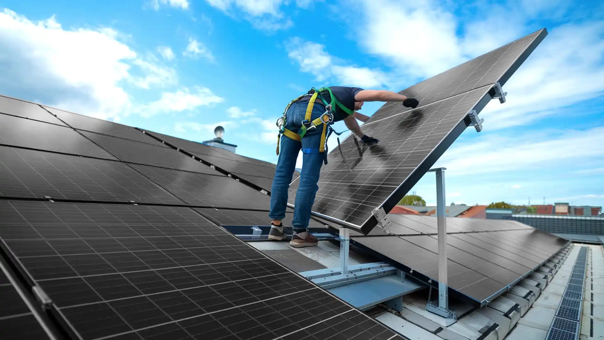
What Maintenance is Required for Polycrystalline Solar Panels?
It is recommended to wipe accumulated dust with clean water every six months, which can improve power generation efficiency by about 10%. Self-inspection of bracket firmness and module cracks is required annually.
If monitoring shows an abnormal drop in daily power generation exceeding 15%, hot spot failures should be investigated. Adhering to scientific maintenance ensures the stable operation of the power station for over 25 years.
Surface Dust Removal
Choosing the Time
The 3.2 mm ultra-white cloth-patterned tempered glass on the surface of polycrystalline silicon panels is extremely sensitive to thermal stress. When the temperature difference caused by uneven heating on the glass surface exceeds 22 °C, internal stress will quickly soar from 50 MPa, increasing the risk of physical explosion.
Between 12:00 and 14:00 at noon in summer, the center temperature of the panels often reaches 65 °C to 75 °C. If normal temperature tap water at 20 °C is used for direct rinsing at this time, the instantaneous strong temperature difference of over 45 °C will cause micro-cracks invisible to the naked eye in the glass.
These micro-cracks will cause the 120 nm thick anti-reflective coating (ARC) to peel off within 18 months, leading to a decrease in light transmittance by 3% to 5% and directly reducing the single-panel output power by more than 15 W.
It is suggested to strictly control the cleaning window between 06:00 and 08:30 in the morning or after 18:00 in the afternoon. At these times, the module surface temperature is maintained below 30 °C, and the temperature difference with the cleaning water is less than 10 °C, ensuring packaging reliability for 25 years.
Based on an annual natural attenuation rate of 0.5%, choosing a reasonable cleaning time can keep the system's power generation above 92.5% of the initial rated value even after 10 years.
Water Quality Parameters
The Total Dissolved Solids (TDS) content of the cleaning water is a key indicator of maintenance quality.
When high-hardness groundwater with a TDS value exceeding 250 mg/L is used, a calcium and magnesium scale layer with a thickness of about 0.1 mm will remain on the polycrystalline silicon surface after water evaporation.
This white scale layer will reflect more than 8% of incident photons, reducing the actual output of cells with 17% conversion efficiency to about 15.5%.
Under long-term accumulation, a 0.5 mm thick salt scale will reduce the photoelectric response speed of the modules by 12% and generate 2 to 3 W of additional heat loss due to increased impedance.
· TDS Limit: Cleaning water TDS must be lower than 50 mg/L to prevent the formation of permanent mineral spots.
· pH Value: The water pH value should be stable between 6.5 and 7.5. Strong acid (pH < 5) or strong alkali (pH > 9) will corrode the 15 μm thick anodic oxide layer of the aluminum alloy frame.
· Resistivity: Industrial-grade cleaning is recommended to use deionized water with a resistivity greater than 0.1 MΩ·cm to ensure no residual charge on the surface after washing.
· Flow Control: Rinsing pressure should be set between 0.3 to 0.5 MPa, and the flow rate should be maintained at 5 to 8 L/min to avoid high-pressure water flow impacting the junction box sealant.
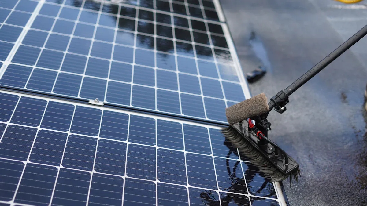
Cleaning Tools Selection
The Mohs hardness of the polycrystalline silicon panel surface is usually between 5 and 6. The physical properties of maintenance tools directly determine the survival life of the 120 nm anti-reflective coating.
It is strictly forbidden to use metal scrapers or hard plastic brushes with a Mohs hardness exceeding 3.5. Under a thrust of 20 N, such tools will produce scratches with a depth of about 50 nm, increasing the diffuse reflectance of the glass surface by more than 2%, leading to a 10% decrease in the absorption efficiency of low-angle light in the early morning and evening.
· Fiber Density: Microfiber lint-free cloths with a weight of more than 250 gsm must be used, with a fiber diameter of only 5 μm.
· Brush Flexibility: The brush diameter of automatic cleaning robots should be controlled between 0.08 and 0.12 mm, and the pressure of a single brush must not exceed 0.5 N.
· Solvent Ratio: In case of oily accumulation, a 1% concentration of neutral isopropyl alcohol solution can be used. Glass cleaners with an ammonia content exceeding 0.5% are strictly prohibited.
· Friction Coefficient: The dynamic friction coefficient during cleaning should be kept below 0.3 to reduce mechanical pull on the silicone sealant at the 35 mm frame.
Avoid Shadows
Partial shading is fatal to polycrystalline silicon systems. A patch of dried bird droppings or thick mud spots with an area of only 25 cm² will cause the series resistance of the cells in that area to soar from 0.1 Ω to over 5 Ω.
Since the internal electron mobility of polycrystalline silicon is about 1450 cm²/(V·s), the shaded area will transform from a power generation unit into a power-consuming load, converting electrical energy into heat, and the local temperature can rise to over 120 °C within 15 minutes.
This hot spot effect will force bypass diodes to operate at 100% load, shortening their 15-year design life to less than 5 years.
· Temperature Rise Threshold: If a certain point is found to be 15 °C higher than the average temperature of the whole board during inspection, it is judged as an effective shading hot spot.
· Diode Loss: The working heat loss of the diode caused by long-term shading accounts for about 0.8% to 1.2% of the output power of a single board.
· Cleaning Standard: After maintenance, the surface must be 100% free of visible shadows to ensure that the current mismatch loss of the 72 series-connected cell cells is lower than 2%.
· Detection Frequency: For areas with frequent bird activity, perform a 100% coverage spot check every 15 days to prevent the internal busbars of the modules from burning out.
Check the Weather
Rainfall is not equivalent to automatic maintenance. Showers with less than 5 mm of rainfall often mix with PM10 large particle dust on the surface to form mud, which dries to form mud belts up to 2 mm thick at the edges of 10-degree tilts.
This mud belt will block the light-receiving surface at the bottom of the cell cells, causing current limiting within the string, making the output current of the entire string align with the lowest point, and the power drop can reach more than 20%.
· Self-cleaning threshold: Only heavy rain lasting more than 30 minutes with rainfall greater than 20 mm can wash away more than 85% of floating dust.
· Environmental Indicators: When the Air Quality Index (AQI) exceeds 200 for 5 consecutive days, or the PM2.5 concentration is greater than 150 μg/m³, manual intervention must be carried out within 24 hours after rain.
· Wind Speed Impact: After windy weather with speeds above 12 m/s, the change in glass surface roughness must be checked due to the abrasive effect of sand and dust.
· Humidity Fluctuations: In areas where humidity is higher than 85% for a long time, dust removal should be combined with a 0.5% concentration of germicide to prevent the formation of a 50 μm thick biofilm or mold on the glass surface.
Debris Removal
Trimming Branches
In areas with sufficient precipitation, the annual height growth rate of broad-leaved trees can reach 0.5 m to 1.2 m.
A shrub 5 m away from the panel array with a height of 3 m will cast a shadow longer than 6 m when the solar altitude angle is only 25° on the winter solstice, causing power generation efficiency to drop to zero after 15:00.
To ensure that the standard irradiance of 1,000 W/m² can fully act on the polycrystalline silicon surface, a "clearance zone" with a radius 3 times the panel installation height must be established.
If branches are less than 2 m from the panel, the kinetic energy of branches swinging and physically hitting the 3.2 mm tempered glass when the wind reaches level 6 (about 12 m/s) is enough to cause micro-cracks. These cracks will increase the breakage rate of cells by 15% after more than 50 thermal expansion and contraction cycles.
Maintenance Parameter Standards: It is recommended to perform a vegetation coverage assessment every 180 days to ensure that within the full solar trajectory (from azimuth 75° to 285°), no solid obstacles enter the 180-degree field of view in front of the array.
Preventing Bird Droppings
Bird droppings contain high concentrations of uric acid and phosphate, with a pH usually between 3.0 and 4.5.
When these acidic substances adhere to the 120 nm thick silicon dioxide (SiO₂) anti-reflective coating and continue to act at a high temperature of 60 °C for 72 hours, a chemical etching effect will be triggered.
This etching will make the glass surface rough, increasing the light reflectance and reducing the number of effective photons entering the cells by more than 5%.
More seriously, dried bird droppings have extremely strong adhesion, with a physical thickness usually between 1 mm and 3 mm. This thickness is enough to block more than 95% of the infrared spectrum absorption, forming an extremely high-resistance fault point in 72 series cells and forcing the bypass diode to turn on.
Risk Quantification: A long-term bird dropping hot spot will cause the corresponding bypass diode to work continuously under 100% load, raising its junction temperature to about 150 °C, directly leading to diode breakdown failure within 12 to 18 months.
Measuring Temperature Difference
On sunny days with irradiance greater than 600 W/m², the temperature difference between normally operating polycrystalline silicon cell cells should not exceed 2 °C.
If an obvious "bright spot" is observed on the thermal imager screen, and the temperature at that point is more than 15 °C higher than the surroundings, it indicates the presence of invisible tiny debris (such as transparent plastic film residues or small branches).
This temperature difference indicates that the output power of the area has dropped by at least 20% and is enduring a heat flux density exceeding 2000 W/m².
Under long-term thermal imbalance, the silver busbars inside the cells will break due to thermal fatigue, increasing contact resistance and forming a vicious cycle.
Detection Technical Specification: Thermal imaging detection should cover 100% of the light-receiving surface of the panel. If a temperature difference exceeding 20 °C is found within a single module, it must be shut down for cleaning immediately, otherwise the insulation performance of the module will drop from 40 MΩ to below 1 MΩ within 36 months.
Snow Clearing
Monitoring Pressure
The physical structure of polycrystalline silicon panels consists of 3.2 mm thick tempered glass, an EVA encapsulation layer, and solar cells. Its design static load standard is usually 5400 Pa on the front, equivalent to bearing a weight of about 550 kg per square meter.
In snowy weather, the density of fresh snow is about 50 to 100 kg/m³, but as the snow is compressed and moisture condenses, the density of wet snow will rapidly soar to 300 to 500 kg/m³.
When the snow thickness on the panel surface exceeds 30 cm, the force per square meter will reach more than 1500 Pa. Although it hasn't exceeded the 5400 Pa limit, unevenly distributed snow piles will cause local pressure differences.
This non-uniform pressure will cause polycrystalline silicon wafers with a thickness of only 180 μm to produce slight deflection, increasing the risk of micro-cracks by 10% to 15%, causing the power attenuation rate in the next 10 years to increase from the normal 0.5% to 1.2%.
Snow Type | Density Range (kg/m³) | Pressure at 20cm Thickness (Pa) | Physical Risk to 3.2mm Glass |
Fresh Dry Snow | 50 - 100 | 100 - 200 | Extremely low, mainly shading loss |
Wet/Mixed Snow | 200 - 400 | 400 - 800 | Moderate, may induce frame deformation |
Compacted Snow/Ice | 500 - 800 | 1000 - 1600 | High, long-term load leads to cell micro-cracks |
Blocking Bright Light
The absorption of light by polycrystalline silicon cells is mainly concentrated in the wavelength range of 300 nm to 1100 nm.
Snow is an excellent optical shielding layer. When the thickness reaches 5 cm, the light transmittance will drop below 1%, meaning the panel is basically in a zero-output state.
Even if the snow only covers 10% of the panel's bottom area, since polycrystalline silicon modules usually adopt a circuit design of 60 or 72 cells in series, the current obstruction of the bottom cells will force the current (Imp) of the entire string to drop synchronously.
At this time, to prevent the shaded cells from overheating, the bypass diode will force intervention and turn on, which will cause a 33% or 66% instantaneous power loss.
Frequent long-term triggering of the diode will cause its junction temperature to exceed 150 °C, shortening the 15-year design life to about 6 years.
Snow Thickness (cm) | Light Transmittance (%) | Expected Power Ratio (%) | System Status |
0 | 100 | 100 | Rated Output |
1 - 2 | 20 - 30 | 15 - 25 | Low Efficiency, Current Mismatch |
> 5 | < 1 | 0 | System Shutdown / Bypass Working |
Choosing Equipment
The Mohs hardness of the polycrystalline silicon panel surface is 5 to 6, while the 120 nm thick anti-reflective coating (ARC) is extremely fragile.
Using a metal shovel or hard plastic scraper to move across the panel will produce physical scratches with a depth of about 30 nm.
These scratches appear as serrated gullies when magnified 500 times, increasing diffuse reflection of light by 2% to 4%, leading to a lower probability of photons entering the cells.
It is recommended to use soft nylon brushes with a bristle diameter below 0.1 mm or foam scrapers with long handles.
The downward pressure during operation should be controlled between 5 and 10 N, ensuring that while removing more than 95% of the snow, it does not produce a transient displacement of more than 2 mm on the 35 mm aluminum alloy frame.
Do Not Splash Water
In winter, the ambient temperature of polycrystalline silicon panels is usually below -10 °C. If warm water above 40 °C is splashed to melt snow quickly, the instantaneous 50 °C temperature difference will generate huge thermal stress.
When this thermal stress exceeds the tensile strength of 50 MPa inside the tempered glass, it will cause the glass to burst.
Furthermore, if water enters the gap between the aluminum alloy frame and the silicone sealing strip and freezes again at night, the mechanical force generated by its 9% volume expansion will pry open the encapsulation layer, increasing water vapor permeability by 20 times, leading to the early termination of the 25-year module life within just 3 winters due to the PID (Potential Induced Degradation) effect.
Ambient Temp (°C) | Water Temp Limit (°C) | Max Allowed Temp Diff (°C) | Glass Burst Probability |
-20 | Not Recommended | < 5 | Extremely High |
-10 | < 0 (Cold Water) | < 10 | Moderate |
0 | < 15 | < 15 | Low |
Finding the Angle
The static friction coefficient of the polycrystalline silicon panel surface is about 0.3 to 0.5 in a dry state.
When the installation angle is greater than 35°, the snow will slide off as a whole under the action of its own weight as long as a 0.1 mm water film is generated at the bottom.
However, in systems with small tilt angles of 15° to 25°, snow often accumulates at the frame, reaching a thickness of more than 10 cm.
These residual snow blocks will form ice dams during the melting process, hindering the subsequent drainage of snowmelt, and causing the frame to be soaked in weakly acidic snowmelt with a pH of about 5.6 for a long time.
During maintenance, priority should be given to clearing the "snow platform" at the bottom of the module. Once the mechanical support points at the bottom are destroyed, the snow on the upper 70% of the area will usually achieve self-cleaning using gravity.