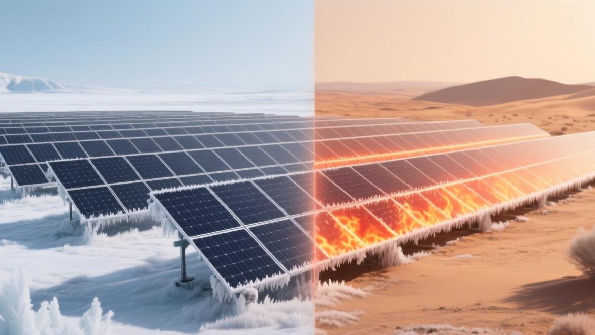
How Do Temperature Variations Affect Solar Cell Performance
Rising temperatures decrease solar cell efficiency.
Using 25°C as a baseline, for every 1°C increase in panel temperature, the photoelectric conversion efficiency drops by approximately 0.4%.
During actual installation, it is necessary to reserve a ventilation gap at the back of the photovoltaic panels or install a water-cooling system to reduce the temperature in order to maintain optimal power generation.
Voltage Drop
Rapid Voltage Drop in Hot Weather
The physical mechanism by which solar panels generate electricity under illumination relies on the P-N junction within the semiconductor. When the ambient temperature climbs from 25°C to 65°C, the thermal vibration of atoms inside the silicon crystal intensifies, causing the bandgap of the semiconductor material to narrow from 1.12 electron volts to around 1.08 electron volts. After absorbing thermal energy, electrons can cross the energy gap more easily, and the intrinsic carrier concentration experiences exponential growth.
The increase in intrinsic carrier concentration significantly doubles the reverse saturation current of the P-N junction. For every order of magnitude increase in the reverse saturation current, the open-circuit voltage of a single silicon cell decreases by about 60 millivolts. For conventional P-type monocrystalline silicon cells, which currently have a 90% market penetration rate, the voltage of a single cell will drop by 2.1 to 2.3 millivolts for every 1°C increase in the rated temperature.
For a standard large commercial module packaged with 72 cells in series, its overall voltage temperature coefficient is typically rated at negative 0.28% per degree Celsius. When the panel's physical operating temperature reaches an extremely hot state of 70°C, compared to the 25°C laboratory test baseline, the open-circuit voltage of the entire panel will evaporate by 6.5 volts to 7.5 volts out of thin air.
Mischief of Dark Current
High-density thermally excited electrons form a dark current inside the cell that is exactly opposite to the direction of the photogenerated current. For every 10°C increase in ambient temperature, the value of the dark current is magnified by about twofold.
The dark current frantically consumes the effective charge that should have been output to the external circuit, causing the fill factor (which evaluates the panel's output quality) to plummet from a high of 0.80 down to around 0.73. The deterioration of the fill factor creates a superimposed reaction with the voltage plunge.
A solar panel with a rated peak power of 450 watts has a nominal maximum power point voltage of 41.5 volts and a maximum power point current of 10.84 amperes under standard test conditions.
Under afternoon sun exposure reaching 65°C, the operating voltage drops to only 35.8 volts. Even if the short-circuit current slightly increases to 10.9 amperes due to the widening of the beam absorption band, the actual output power obtained by multiplying the two is only about 390 watts.
Within the rated output budget, 60 watts of power are completely dissipated into the air in the form of waste heat, causing a single panel to suffer an additional loss of 0.24 kilowatt-hours of yield during the 4-hour high-irradiation period at noon every day.
Narrow Voltage Window
A photovoltaic inverter is responsible for converting direct current into alternating current, and it contains an internal maximum power point tracking (MPPT) system. Each inverter is set with an MPPT voltage operating range before leaving the factory, usually between 200 volts and 800 volts.
When 15 modules with a nominal operating voltage of 40 volts are connected in series to form an array, at a temperature of 25°C, the total input voltage of the array is 600 volts. This falls perfectly within the optimal conversion efficiency range of 550 volts to 650 volts set by the inverter, allowing the inverter to maintain its highest electrical energy conversion rate of 98.6%.
When summer ambient temperatures soar and the surface temperature of roof panels reaches 75°C, the massive 50°C temperature difference will cause the voltage of a single module to drop to 32 volts, and the total voltage of the 15 modules in series will consequently plummet to 480 volts.
The input value of 480 volts completely deviates from the inverter's optimal efficiency range, forcing the inverter's conversion rate to drop to 95.2%. The double energy loss from the front-end module voltage drop combined with the back-end inverter efficiency decline will cause the overall power generation data of the entire photovoltaic power station to experience a 15% cliff-like decline during the midsummer peak period.
Calculating the Number of Panels
To avoid the risk of equipment shutdown caused by high temperature and low voltage, when wiring the electrical system topology, the absolute maximum temperature data recorded over the past 20 years at the project location must be used to reversely deduce the series quantity.
Assuming the extreme maximum temperature in a desert climate zone reaches 48°C, and considering the heat accumulation brought by solar radiation, the actual maximum operating temperature of the panel will be set as an 80°C calculation boundary. Calculations show that the extreme minimum operating voltage of a single module might be only 29 volts.
If the centralized inverter used has a startup voltage threshold of 500 volts, a single string array needs to connect at least 18 modules to ensure that the system can still successfully wake up and connect to the grid for power generation under extreme heat waves.
If only 14 modules are connected in series based on the conventional parameters of 25°C, the total voltage of the array in hot weather will only be 406 volts. This is completely incapable of triggering the inverter's startup sequence, resulting in the entire array entering a shutdown state with zero power output during the noon period when lighting conditions are most abundant and power generation potential is greatest, wasting at least $40 in potential electricity sales revenue every day.
Junction Box Leakage
The junction box installed on the back of the module encapsulates bypass diodes inside, which are used to conduct current when blocked by leaves or covered by dust, preventing the hot spot effect from burning out the entire panel.
The electrical parameters of Schottky bypass diodes are extremely sensitive to temperature. In a 40°C environment, the reverse leakage current of the diode is only 3 milliamperes.
Because the junction box is closely attached to the heating cell backsheet, its internal accumulated temperature can easily exceed 90°C. Under the roasting heat of 90°C, the reverse leakage current of the diode will sharply soar to 35 milliamperes or even higher levels.
The high leakage current under a reverse bias voltage of up to 40 volts will continuously consume the usable electrical energy generated by the panel.
The high-temperature leakage loss within a single junction box alone can reach 1.4 watts. For a medium-sized commercial distributed power station with 5,000 panels, simply due to this single physical change of diode high-temperature leakage, 7 kilowatt-hours of usable electricity will evaporate into thin air every hour.
Thermal Cycling and Degradation
During the day under direct sunlight, the physical surface temperature of the solar panel will rapidly climb to 70°C or even 75°C. At night, without illumination, the panel temperature will plunge along with the ambient air temperature to below 10°C. In some arid desert climate zones, night temperatures can even drop below minus 5°C.
This huge daily temperature difference fluctuation of up to 80°C forces all the materials inside the panel to undergo a drastic physical expansion and contraction process every single day.
Because the panel is laminated and bonded from a variety of different materials, such as glass, ethylene-vinyl acetate (EVA) encapsulant film, silicon wafers, copper tinned soldering ribbons, and polymer backsheets, there is a huge numerical difference in the thermal expansion coefficients of each material.
The thermal expansion coefficient of monocrystalline silicon material is only 2.6 parts per million per degree Celsius, while the thermal expansion coefficient of the copper conductive ribbon soldered to the surface of the silicon wafer is as high as 16.5 parts per million per degree Celsius. The nearly 6-fold difference in expansion deformation between the two will generate extremely strong mechanical shear stress on their bonded contact surface.
Under the continuous pulling of 1,000 day-and-night temperature cycles over 3 years, an originally tiny 5-micron micro-crack on the silicon wafer surface will rapidly spread and expand outwards, eventually forming a penetrating crack exceeding 20 millimeters in length. This causes the electron transmission channels in the damaged area to completely break, and the actual output current of a single cell will consequently plummet by 15% to 20%.
The metal interconnect strips responsible for connecting individual cells in series will experience severe metal fatigue degradation under the repeated torture of thermal expansion and contraction. The tin-lead alloy of the solder layer softens at high temperatures and becomes brittle at low temperatures. This repeated switching of physical states will generate a large number of microscopic voids and fine cracks invisible to the naked eye inside the soldering joints.
After about 1,800 cold-hot alternations over a period of 5 years, these tiny voids will gradually merge together, causing the effective contact area of the solder joint to shrink by 40%.
The reduction in contact area directly causes the series contact resistance of that node to climb sharply from the factory 15 milliohms to over 50 milliohms. Calculated based on a conventional operating current of 10 amperes for a module, this single damaged solder joint alone will generate an additional heat loss of 3.5 watts every day due to the increased resistance.
The IEC 61215 standard issued by the International Electrotechnical Commission requires that panels must pass 200 high-low temperature extreme limit cycle tests from minus 40°C to 85°C. After the test, if the module's peak power degradation rate exceeds 5%, that batch of products will be judged as unqualified and unable to enter the commercial procurement list, because this kind of physical fatigue would trigger a total power generation collapse of up to 12% in the 10th year of project operation.
Under the long-term effect of thermal cycling, the internal macromolecular polymer chains of the encapsulant film sandwiched between the glass and the silicon wafer will fracture and degrade.
Especially when the panel temperature continuously exceeds 80°C at summer noon, the internal cross-linking degree of the film will drop from the standard 85% to around 70%, and the originally tightly fitting molecular structure becomes loose. Material degradation will precipitate a large amount of acetic acid gas. This gas cannot escape from inside the sealed glass layer and eventually gathers to form bubbles ranging from 0.5 mm to 2 mm in diameter.
The appearance of bubbles directly destroys the film's original high light transmittance of 99.5%, causing incident light rays to undergo diffuse reflection and refraction on the bubble surface, and reducing the number of effective photons reaching the underlying silicon wafer by about 7%.
For an outdoor centralized photovoltaic array with an installed capacity of 10 megawatts, after 8 full years of service, due to film delamination and light transmittance decline caused by thermal cycling, the overall array's system efficiency typically drops from the initial 82% at grid connection to 76%. The annual electricity sales cash flow revenue will consequently decrease by about an expected budget of $45,000.
After experiencing thousands of expansions and contractions, the crystallinity of the polyethylene terephthalate (PET) or polyvinyl fluoride (PVF) backsheet material will change, and its toughness will decrease sharply. In extremely cold winter mornings at minus 20°C, the backsheet material that has already lost its elasticity is very prone to microscopic physical cracking. Once cracks form, water vapor molecules in the air will penetrate into the panel at a rate of 0.02 grams per day.
When water mixes with the aforementioned acetic acid, it will push the leakage current index up by 300%. This not only accelerates the electrochemical corrosion rate inside the cell, but also greatly increases the probability of the inverter detecting a grounding insulation fault. Once the insulation impedance falls below the 500 kilo-ohm safety threshold set by the inverter, the system will forcefully cut off the grid connection and enter a protective shutdown state.
If a string inverter managing 100 kilowatts of modules shuts down for 2 hours a day due to backsheet leakage, it will cumulatively waste 7,300 kilowatt-hours of production potential over a year. When building a 25-year full life-cycle financial model, this compound mechanical degradation brought by thermal cycling requires investors to set the annual linear degradation rate parameter between 0.55% and 0.65% to calculate a realistic internal rate of return.
Shortened Service Life
Solar cell modules are typically marked with a 25-year linear power warranty when leaving the factory. However, in arid climate zones where long-term daytime maximum temperatures exceed 40°C, the actual physical operating life of the panels will dramatically shrink to about 15 to 18 years.
The rate of physicochemical reactions is strongly positively correlated with ambient temperature. According to reaction kinetics statistical variance models, for every 10°C climb in the operating temperature of the internal materials of the panel, the chemical reaction rate of polymer degradation will double. When the panel operates continuously under extreme high temperatures of 80°C in summer, the aging speed of its internal materials is more than 30 times that under the standard 25°C testing conditions.
Prolonged over-temperature roasting will cause the anti-reflective coating on the silicon wafer surface to peel off prematurely. An originally 75-nanometer thick silicon nitride film, after undergoing five years of high-temperature baking, will wear down to an average thickness of about 60 nanometers, and its surface light wave reflectance will heavily rebound from 2% at the factory to 5%.
The physical attenuation of light transmittance, superimposed with the cell's own electrical degradation, worsens the annual average power degradation rate of the entire panel from the industry standard 0.55% to a range of 0.85% to 1.2%.
In a 50-megawatt commercial-grade ground power station with a pre-set service life of 25 years, if the degradation rate parameter is adjusted upwards by 0.4 percentage points, by the 20th year of project operation, the station's actual rated output power will only be 72% of its initial installed capacity, far below the expected 82% safe passing line.
Discounted Lifespan
A continuous high-temperature load will greatly induce and accelerate the outbreak probability of the Potential Induced Degradation (PID) effect. Under the superimposed effect of an 85°C panel operating temperature and a tropical rainforest climate reaching 85% relative humidity, sodium ions contained in the glass panel will gain extremely high active kinetic energy.
Driven by a system DC bias voltage of up to 1,000 to 1,500 volts, massive amounts of positively charged sodium ions will easily penetrate the thinned encapsulant layer and densely accumulate in large areas within the P-N junction region on the surface of the P-type silicon crystal.
High-concentration sodium ion accumulation will severely damage the internal electric field distribution of the semiconductor, causing serious localized short circuits and causing the leakage current to display logarithmic explosive growth within just 30 days.
l High temperatures cause the migration rate of sodium ions inside the glass layer to increase by about 4.5 times. Electrical degradation problems that originally would have taken 10 years to manifest are forcibly compressed into a concentrated outbreak in the 3rd to 4th year after operation.
l For a solar panel undergoing severe potential induced degradation, its single open-circuit voltage will plummet from 38 volts to below 12 volts, and the effective output power loss ratio of the entire module string can reach as high as 30% to 50%.
l The fault frequency recorded by the inverter detection system surges from 0.2 times per month to 4.5 times per week. High-frequency shutdown errors force the operation and maintenance team to increase their annual inspection budget by 25% for manual troubleshooting.
l To repair a power deviation rate of up to 40%, investors must additionally purchase anti-degradation recovery modules priced at $800 each. By forcefully raising the modules' voltage to ground at night to reversely drive away the sodium ions, the maintenance cost per megawatt is additionally increased by approximately $15,000.
Expensive Panel Replacements
When more than 15% of the panels in an entire photovoltaic array drop by over 20% in power due to thermal losses—crossing the red line limit—evaluating from an economic return rate perspective, the marginal benefit of keeping the old panels generating electricity will no longer cover the fixed losses of system operation. Dismantling and replacing substandard modules that are prematurely scrapped due to high temperatures requires the utilization of a large budget for labor, machinery, and waste disposal.
Taking a medium-sized power station with 10,000 modules as an example, for every 500-watt rated waste panel replaced, in addition to paying an approximately $100 purchase fee for a brand new panel, there is an extra burden of a $35 labor teardown/installation fee, hoisting machinery rental fee, and a $0.5 per kilogram hazardous solid waste environmental disposal fee.
If a major overhaul replacement reaching a 30% scale is carried out prematurely in the 15th year of the system's estimated life, just the two rigid expenditures of equipment depreciation variance and replacement construction costs will cause the project's internal rate of return to plummet from an expected 11% to an alert level of 7.5%.
Project Life Cycle | Average Operating Temperature | Annual Average Degradation Rate | Expected Physical Lifespan | Remaining Power Ratio after 20 Years | Premature Replacement Cost Estimate (Megawatt Scale) | Overall Internal Rate of Return Deviation |
Temperate rated environment | 35°C | 0.50% | 25 years | 84.5% | $12,000 | -0.2% |
Tropical conventional environment | 55°C | 0.75% | 18 years | 76.0% | $45,000 | -1.8% |
Extreme desert environment | 75°C | 1.15% | 12 years | 65.2% | $185,000 | -4.5% |
High temperature and high humidity environment | 80°C | 1.35% | 10 years | 58.6% | $260,000 | -6.2% |
Calculating the Lifespan Accounts
According to a deviation analysis performed on 15 years of actual measurement data from 50 global power stations at the same latitude using a Gaussian distribution statistical model, for every 5°C increase in the median operating ambient temperature, the overall failure-free operating cycle of a photovoltaic system shortens by approximately 2.8 years.
The non-linear lifespan depreciation extremely severely destroys the 10-year static investment payback period set by the initial financial model. Pure electricity sales profits of up to $2.5 million per megawatt, originally expected to be generated between the 11th and 25th years, will heavily shrink by around 40% due to the premature drying and cracking of inverter electrolytic capacitors under high temperatures, thermal breakdown open circuits of diodes inside junction boxes, and large-scale delamination scrapping of the panel body itself.
When preparing the initial capital expenditure budget, financial directors absolutely must not use the 25-year ideal lifespan data provided by laboratories as a multiplier factor to deduce the total life-cycle net present value. Facing harsh construction sites with annual average ambient temperatures greater than 30°C and summer peak temperatures reaching 45°C, they must forcibly accrue an accelerated depreciation reserve of at least 8% on the first year's financial baseline, and advance the calculation node of the asset residual value rate from the original 300th month to the 180th month.
Only by conducting absolute quantified standard deviation corrections on the high-frequency replacement rates, expensive module reset costs, and the risk probability of severely shrinking electricity volumes, can a realistic photovoltaic revenue forecast report with a 95% confidence level be derived. This prevents severe cash flow rupture crises in the later stages of the project caused by underestimating the destructive power of heat.