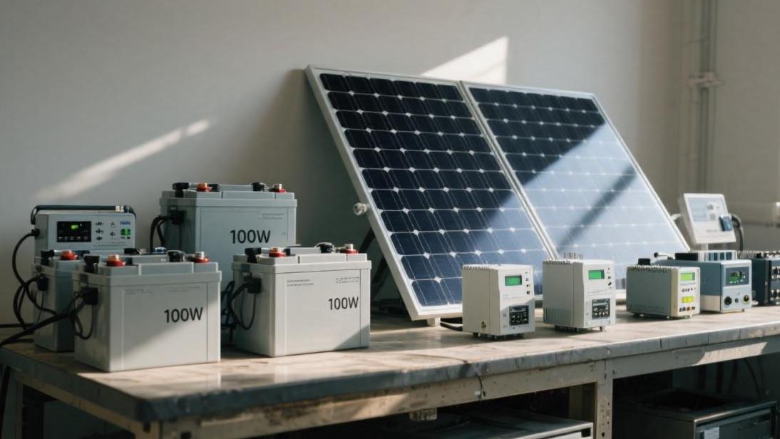
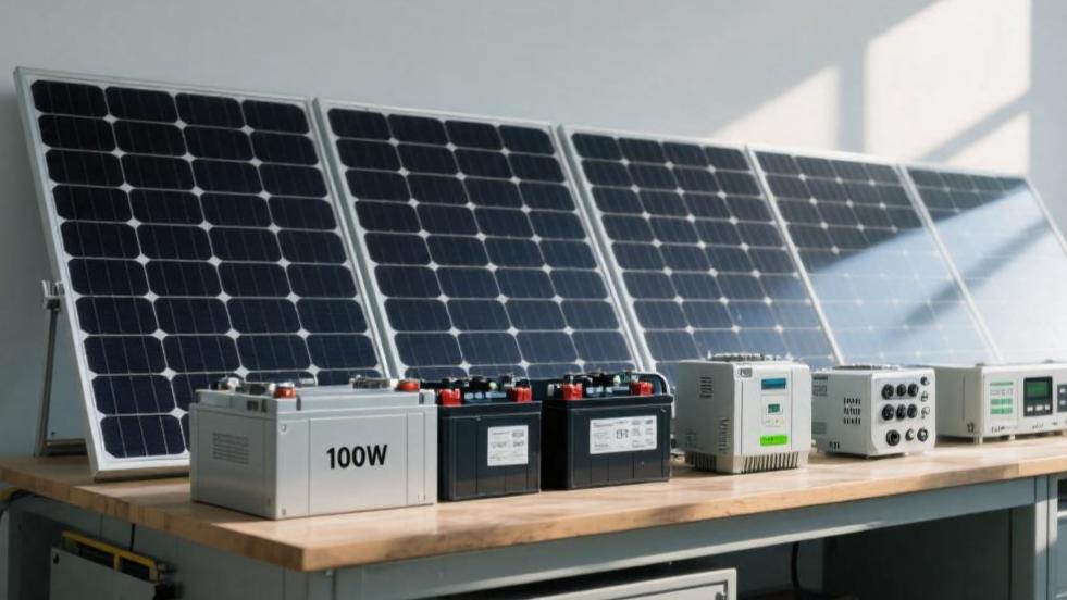
What Equipment Works with 100W Solar Modules | Batteries, Controllers, Inverters
Devices adapted to 100W solar modules include: 12V or 24V batteries, MPPT or PWM charge controllers, and suitable inverter power is 200W to 300W.
When connecting, ensure the controller and cell voltage match, and check the inverter's rated power to prevent overload.
Batteries
Which one is good to choose
The purchase cost of lead-acid batteries is lower. Currently, the price for 12V 100Ah specifications is usually between $100 and $150, but its energy density is very low, and the weight usually reaches 25 kg to 30 kg.
The Depth of Discharge (DoD) of lead-acid batteries is usually suggested to be controlled within 50%. For a lead-acid cell labeled 1200Wh, you can actually use only 600Wh of electricity. If forced to empty, the internal plates of the cell will quickly sulfate, causing the cycle life to shorten to below 20% of the original.
In contrast, although the initial budget for Lithium Iron Phosphate (LiFePO4) batteries is higher, the price for a 12V 100Ah product of the same specification is approximately $250 to $400, but its weight is only 10 kg to 12 kg, and it supports 80% to 90% depth of discharge. Almost all the electricity you buy can be used up. In a 100W solar panel charging environment, the charge-discharge efficiency of LiFePO4 batteries is close to 95%, while lead-acid batteries, because of the electrolysis reaction at the later stage of charging which produces heat loss, usually have an efficiency of only 80% to 85%.
· Weight comparison: Lead-acid about 30 kg/kWh, LiFePO4 about 10-12 kg/kWh.
· Available capacity: Lead-acid suggested use 50%, LiFePO4 available 90%.
· Charge efficiency: Lead-acid about 82%, LiFePO4 about 95%.
· Self-discharge rate: Lead-acid monthly about 5%-10%, LiFePO4 monthly about 2%-3%.
Calculate capacity accurately
The configuration logic of capacity must be determined according to the actual output of the 100W panel. In a sunny environment, the effective power generation duration of a 100W panel per day is calculated as 5 hours, and the output electricity is 500Wh. If you choose a 12V 50Ah LiFePO4 cell, its total energy is 640Wh (12.8V multiplied by 50Ah). Considering the 80% depth of discharge, the available electricity is 512 Wh, which can just completely absorb and store the output of a 100 W panel for one day.
If you blindly expand the capacity to 200Ah, the total energy reaches 2560Wh, then the 100W panel needs 5 consecutive sunny days to fully charge it. In this configuration, the cell is in a semi-depleted state for a long time. Although it will not be damaged as quickly as a lead-acid cell, it will cause the system payback period to stretch from a normal 3 years to over 8 years. Conversely, if the cell capacity is lower than 30 Ah, the high current of 5.5 A around 12:00 noon might trigger the overcurrent protection of the LiFePO4 internal BMS (Cell Management System), or lead to lithium plating inside the cells due to the high charge rate (C-rate), shortening the service life.
· Matching suggestion: 100W panel corresponds to 50Ah-60Ah (12V system) cell.
· Total energy storage: 50Ah lithium cell about 640Wh, 100Ah lithium cell about 1280Wh.
· Charging duration: 100W panel takes about 6-7 hours to fully charge a 50Ah lithium cell (including losses).
· Backup days: 50Ah capacity can usually support basic equipment (phone + lights) for 1.5 days.
Charge and discharge speed
The peak output current of a 100W solar panel is about 5.5A. For a 12V 50Ah cell pack, the charging rate is 5.5A divided by 50Ah, which is about 0.11C. This is a very ideal and gentle charging rate, because the most comfortable charging range for LiFePO4 batteries is between 0.2C and 0.5C.
At the discharge end, if you use a 300W inverter to drive appliances, the current at the cell end will reach about 25A (300W divided by 12V). For a 50Ah cell, this belongs to 0.5C discharge. Most high-quality LiFePO4 batteries support 1C continuous discharge, which is 50A current, but if continuously discharging at a high rate, the actual discharged capacity of the cell will slightly decrease due to internal resistance heat production. Lead-acid batteries perform even worse on this indicator; when the discharge current exceeds 0.1C, due to Peukert's Law, its available capacity will shrink sharply, and an original 50Ah cell might only discharge 35Ah.
· Charging current: 100W panel peak about 5.5A-6A.
· Discharge limit: Suggested continuous discharge current does not exceed 0.5C of the cell capacity.
· Internal resistance loss: LiFePO4 internal resistance is usually less than 20 milliohms, lead-acid is about 50-100 milliohms.
· Voltage performance: Lithium cell discharge platform is stable at 12.8V-13V, lead-acid will slide from 12.6V all the way to 11.5V.
How many years can be used
The cycle count of lead-acid batteries is usually between 300 and 500 times (at 50% depth of discharge). If you use it every day, the capacity will decay to below 80% of the initial value after 1.5 years. While the cycle life of LiFePO4 batteries at 80% depth of discharge is generally above 3000 times, and high-quality cell cells can even reach 5000 to 6000 times. Even if calculated according to one full cycle every day, it can work stably for 8 to 10 years.
Assuming a lead-acid cell costs $100 and can be used 500 times, the cost per use is $0.2; a lithium cell costs $300 and can be used 3000 times, the cost per use is only $0.1. This two-fold gap in cost-performance is the main reason why off-grid systems are fully turning to lithium batteries. In addition, the built-in BMS of LiFePO4 will monitor the voltage balance of single cell cells in real time, preventing scrapping caused by a certain cell's voltage being too high (exceeding 3.65 V) or too low (below 2.5 V).
· Cycle life: Lead-acid 300-500 times, lithium cell 3000-6000 times.
· Capacity decay: Lithium batteries usually still maintain over 90% remaining capacity after 5 years of use.
· Maintenance needs: Lead-acid needs regular checks of liquid levels or ventilation, lithium cell is maintenance-free.
· Protection mechanism: BMS possesses quadruple protection of overcharge, over-discharge, short circuit, and temperature control.
Environmental impact
100W solar panels are usually installed outdoors, but the cell must consider environmental temperature differences. LiFePO4 batteries are prohibited from charging below 0 degrees Celsius. If forced to charge, lithium dendrites will be generated at the anode, which may pierce the separator and lead to a short circuit. Although it can discharge at -20 degrees Celsius, the power will shrink by about 30%. In a high-temperature environment, if the cell working temperature exceeds 45 degrees Celsius, chemical reactions will accelerate; for every 10 degrees Celsius increase, the service life of the cell will be halved.
Lead-acid batteries have slightly better tolerance for low temperatures and can still perform small current charging at minus 10 degrees Celsius, but their deterioration speed at high temperatures is faster than lithium batteries.
Since 100W system controllers usually do not have expensive remote temperature control devices, the best practice is to place the cell in a cool, ventilated storage box, away from direct sunlight. If your usage environment is often below freezing point, you must purchase LiFePO4 batteries with low-temperature heating functions. This kind of cell will use the excess current from the solar panel to heat the cell cells first, and start charging after the temperature rises above 5 degrees Celsius.
· Charging temperature limit: Lithium cell 0℃ to 45℃, lead-acid -15℃ to 45℃.
· Discharge temperature limit: Lithium cell -20℃ to 60℃, lead-acid -20℃ to 50℃.
· Storage suggestion: Ideal environmental temperature is 20℃-25℃.
· High temperature loss: After the environment exceeds 35℃, the cell calendar life decays by about 5%-8% per year.
Controllers
Which type is more worth it
When dealing with 100W solar panels, the first choice you face is PWM (Pulse Width Modulation) or MPPT (Maximum Power Point Tracking) controller. The peak working voltage of a 100W panel is usually around 18V, while the voltage of a 12V cell during the charging process is usually between 12V and 14.4V.
The working principle of a PWM controller is similar to a switch; it forcibly pulls down the voltage of the solar panel to close to the cell voltage, which leads to a power loss of about 25% to 30%. Under the ideal output of 100W, after passing through the PWM controller, the cell end might only receive about 70W of power. Although the price of PWM controllers is extremely low, usually between $15 and $30, its performance is poor in cloudy or low-temperature weather.
The MPPT controller contains a DC transformation process; it can monitor the voltage and current of the solar panel in real time and adjust it to a state that can output maximum power. Even if the solar panel outputs 20V voltage, the MPPT can transform it into the 14V required by the cell, while increasing the charging current proportionally. The conversion efficiency of this method is usually between 96% and 98%, which can obtain about 20W to 25W more actual electricity compared to PWM.
For a small system with only 100W, every watt of electricity is very precious. This extra part of energy is enough to let a 5W LED light stay on for 4 to 5 hours more. Although the price of MPPT is usually above $60, from the perspective of long-term power generation returns, its cost-performance ratio will exceed PWM after 12 months of operation.
Characteristic Parameters | PWM Controller | MPPT Controller |
Conversion efficiency | 70% - 75% | 95% - 98% |
Suitable system | Very low power, low budget | Pursue efficiency, long-term use |
Voltage matching | Panel voltage must be slightly higher than cell | Supports high voltage panel charging low voltage cells |
Average unit price | $15 - $30 | $60 - $150 |
100W actual output | About 70W - 75W | About 95W - 98W |
Amperage must be enough
For a single 100W panel, its maximum output current (Imp) is usually between 5.5A and 5.8A. From the perspective of circuit safety and heat control, you must leave at least 25% redundancy space when choosing a controller. The most common entry specification on the market is 10A, which is a very standard and steady choice for a 100W system.
A 10A controller can carry a maximum input of 120W under a 12V system, and 240W under a 24V system. If you plan to add another 100W panel in parallel in the future, buying a 20A controller now will save more money, because the price of a 20A model is only less than $10 higher than a 10A one, yet it can support a total input power of 240W.
If the chosen current is too small, for example, using a fake-labeled 5A controller to run 5.5A current, the MOS tubes inside the controller will generate a large amount of heat due to long-term full-load operation, and the temperature might quickly soar to above 80 degrees Celsius, which will lead to accelerated aging of electronic modules and even cause the casing to melt.
High-quality controllers usually have a 1.25 times overload tolerance capability and can handle current exceeding the rated value for a short time, but for long-term operation, it is suggested to stay within 80% of the rated value. In addition, the self-consumption (static current) of the controller is also a data indicator; excellent controllers consume only 10 mA to 20 mA of electricity when on standby, and they will only consume about 0.2 Ah to 0.5 Ah of cell capacity for a whole night.
Input Power | System Voltage | Suggested Controller Current | Safety Margin (at 10A) |
100W | 12V | 10A | 45% (Excellent) |
150W | 12V | 15A / 20A | -15% (Unavailable) |
100W | 24V | 10A | 72% (Extremely high) |
200W Parallel | 12V | 20A / 30A | 10% (Relatively low) |
Protection against burning out
When the cell voltage drops to around 11.1 V, the controller will automatically cut off the power supply to the load end to prevent the cell from being completely emptied. This kind of deep discharge is devastating to lead-acid batteries and will also cause BMS lockout for lithium batteries.
Once the sun rises again and the voltage returns to around 12.6V, the controller will automatically restore output. In addition, high-quality controllers integrate reverse current protection functions; when there is no sunlight at night, it can prevent the electricity in the cell from flowing back to the solar panel, preventing unnecessary energy dissipation. If this leakage loss is not controlled, it might drain 3% to 5% of the cell's energy storage every night.
Inverters
Which waveform to choose
In a 100W solar system, the task of the inverter is to convert the 12V DC in the cell into 110V or 220V AC used by household appliances. You will see two main types of inverters on the market: pure sine wave and modified wave. For the vast majority of users, the only one worth buying is the pure sine wave inverter.
The waveform output by a pure sine wave is almost exactly the same as the power grid, and the total harmonic distortion (THD) is usually lower than 3%. It can safely supply power to laptop computers, drone batteries, small medical equipment, and even electric fans with micro motors. Although the price of a 300W pure sine wave inverter is approximately $40 to $60, which is about 50% more expensive than a modified wave inverter of the same power, it can prevent the capacitors inside appliances from overheating or generating harsh current noise.
Modified wave inverters, although cheap, have a current output that jumps in steps, and the harmonic distortion is as high as 20% to 40%. If you use it to charge precise appliances with transformers, you will find the adapter heats up very fast and can even cause internal modules to burn out. For an entry-level system like 100W, the amount of electricity you can use is already very limited; the extra 15% to 20% efficiency loss caused by a modified wave inverter is completely unacceptable. The conversion efficiency of high-quality pure sine wave inverters under rated load can usually reach 88% to 92%. If you output 100W of AC, the cell end actually only spends about 110W of DC.
Core data reference:
· Pure sine wave distortion rate: below 3%
· Modified wave distortion rate: above 20%
· Ideal conversion efficiency: 88% - 93%
· Adapted appliances: all AC appliances (within power range)
What size power
If you match a 150W inverter, although it can drive a laptop, once you want to charge a phone and run a small desktop fan at the same time, the inverter will generate high-frequency noise and heat up severely because it is close to full load. 300W is a very balanced choice; it can ensure operation within the optimal efficiency range of 40% to 60% most of the time, and this load point is usually when the inverter has the least heat production and the longest lifespan.
If you blindly pursue high power, for example, matching a 2000W inverter with a 100W panel, that will be a disaster. More electronic modules are used inside high-power inverters, and their no-load current (that is, the power consumption when turned on without connecting any appliances) will be very startling. The no-load current of a 2000W inverter might reach 1.5A to 2A; even if you do nothing, it will steal about 20Wh of electricity from the cell in one hour. For a 100W system where the daily power generation is only 400Wh to 500Wh, just by keeping it on for 24 hours, the inverter itself could eat up over 80% of the total system power production.
Power matching suggestion:
· Recommended specifications: 300W or 500W
· Suggested maximum load: 80% of rated power
· 100W system upper limit: Not suggested to exceed 1000W
· Load utilization rate: Efficiency is highest when kept at 50%
How much self-consumption
A medium-quality 300W inverter usually has a static current between 0.5A and 0.8A. Converted to power, that is 6W to 10W of electricity consumed in vain every hour. If you forget to turn off the inverter switch, even if you don't plug in any appliances, it will consume 144Wh to 240Wh of energy in the cell for 24 hours a day. Considering the actual effective power generation of a 100W panel is usually only about 400Wh per day, half of the electricity you worked hard to get from the sun is wasted by the inverter standby.
Some high-end inverters have "energy-saving mode" or "search mode"; when detecting a load lower than 5W, it will automatically enter a hibernation state, reducing self-consumption to 10% of the original. In addition, when choosing an inverter, carefully check the no-load current parameter in the manual and choose products lower than 0.6 A. If most of your appliances are USB charging or 12V DC lights, the best way is to connect them directly to the load output end of the controller, completely bypassing the inverter, which can save about 15% of inverter loss.
High starting current
Many devices with motors, such as small car refrigerators, hand-held blenders, or water pumps, will generate extremely high surge currents at the moment of starting, which is usually 3 to 7 times the rated power. For example, a micro refrigerator with a nominal power of 60W might have its peak power soar to 300W or even higher at the moment the compressor starts. If your inverter's rated power is only 150W, even if its nominal peak can reach 300W, this kind of frequent edge impact will also trigger overload protection and lead to repeated system restarts.
This is also why, in a 100W system, even if you only carry tens of watts of appliances, it is suggested to be equipped with at least a 300W inverter. High-quality inverters usually have two power indicators: rated power (continuous running power) and peak power.
The peak power is generally twice the rated power. For 100W system users, must avoid carrying heating-type devices, such as 1000W coffee machines or hair dryers. Even if you buy a very large inverter that can carry these devices, the small cell matched with a 100W panel will also suffer a sudden voltage drop in a very short time due to high-rate discharge, triggering the inverter's undervoltage alarm.
Wires should not be too thin
Because the cell end is 12V low voltage, when the inverter drives a 300W load, the current at the DC end will reach a startling 25A (300W divided by 12V). Under such a large current, if the connection wire is too thin or too long, due to the resistance of the wire itself, significant voltage drop will be produced. For example, if you use an overly thin 2.5 square millimeter wire, it might produce a voltage drop of more than 0.5 V, causing the inverter end to detect only 11.7 V even though the cell end still has 12.2 V, thus triggering the undervoltage protection and automatically shutting down early.
For inverters of 300W to 500W, it is suggested to use at least 6 square millimeters (10 AWG) pure copper multi-strand flexible wire, and the length should be controlled within 1.5 meters as much as possible. Shorter and thicker wires can ensure the inverter still gets a stable voltage under high load. In addition, a suitable fuse (suggested 40A to 50A) must be installed on the positive line between the cell and the inverter to prevent the inverter internal short circuit from causing the cell to catch fire.