How Does Solar Cell Storage Manage AC & DC Power | Conversion, Storage, Stability
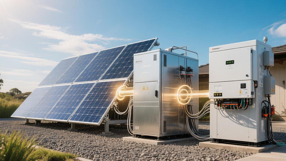
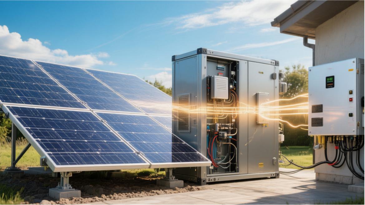
Solar cell energy storage systems, by converting direct current (DC) produced by solar panels into alternating current (AC), provide for home or business use. The inverter, after converting DC into AC, stores it in the cell. Batteries usually use lithium cell technology, efficiency as high as 90% or more, charge-discharge stability is good.
Conversion
Sunlight becomes DC
Roof-installed monocrystalline silicon modules usually are composed of 60 or 72 cell pieces connected in series, the open-circuit voltage of a single panel is approximately between 45 volts to 50 volts. When 10 pieces of 450-watt panels are connected in series to the inverter, the DC bus voltage will maintain at 350 volts to 450 volts, and the current intensity remains at about 10 amperes to 11 amperes.
In the process of light intensity increasing from 200 watts/square meter to 1000 watts/square meter, the MPPT (Maximum Power Point Tracking) controller every 1 second to 3 seconds adjusts the impedance once, ensuring conversion efficiency maintains above 99%. If encountering partial shadow occlusion, the output power of a single module might instantly drop from 400 watts to 100 watts, causing the voltage fluctuation range of the entire series circuit to reach more than 20%.
· A standard 10 kW array consists of 22 pieces of 450-watt panels, occupying about 45 square meters of roof area.
· DC cables adopt 4 square millimeter specifications, and the voltage loss within 50 meters length needs to be controlled within 1%.
· For every 5 degrees deviation in bracket tilt angle, the power generation fluctuation range in winter and summer seasons is about 3% to 5%.
· The waterproof level of the junction box needs to reach IP68, ensuring continuous work for 25 years in a 90% humidity environment.
Conversion efficiency is high
Hybrid inverters, when converting DC into AC, will produce about 2% to 4% energy loss; these losses mainly manifest as heat energy, making the temperature of the heat sink inside the chassis rise to 50 degrees Celsius. To improve efficiency, modern inverters adopt silicon carbide power devices, reducing switching loss by 30%, making the total heat dissipation power during full-load operation controlled within 150 watts.
When the energy storage system performs charge-discharge conversion, the bidirectional DC converter (DCDC) can make the 100-volt to 500-volt cell voltage accurately match the 400-volt DC bus voltage, its conversion error precision controlled within 0.1 volts. If the system detects that the inversion efficiency is lower than 90%, the built-in microprocessor will within 100 milliseconds issue an alarm and adjust the working frequency.
· For an inverter with a rated power of 5 kW, the efficiency at 25% load is usually about 2% lower than at full load.
· The fan speed of the air-cooling heat dissipation system automatically adjusts between 1500 rpm to 3000 rpm according to temperature.
· The design life of electrolytic capacitors is usually 100,000 hours, which is the main parameter limiting the 10-year warranty period of the inverter.
· The total harmonic distortion (THD) produced during the conversion process must be lower than 3%, to protect optical modems and precision audio equipment.
Current becomes AC
The output voltage is locked at 220 volts, the allowed dynamic deviation range is plus or minus 11 volts, and the frequency deviation needs to be controlled within plus or minus 0.2 Hertz. When the home's induction cooker (2000 watts) and microwave oven (1200 watts) start at the same time, the system output current will instantly soar from 5 amperes to 15 amperes, the waveform adjustment time is usually less than 20 milliseconds. This high-frequency conversion can keep the phase angle deviation of the AC within 1 degree, ensuring real-time synchronization with the national grid's electricity.
· The rated output current of a single-phase inverter is usually 21.7 amperes, and peak current can briefly reach 40 amperes.
· The crest factor of the pure sine wave needs to be maintained around 1.414, preventing motor equipment from heating up.
· Static power consumption (when not generating electricity at night) is usually limited to 5 watts to 10 watts, consuming about 60 kWh of electricity per year in vain.
· The weight of the internal inductor of the inverter accounts for 30% of the machine's weight, being the key physical module for filtering high-frequency noise.
Cell stores electricity amount
Energy storage cell packs usually consist of 16 pieces of 3.2-volt lithium iron phosphate cells connected in series to form a 51.2-volt module, or reach a 400-volt high-voltage system through multiple modules in series. When charging, the system will charge at a 0.5C rate (meaning a 5 kW system charges at 2.5 kW speed), which can guarantee the cell temperature rise does not exceed 8 degrees Celsius.
The usable Depth of Discharge (DoD) of the cell is generally set at 90%, a 10 kWh cell actually releases 9 kWh, reserving 10% to prevent the cell over-discharge from causing an internal resistance permanent increase of more than 15%. Each cell's voltage consistency deviation needs to be controlled within 20 millivolts, otherwise the BMS will start passive balancing, consuming the excess energy of high-voltage cells through resistors.
· A 10 kWh cell pack weighs about 120 kg, with external dimensions approximately 60 cm by 80 cm by 20 cm.
· The self-discharge rate of lithium iron phosphate cells is lower than 3% per month, even after being placed for half a year, there is still more than 80% of electricity.
· The internal resistance of a cell is usually between 0.5 milliohms and 2 milliohms, the heat production during charging and discharging is proportional to the square of the current.
· When the ambient temperature is lower than 0 degrees Celsius, the system will limit the charging current, preventing lithium dendrite growth from penetrating the separator.
Intelligently exchange energy
If solar output is 5 kW and home consumption is 2 kW, the remaining 3 kW will be charged into the cell with 96% charging efficiency. When the cell is full and the home load is low, the extra electricity will be fed back to the grid at a set power (such as 1 kW to 5 kW), exchanging for local electricity selling income of about 0.3 yuan to 1.0 yuan per kWh.
In the electricity price peak and valley periods, the system will automatically absorb 3 kWh from the grid for storage during the 2 AM low electricity price period, and release it during the 6 PM peak electricity use period. The arbitrage space for a single operation is about 0.5 yuan per kWh.
· The measurement accuracy of the current transformer (CT) is usually level 1, meaning the measurement error is within plus or minus 1%.
· The delay time for the system to respond to the turning on of high-power home appliances is usually between 150 milliseconds and 300 milliseconds.
· The mobile App data update frequency is usually once every 5 seconds, displaying voltage, current, and daily cumulative power generation.
· The cloud server will record the power generation curve of the past 365 days, used to predict the cell electricity retention strategy for the next 3 days.
Keep electricity stable
When the external power grid suffers a power outage due to failure, the energy storage system will within 10 milliseconds to 20 milliseconds automatically disconnect the grid-connected switch and transfer to off-grid operation mode. This switching speed is so fast that running computer hosts (usually having 16 milliseconds of capacitor maintenance time) will not shut down or restart.
In off-grid state, the inverter will simulate the grid to provide a 220-volt voltage reference, and possesses 2 times the rated power instantaneous starting ability, supporting the 30-ampere impact current produced by air conditioner compressors at the starting instant. To prevent overload, if the home total power continuously exceeds 5.5 kW for more than 30 seconds, the system will according to preset logic automatically cut off the power supply circuit of non-critical loads (such as water heaters).
· The maximum surge current capacity of the lightning protector is usually 40 kiloamperes, able to absorb instantaneous high voltage produced by induced lightning.
· If the insulation resistance monitoring function finds the DC side resistance to ground is lower than 100 kilohms, it will immediately cut off the DC input.
· The residual current device (RCD) trigger current is set at 30 milliamperes, preventing the risk of personnel electric shock.
· When the system runs above 2000 meters altitude, because the air is thin, the heat dissipation efficiency will drop by about 10%, requiring derated use.
Storage
What materials are used
The interior of a home energy storage system usually consists of dozens of square rectangular cells. The nominal voltage of this lithium iron phosphate cell is 3.2 volts, and capacity is usually between 100 Ah and 280 Ah. To reach the 48-volt or 51.2-volt rated working voltage, the system will connect 16 cells in series through red copper busbars with a thickness of 2 mm to 3 mm. This material's energy density is around 140 Wh/kg to 160 Wh/kg, for a standard 10 kWh cell pack, the net weight of cells alone reaches 65 kg to 75 kg, and the total weight after adding the metal shell and circuit board will exceed 110 kg.
Parameter Name | Typical Data Range | Remark Description |
Single Cell Voltage | 3.2V - 3.65V | Full charge voltage is 3.65 V |
Series Number | 16 groups or more | Determines total voltage of cell cluster |
Energy Density | 145 Wh/kg | Mainstream level of lithium iron phosphate |
Internal Resistance | < 0.5 milliohms | Lower represents smaller heat loss |
Shell Protection | IP65 | Allows installation in semi-open outdoors |
These cells are tightly arranged in a chassis made of 1.5 mm thick cold-rolled steel plate, and the interior will also be filled with thermal silicone sheets to assist heat dissipation. In the process of DC charging, charges move between positive and negative poles, the chemical energy conversion efficiency is between 95% to 98%, for every 10 kWh stored, about 0.2 kWh to 0.5 kWh will become heat and dissipate in the chassis.
If adopting a high-voltage storage solution, the system will connect hundreds of cells in series, making the voltage reach 350 volts to 450 volts, so that when transmitting the same power, the current can be reduced from 100 amperes to about 20 amperes; since heat loss is proportional to the square of the current, the high-voltage solution can reduce line loss by about 60% to 80%.
Steward ensures safety
The Cell Management System (BMS) is the intelligence center inside the storage box. It reads voltage, current, and temperature data from sensors everywhere more than 10 times per second. The BMS circuit board integrates dedicated analog front-end chips, the detection accuracy can reach 2 millivolts, which can ensure that any of the 16 series cells appearing to have voltage deviation can be found.
When a certain cell's voltage reaches the 3.6-volt warning line, the BMS will start the active balancing function, transferring excess energy to low-voltage cells through a small transformer with 2-ampere to 5-ampere current, or burning off the extra electricity through a resistor, ensuring the capacity pace of the entire cell group is consistent.
BMS Monitoring Item | Protection Trigger Threshold | System Action |
Overcharge Protection | 3.7V (Single) | Cut off charging relay |
Over-discharge Protection | 2.5V (Single) | Stop output to external |
Charge Temp Control | < 0°C or > 55°C | Limit current or disconnect |
Short Circuit Protection | > 300A (10ms) | Fuse blow or turn off MOS tube |
Communication frequency | 500 kbps | CAN bus real-time data exchange |
To prevent large current impacts, the BMS interior is configured with multiple sets of parallel power MOS tubes. These switch tubes can withstand instantaneous current impacts exceeding 500 amperes without damage.
If the home power load suddenly increases, for example, a water pump needing 10 kW power at the start instant, the BMS will allow the cell to output double current within 3 seconds to 5 seconds. Meanwhile, the system maintains a dialogue with the inverter through RS485 or CAN bus, sending a data packet every 50 milliseconds, synchronizing the current State of Charge (SOC) and State of Health (SOH), ensuring the inverter will not forcefully pull load when the cell is almost out of power.
Charge and discharge have loss
Energy is not completely lossless in the process of entering and exiting the cell, the industry usually uses Round-trip Efficiency to measure, mainstream lithium iron phosphate systems can achieve 90% to 94%. If solar produced 10 kWh DC electricity, stored in the cell through charging conversion, then converted into AC through discharge conversion for microwave oven use, in the end there might only be about 9 kWh left. The remaining 1 kWh is consumed in three places: first is cell internal resistance heating, accounting for about 4%; second is inverter conversion loss, accounting for about 3% to 5%; third is the operation power consumption of the BMS system and heat dissipation fans themselves, about 0.5 kWh per day.
To reduce these losses, it is suggested during installation that the connection cable length between cell and inverter be controlled within 2 meters, and the cable cross-sectional area be no less than 25 square millimeters. If using wires with insufficient thickness, when outputting 5000 watts of power, the voltage drop across both ends of the cable might reach 1 volt to 2 volts, this will cause an additional 1% to 2% of energy to become wire heat. In long-term operation, this energy loss will accumulate, calculated by 350 charge-discharge cycles per year, a 1% efficiency difference loses an extra 35 kWh of electricity annually, equivalent to an electricity bill of about 10 dollars to 20 dollars.
Can use for how many years
A high-quality lithium iron phosphate cell group, under 80% Depth of Discharge (DoD), can usually cycle 6000 times to 8000 times. If using up 80% of the cell and then fully charging every day, it can be used for 16 years to 22 years. By that time, the cell is not unusable, but the capacity will decay to about 80% of the initial state. Experimental data shows that the depth of discharge has a huge impact on life: if only 50% of electricity is used before charging each time, the cycle life can be extended to more than 12,000 times; but if electricity is often dried to 0%, the life might shrink to within 3000 times.
Depth of Discharge (DoD) | Estimated Cycle Times | Cell Service Total Energy (10kWh basis) |
100% | 2,500 times | 25,000 kWh |
80% | 6,000 times | 48,000 kWh |
50% | 12,000 times | 60,000 kWh |
30% | 20,000 times | 66,000 kWh |
The internal resistance of the cell will increase with use time, on average rising about 2% to 5% annually. When the internal resistance increases from the initial 20 milliohms to 40 milliohms, the heat production during charging and discharging will double, and the system for safety will automatically limit the maximum output power. To delay this aging, the BMS will set the charge cutoff voltage at 3.55 volts instead of the theoretical limit of 3.65 volts. This practice, although making usable capacity reduce by about 3%, can reduce lattice damage of the positive electrode material, elevating the calendar life from 10 years to over 15 years.
Afraid of cold and also afraid of heat
Temperature is the most sensitive external variable affecting energy storage system performance. The best working range for lithium iron phosphate batteries is 15 degrees Celsius to 35 degrees Celsius. When the ambient temperature drops below 0 degrees Celsius, the moving speed of lithium ions in the electrolyte slows down, the cell internal resistance will instantly surge by more than 50%, at this time, forced large current charging will cause lithium metal to precipitate on the negative electrode surface, causing permanent capacity damage or even puncturing the separator. Therefore, high-end storage chassis interiors will be attached with 100-watt power heating films, preheating first when detecting temperature lower than 5 degrees Celsius in cold regions, waiting for the cell temperature to rise before starting charging.
Ambient Temperature | Charge-Discharge Ability | Life Damage Situation |
-20°C | Only very small current discharge allowed | Cannot charge, forced charging means damage |
0°C | Charge power limited to 20% | Long-term operation easily produces dendrites |
25°C | 100% Full power operation | Best life performance |
45°C | Allows full power but aging accelerates | Decay rate 1.5 times faster than normal temperature |
60°C | Forced shutdown protection | Exists thermal runaway risk |
In hot summer, if the cell is installed on a closed wall without ventilation and with west sun exposure, the internal temperature might soar to 50 degrees Celsius. At this time, the BMS will forcibly enter derating mode, limiting the original 5 kW output power to 2 kW to reduce internal heat production. If the temperature continues to rise and touches the limit value of 60 degrees Celsius, the system will completely cut off the main relay to enter protection lock state.
To ensure safety, storage equipment usually requires installation at a position more than 10 cm above the ground to prevent water accumulation, and at least 20 cm of heat dissipation space must be reserved around it. This physical layout can let passive natural convection take away about 70% of the accumulated heat on the chassis surface.
Stability
Hold down voltage numbers
The Digital Signal Processor (DSP) inside the inverter samples and corrects the output waveform at a frequency of more than 20,000 times per second, controlling the 220-volt standard AC voltage deviation within plus or minus 2%.
Even during summer peak electricity use, when neighbors' air conditioners start in large batches, causing the external grid voltage to drop to 190 volts, the storage system's built-in voltage regulation compensation module will react within 15 milliseconds, forcefully pulling the output back to 220 volts through inductor coils and capacitor arrays. This high-precision control can let LED light bulbs avoid flickering that is undetectable by the human eye but will damage eyesight, while reducing the noise floor of high-end audio systems by more than 10 decibels.
In terms of voltage frequency, the system must strictly guard the 50 Hertz benchmark, its allowed error range is only plus or minus 0.1 Hertz. If the frequency deviation exceeds 0.5 Hertz, equipment like old-fashioned electronic clocks or washing machines with induction motors will experience running time deviation or abnormal motor heating, loss of power will consequently rise by about 15%.
Storage inverters through multi-stage LC filter circuits, filter out various high-frequency noises produced during the conversion process, keeping Total Harmonic Distortion (THD) below 3%. In contrast, modified sine waves produced by cheap off-grid inverters often have distortion rates as high as over 20%, which will cause the temperature of the electrolytic capacitor of laptop power adapters to rise by 10 degrees Celsius.
To maintain this output purity, the film capacitors inside the inverter need to withstand tens of thousands of charge-discharge impacts per second, their design voltage resistance is usually set above 1000 volts, ensuring stable working life of over 100,000 hours even when ambient temperature reaches 40 degrees Celsius.
Avoid surge impact
Storage systems arrange secondary Surge Protective Devices (SPD) on both AC and DC sides, the core of these modules is varistors, which can sense abnormal high voltage exceeding 400 volts within 0.000001 seconds and discharge excess energy to the ground wire.
In thunder and rain weather, even if nearby induced lightning produces instantaneous high voltage as high as 4000 volts, the protector can also through physical fusing or fast discharging limit the residual voltage entering the house to below 1500 volts, this value is within the safety range of home appliance insulation voltage resistance. The internal electrical isolation design of the system can withstand 5000-volt DC voltage resistance tests, completely cutting off the physical path for DC side high voltage to accidentally leak into the AC side.
Safety protection is not only for the grid, but also for personal safety. The built-in Residual Current Monitoring Unit (RCMU) of the system has a detection accuracy for leakage current of 1 milliampere, once finding leakage exceeding 30 milliamperes, the leakage protection device will act within 0.02 seconds, more than 5 times faster than ordinary air switches.
Taking a system with 5 kW rated power as an example, it usually allows outputting 2 times the rated power (i.e., 10 kW) within 10 seconds, to deal with the 5 to 7 times starting current produced at the starting instant of air conditioner compressors or high-power water pumps. If there is no such instantaneous support capability, the system will undergo protective shutdown at the moment large appliances are turned on because of the sudden voltage drop.
Modern systems, by monitoring the current growth slope, can predict the load type, and within 0.1 seconds adjust the conduction duty cycle of the IGBT module, ensuring the voltage drop range does not exceed 10% of the nominal value, thereby protecting running computers from blue screening due to unstable voltage.
Switching has no movement
High-end storage systems adopt seamless switching technology, switching time is usually suppressed within 10 milliseconds to 20 milliseconds. According to electronic industry standards, the internal storage capacitors of most desktop computer and game console power supplies can support about 16 milliseconds of power outage without shutting down, as long as the switching speed is fast enough, users will not even feel light flickering during power outages, and ongoing network meetings will not drop. This fast response relies on built-in high-speed relays and prediction algorithms. The system will continuously monitor the grid waveform, starting to prepare to disconnect the grid connection at the 3rd cycle of finding waveform distortion.
Stability under off-grid mode completely depends on the cell's instantaneous output capability. A set of 48-volt 200-Ah cell group, when outputting 5 kW power off-grid, the discharge current will reach more than 100 amperes. At this time, the internal resistance of wires and connectors must be controlled below 0.5 milliohms, otherwise the heat produced just at the joint is enough to melt the plastic shell.
Anti-islanding Protection Devices (AFD) will inject tiny frequency disturbance signals into the grid, once finding the grid impedance has abnormal changes, it will within 0.2 seconds forcefully cut off the connection with the outside. In off-grid state, the inverter will change from "following the grid" to "setting benchmark by itself", utilizing built-in high-precision crystal oscillators to produce a stable 50 Hertz frequency.
At this time, the system will according to the cell State of Charge (SOC) calculate the supportable time in real-time. If electricity is lower than 5%, it will automatically cut off power supply to unimportant sockets, prioritizing loads like lighting and refrigerators that maintain 24-hour operation.
Heat dissipation controls aging
The stability of electronic equipment is inversely proportional to temperature. For every 10 degrees Celsius increase in the temperature of internal power semiconductor devices (such as MOSFET or IGBT), their expected failure rate will double. Storage systems, through smart air cooling or advanced natural convection heat dissipation design, control the internal maximum temperature during full-load work within 65 degrees Celsius.
Sensors at the bottom of the system read temperature data from 3 key locations every second. When the heat sink temperature reaches 45 degrees Celsius, brushless DC fans will start at 1500 rpm; if the temperature rises to 55 degrees Celsius, fan speed will linearly increase to 3500 rpm, noise level can still be maintained below 45 decibels, equivalent to the background sound of a quiet library.
Long-term operation stability is also reflected in tolerance to the environment. IP65 level protection equipment can block water flushing at a flow rate of 100 liters per minute without leaking, this guarantees that during the plum rain season in the south where humidity exceeds 90%, the circuit board will not suffer high-voltage arcing failure due to condensation.
The Printed Circuit Board (PCB) inside the inverter is usually sprayed with conformal coating (moisture-proof, salt spray-proof, mold-proof), the thickness accurately controlled at 0.05 mm. Heavy modules like inductors and transformers adopt high-strength structural adhesive for reinforcement, preventing solder joints from cracking due to resonance during long-distance transportation or operation.
In extreme high-temperature dry regions, if the ambient temperature continuously exceeds 50 degrees Celsius, the system will automatically start the derating operation strategy, limiting output power to about 60% of the rated value, through actively sacrificing part of the power supply capability to exchange for core hardware not being burned out.