How to Install Monocrystalline Solar Panels | 3 Steps
Installing monocrystalline solar panels with a conversion rate typically as high as 20%-22% requires a core process of just three key steps.
The first is basic installation: aluminum alloy guide rails must be firmly installed on a roof with a load-bearing capacity that meets standards (south-facing and a tilt of about 30 degrees is recommended to maximize light capture), and waterproofing must be applied to the drilled holes.
Second is Fixing the Panels: the monocrystalline modules are secured onto the rails using windproof clamps, with a gap of approximately 2 cm reserved between panels to account for thermal expansion and contraction.
Finally, there is the electrical connection: the wiring is standardized and connected to the inverter (such as a common 5 kW home system);
For safety and compliance reasons, this grid-tied testing step must be completed by a licensed professional electrician to ensure the system generates power stably and efficiently.
Install the Mounting System
Locate the Wooden Beams
When constructing a standard wood-structure asphalt shingle roof, an electronic detector set to a frequency of 50 Hz is required to scan for the standard 2x4 specification wooden rafters underneath, which have a width of 38 mm and a thickness of 89 mm.
The center-to-center spacing between two adjacent load-bearing wooden rafters is typically 406 mm (16 inches) or 610 mm (24 inches), and the error range for construction markings must be strictly controlled within plus or minus 5 mm.
Pull a 15-meter long, 1-mm diameter nylon chalk line across the roof surface, tensioned with a force of 30 N to snap a straight baseline, ensuring that the horizontal height variance over an 8-meter long row of brackets does not exceed 2 mm.
The vertical distance from the first row of bracket bases to the edge of the eaves must be maintained between 300 mm and 400 mm, which reserves a rainwater runoff space of 0.5 liters per second for a roof with a 20-degree tilt.
The span between the upper and lower rows of brackets is strictly set between 1,100 mm and 1,200 mm, based on the physical length of 1909 mm of a single 450W monocrystalline panel, to form a support surface capable of withstanding a snow load pressure of 2400 Pa per square meter.
Drilling and Waterproofing
Use a drill equipped with a high-speed steel bit of 8 mm in diameter and a hardness reaching HRC60 to drill a pilot hole with a depth of 65 mm at a perfect 90-degree angle perpendicular to the roof surface.
· Within 5 seconds after drilling each hole, an air gun must be used to blow away over 95% of the sawdust and dust inside the hole to ensure that the adhesion of the subsequent sealant reaches a maximum value of 100%.
· Continuously and evenly squeeze approximately 15 ml to 20 ml of outdoor-grade polyurethane waterproof silicone, with a temperature resistance range of minus 40 degrees Celsius to 90 degrees Celsius, into each 65 mm deep hole and within a 50 mm radius circle around it.
· Within 10 minutes before the silicone surface dries, quickly slide in a 200 mm by 300 mm, 0.5 mm thick aluminum oxide waterproof gasket (Flashing), tucking the upper 100 mm portion deep under the layer of asphalt shingles above.
· The 8 mm center opening of the gasket must achieve 100% concentric alignment with the 65 mm deep hole in the roof; the positional deviation rate must not exceed 1%, otherwise there is a 0.5% probability of water seepage in regions with annual precipitation exceeding 800 mm over 10 consecutive years.
Fixing the Bases
Place the 85 mm high L-shaped aluminum alloy base directly on top of the 0.5 mm thick waterproof gasket, and insert a stainless steel hex lag bolt with a diameter of 8 mm and a length of 75 mm (the specification is usually 5/16 x 3 inches).
Use an 18-volt lithium electric wrench with a 13 mm socket to drive this 75 mm long bolt into the underlying wooden rafter at a low speed of 300 RPM.
The final three turns of tightening must be switched to a manual torque wrench with a scale accuracy of 0.1 Nm, with the tightening torque set precisely between 14 Nm and 16 Nm to prevent excessive compression from causing hidden cracks wider than 1 mm in the wood.
An L-shaped base installed according to this 15 Nm torque standard can withstand an upward pull-out force of over 450 kg in the vertical direction, enough to handle Level 15 short-term gusts with wind speeds reaching 180 km/h.
Based on a density distribution of installing one base every 1.2-meter span, a 5 kW system consisting of 12 panels requires fixing approximately 30 to 34 such high-strength load-bearing bases on the roof.
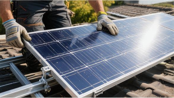
Mount the Monocrystalline Panels
Moving Onto the Roof
Two construction workers, wearing full-body five-point safety harnesses with a tensile strength of 22 kN, need to move the single monocrystalline silicon panels—measuring 1909 mm long, 1042 mm wide, and 35 mm thick—steadily up an aluminum alloy extension ladder at a tilt of 25 degrees.
The net weight of this 450W panel, composed of 144 half-cut monocrystalline silicon cells connected in series, is 23.5 kg. When carrying it, both hands must firmly grip the aluminum alloy frame of the long side at the optimal weight-bearing points located 400 mm from each end.
Although the static pressure limit of the tempered glass on the front of the panel is as high as 5400 Pa, an accidental corner impact on the ground caused by a tilt angle exceeding 15 degrees during handling will generate an instantaneous concentrated impact force exceeding 800 N. This will cause the 3.2 mm thick low-iron, high-transmittance tempered glass surface to burst with reticulated cracks longer than 50 mm.
Upon reaching the roof work surface 4.5 meters above the ground, place the panels face down on four 15 mm thick EPE pearl cotton spacer blocks. Each block must have a contact area of 200 mm by 200 mm to prevent asphalt shingle granules with a surface roughness of 2 mm from scratching the 0.3 mm thick fluorine film insulation and moisture barrier on the backsheet.
Plugging in Connectors
Before the monocrystalline panels are completely flipped and fixed to the rails, the two built-in DC photovoltaic cables on the back, each 1200 mm long and with a cross-sectional area of 4 square mm, must be addressed first.
Insert the positive and negative MC4 waterproof connector terminals horizontally into each other, applying about 60 N of axial pushing force until a mechanical locking "click" is heard at a volume of approximately 45 dB.
Once fully locked, the connector's dust and water resistance immediately reaches the IP68 level, allowing it to be continuously immersed in water 1 meter deep for 24 hours while maintaining zero leakage.
Next, use UV-resistant black nylon cable ties with a width of 4.8 mm and a tensile strength of 22 kg to bundle the excess hanging cables every 300 mm inside the 15 mm deep grooves under the aluminum alloy guide rails.
The lowest U-shaped point of the bundled cables must maintain a vertical clearance of at least 50 mm from the asphalt roof to prevent the surface temperature of the roof—which can reach 70 degrees Celsius at summer noon—from accelerating the thermal aging rate of the cross-linked polyethylene material on the cable jacket, which would significantly shorten its original 25-year design life by 30%.
The bending radius at all cable turns must absolutely not be less than 4 times the cable's outer diameter, meaning a minimum arc radius of 24 mm must be maintained; otherwise, it will cause microscopic metal fatigue failure in more than 5% of the 56 tinned pure copper wires with a diameter of 0.3 mm inside the cable.
Alignment and Gapping
The first 450W monocrystalline panel must be placed exactly 50 mm from the leftmost edge of the bottom guide rail, with a parallelism error between the long-side frame and the 8.4-meter long horizontal rail within a range of plus or minus 2 mm.
When the two workers together lay the second adjacent panel flat, two rigid plastic positioning blocks with a thickness of exactly 20 mm must be forcibly inserted between the aluminum frames of the two panels.
This 20 mm physical gap is used to absorb and digest the thermal expansion and contraction deformation of the aluminum alloy material caused by the local extreme temperature difference of up to 60 degrees Celsius between winter and summer. If the installation gap is forced to be less than 10 mm, thermal expansion stress will break through 70 N per square mm when outdoor temperatures reach 40 degrees Celsius in summer, causing the panel frames to bend upward by 2 to 3 degrees.
The height difference between the two panels along the 1909 mm long side needs to be measured with a 300 mm industrial-grade steel ruler; the difference must be strictly controlled within a tolerance range of 1.5 mm.
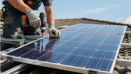
Tightening Screws
At the outermost rail position of the first panel, snap in a 40 mm long aluminum alloy end clamp with a height of 35 mm that perfectly matches the panel's thickness.
Insert an M8 diameter, 40 mm long stainless steel hex socket screw and use an 18-volt lithium cell electric wrench with an 8 mm hex bit to pre-tighten it at a low speed of 200 RPM to an initial torque of 5 Nm.
In the dead center of the 20 mm wide gap between the two panels, snap in a T-shaped mid clamp with a top flange width of 24 mm, ensuring it covers a 12 mm wide edge frame of the panel glass on both the left and right sides.
Clamp Type | Coverage Width | Screw Specification | Standard Torque | Applicable Gap |
End Clamp | 40 mm | M8 × 40 mm | 15 Nm | 0 mm (Edge) |
Mid Clamp | 24 mm | M8 × 40 mm | 15 Nm | 20 mm |
Grounding Lug | 35 mm | / | 15 Nm | 0.1 mm |
Pre-tighten the M8 screws of the mid clamps to 5 Nm using the electric wrench, then repeat this mechanical action of placing clamps until all 10 mid clamps and 4 end clamps required for an array consisting of one row of 6 panels are in place.
Switch to a manual torque wrench with a scale accuracy of 0.5 Nm. Following a load sequence extending from the center (3rd and 4th panels) toward both the left and right sides simultaneously, tighten all 14 M8 screws to the standard torque range of 14 Nm to 16 Nm.
After applying the standard torque of 15 Nm, the toothed stainless steel washer at the bottom of the mid clamp will pierce downward through the 15-micron thick anodized layer on the rail surface with a pressure of 80 MPa, reaching a piercing depth of 0.5 mm and a contact area of 80 square mm. This establishes an equipment equipotential grounding network with a resistance of less than 0.1 ohms at the physical level.
Wiring and Inverter Connection
Conduit Pipe
Insert the positive and negative photovoltaic DC cables with a cross-sectional area of 4 square mm into a UV-resistant rigid PVC flame-retardant conduit with an outer diameter of 25 mm and a wall thickness of 2 mm.
After two 6-mm outer diameter cables are pulled into the pipe, the cross-sectional space filling rate inside the conduit is maintained at exactly 18%, far below the 40% maximum limit required by electrical codes. This allows the cables to maintain a natural convection heat dissipation efficiency of 0.5 cubic meters per minute in a high-temperature environment of 65 degrees Celsius.
Along a 15-meter long brick exterior wall, construction workers need to install a metal pipe strap capable of bearing 10 kg every 1.5 meters, using galvanized expansion screws with a diameter of 6 mm and a length of 40 mm.
When turning at a 90-degree corner, a wide-radius prefabricated elbow with a bending radius of 150 mm must be used to ensure the tensile deformation rate of the 56 tinned copper wires with a diameter of 0.3 mm inside the cable remains below 0.5% during the pulling process.
For PVC conduit laid in outdoor environments for up to 20 years, the material formula needs to contain 3% titanium dioxide to increase the absorption rate of ultraviolet light with wavelengths between 280 nm and 400 nm to 99%, preventing the conduit from becoming brittle with a hardness decrease of more than 20% after 10,000 hours of sunlight exposure.
Stripping Wire Ends
Construction workers use professional photovoltaic wire strippers matching the US wire gauge AWG 12 to precisely strip the red and black PV1-F double-insulated cable jackets. The exposed multi-strand copper core length must be strictly controlled within the range of 7 mm to 9 mm.
The closing gap of the wire stripping blade is factory-preset at 2.2 mm, which happens to cut through the 1.8 mm thick cross-linked polyethylene outer jacket and the internal insulation layer while maintaining a safety distance of 0.1 mm from the internal copper core conductor with a diameter of 2.4 mm.
If excessive force is used during stripping, resulting in the cutting of more than two thin copper wires with a diameter of 0.3 mm, the current-carrying capacity of the entire cable at that section will instantly drop by 3.5%. When passing a rated DC current of 13 Amps, the temperature at the contact point will soar to over 85 degrees Celsius within 30 minutes.
After stripping the 8-mm long intact copper core, the MC4 metal inner core made of tinned pure copper must be quickly fitted over it within the next 120 seconds to prevent the pure copper surface exposed to air with 60% humidity from oxidizing within 5 minutes into a copper oxide film with a thickness of 0.05 microns and extremely low conductivity.
Crimping Terminals
Place the MC4 metal male and female terminals fitted with the 8-mm copper core into the 2.5 square mm to 4 square mm slot of a professional photovoltaic crimping tool with a ratchet self-locking mechanism, and apply approximately 250 N of gripping force with both hands.
As the crimping tool handle emits three crisp gear-ratchet advancement sounds, the jaws wrap the 0.5-mm thick tinned copper sheet tightly around the 56 thin copper wires with a pressure of 20 MPa, forming a hexagonal dense cold-pressed junction with a cross-sectional area of 3.8 square mm.
The crimped terminals need to undergo a destructive random inspection by a tensile tester. A qualified crimp terminal must withstand 400 N of axial pull-out force for 60 seconds without the wire core slipping more than 0.5 mm.
Push the crimped metal terminals into the PC material plastic shell with a flame-retardant rating of UL94-V0. When the insertion distance reaches 15 mm, it will trigger the metal snap spring to pop out. The anti-pull-out locking design can withstand up to 50 kg of reverse pull, permanently locking the contact resistance after the positive and negative plugs are joined to below 0.3 milliohms, ensuring that the voltage drop during 500-volt DC transmission is less than 0.1%.
Mounting the Inverter
On an indoor load-bearing brick wall at a vertical height of 1.5 meters from the ground, plan a dedicated equipment installation zone with a width of 800 mm and a height of 1,200 mm.
In the exact center of this area, use four stainless steel metal expansion bolts with a diameter of 8 mm and a length of 60 mm to fix a 1.5-kg aluminum alloy mounting plate to the wall. Each bolt requires 12 Nm of tightening torque applied with a socket wrench.
The combined shear resistance generated by the four expansion bolts reaches 400 kg, firmly holding a single-phase grid-tied inverter with a net weight of 15 kg and a rated output AC power of 5,000 Watts.
After the inverter is hung, a blank distance of 300 mm must be left on both the left and right sides of the machine, and a cooling space of 500 mm must be reserved at the top and bottom of the machine.
When a single 5 kW inverter is running at full load in an environment where the summer room temperature reaches 35 degrees Celsius, the temperature of the aluminum cooling fins on the back of the machine will reach 65 degrees Celsius. The ample 500 mm top and bottom ventilation distance allows 1.2 cubic meters of hot air to be discharged smoothly per minute through natural convection, keeping the operating temperature of the IGBT modules inside the machine within the safety red line of 85 degrees Celsius.