What are the Solar Panels and Comparison | 3 Main Types
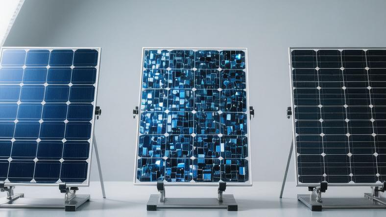
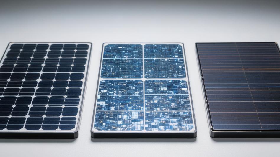
First is monocrystalline panels, which have the highest photoelectric conversion rate (about 20%-22%) and a lifespan that usually exceeds 25 years. Although the initial investment is the largest, they are most suitable for residential roofs with limited area;
Second is Polycrystalline panels, with a moderate conversion rate (about 15%-17%) and lower manufacturing costs, making them an excellent cost-effective choice for users with limited budgets;
Finally, there are Thin-Film panels, which have the lowest conversion rate (10%-13%), but excel in being lightweight, flexible, and having good low-light performance, making them very suitable for RVs, yachts, or large commercial roofs with load-bearing restrictions.
Monocrystalline Solar Panels
Manufacturing Process
The raw material for monocrystalline silicon panels is polysilicon feedstock with a purity reaching 99.9999% (6N) to 99.9999999% (9N), extracted from quartz sand.
Engineers melt the high-purity silicon in a quartz crucible at a high temperature of 1425°C, insert a single crystal seed, and spend 48 to 72 hours slowly pulling it upward to grow a cylindrical monocrystalline silicon ingot with a diameter typically of 200 mm or 300 mm.
The weight of this silicon ingot is between 150 and 300 kg.
After cooling, the factory uses diamond wire to cut the silicon ingot into wafers with a thickness of only 130 to 150 microns.
The cutting process results in a material loss of about 10% to 15%.
Wafers cut from the cylindrical ingot have chamfers on the four corners, resulting in small white diamond-shaped gaps at the junctions where the solar cells are assembled in the panel.
Currently, the mass-produced monocrystalline photovoltaic modules on the market are mainly divided into three technical routes, with performance parameters emphasizing different strengths:
· The mass-produced photoelectric conversion rate of PERC modules fluctuates in the range of 22.5% to 23.5%.
· TOPCon modules add an ultra-thin silicon oxide tunneling layer of 1 to 2 nm and a doped polysilicon layer to the back of the wafer, increasing the conversion rate to 24% to 25.2%.
· HJT (Heterojunction) modules deposit 5 to 10 nm of intrinsic amorphous silicon layers on both sides, maintaining an average conversion rate of around 25% on the production line, with the highest laboratory conversion rate reaching 26.8%.
Deconstructing the Parameter Sheet
Take an all-black module with an area of about 1.95 square meters and a nominal power of 400W for a specific deconstruction.
Under Standard Test Conditions (STC) of 1,000 W/m² solar irradiance and a 25°C cell temperature, a single module includes the following specific operating values:
· The Open Circuit Voltage (Voc) value marked on the parameter sheet is approximately 37.1 V, and the Short Circuit Current (Isc) is 13.5 A.
· When the panel is actually connected to an inverter for operation, the Maximum Power Point Voltage (Vmp) stays at 31.0V, and the Maximum Power Point Current (Imp) output is 12.91A.
· The interior of the panel usually contains 108, 120, or 144 half-cut cells connected in series.
Half-cut technology refers to using a laser to split a complete cell into two, halving the current passing through the interior and reducing internal resistance loss by about 75%, thereby increasing the output power of the entire panel by 5W to 15W without increasing the area.
Heat and Shadow Sensitivity
Monocrystalline silicon modules are very sensitive to ambient temperature; their working efficiency decreases as temperature rises.
The Maximum Power Temperature Coefficient (Pmax) on the parameter sheet is usually marked as -0.35%/°C.
When the actual temperature on a summer roof reaches 65°C, it is 40°C higher than the standard test temperature of 25°C.
At this time, the power attenuation calculation is 40 multiplied by 0.35%, resulting in a 14% power drop.
A 400W panel can actually output a maximum of only 344W at this time.
Shadow occlusion causes a cliff-like drop in power; if a leaf covers 10% of the area of a single cell, the output power of the entire panel will immediately drop by 33%.
Manufacturers pre-install 3 bypass diodes in the junction box on the back as a response mechanism.
Taking a panel with 60 complete cells inside as an example, every 20 cells are connected in series into a group, managed by one diode.
When one cell in a group is completely blocked by bird droppings, the diode will cut off the circuit for the corresponding 20 cells, allowing the current to pass through the bypass, leaving the overall panel output at 66% of its rated power.
Polycrystalline Solar Panels
Casting Process
The raw material for polycrystalline silicon panels is still high-purity polysilicon blocks.
Factories pour silicon fragments of various sizes into a square quartz crucible and heat it to 1500°C to melt it completely.
The inner wall of the crucible is coated with a layer of high-purity silicon nitride to prevent impurities from penetrating into the liquid silicon.
The liquid silicon cools naturally in a large square mold for 20 to 30 hours.
Unlike the slow pulling of a single cylindrical ingot in monocrystalline silicon, the cooling process of polycrystalline silicon simultaneously forms multiple small crystal grains.
The yield rate for ingot casting across the production line remains in the range of 95% to 97%.
After cooling and forming, square silicon ingots typically weigh between 400 and 500 kg.
Engineers use steel wire coated with diamond to cut the rectangular silicon ingot into square wafers with a thickness of 160 to 180 microns.
Since chamfering is not required, polycrystalline wafers present perfect square edges, with a standard side length of 156.75 mm.
During later assembly, the cells are fitted very closely together without any blank gaps.
The material loss rate for each wafer during the cutting and cleaning process stays at around 15%.
Blue Grain Boundaries
Light hitting irregular crystal boundaries undergoes diffuse reflection, and the surface is covered with a silicon nitride anti-reflective coating with a thickness of approximately 70 to 90 nm.
The overall appearance of the panel is deep blue or bright blue, and panels from different batches can have noticeable color differences.
For a standard 60-cell series module, the physical length and width dimensions are usually 1650 mm by 992 mm.
The frame thickness is set between 35 mm and 40 mm, manufactured using anodized aluminum alloy to resist outdoor rainwater corrosion.
The bottom of the frame has 4 to 8 elliptical mounting holes with a diameter of 9 mm reserved; workers use M8 specification stainless steel bolts to fix the panel onto aluminum alloy rails.
The net weight of the entire panel is maintained in the range of 18.5 kg to 19.5 kg.
The front is covered with a 3.2 mm thick low-iron, high-transmittance tempered glass.
Through wind tunnel testing, finished panels that pass factory inspection can withstand a static snow load of 5400 Pa (Pascal) on the front and a wind load test of 2400 Pa on the back.
Measuring Power Generation
Under standard test conditions of 1,000 W/m² irradiance and 25°C cell temperature, the photoelectric conversion efficiency of polycrystalline modules falls in the range of 15% to 18.5%.
Take a standard-sized polycrystalline panel with a nominal power of 280W to check the factory parameter sheet.
The Open Circuit Voltage (Voc) value on the sheet is calibrated at around 38.2V.
Short Circuit Current (Isc) data is typically measured at 9.5A.
After connecting to a home inverter and integrating into the grid for operation, its Maximum Power Point Voltage (Vmp) is maintained at 31.6 V.
The Maximum Power Point Current (Imp) stays at an output level of 8.86A.
The black plastic junction box on the back of the module is pre-installed with 3 bypass diodes.
The voltage endurance value of the bypass diodes is usually set at 45V, with a forward working current of 15A.
When partial snow accumulation blocks 20 cells, the diode activates to short-circuit the affected one-third area, allowing the entire panel to continue outputting the remaining 186W of available power.
In low-light environments, such as 7 AM or 6 PM, when solar radiation drops to 200 W/m², the panel can only output 15% to 18% of its rated power.
Thin-Film Solar Panels
Flexible Type
Flexible thin-film panels discard the heavy 35 mm aluminum alloy frame and the 3.2 mm explosion-proof tempered glass shell.
Its overall net weight is extremely compressed to a range of only 2.5 kg to 3 kg per square meter.
A flexible panel with a nominal power of 100 W, a length of 1,200 mm, and a width of 540 mm usually has a weight measured at around 1.8 kg.
Its physical structure allows for a maximum bending deformation of 30 to 45 degrees, which can perfectly fit curved roofs or metal hatches with a curvature radius of 0.3 to 0.5 meters.
Fatigue mechanical testing before leaving the factory requires the panel to undergo 5000 continuous bending cycles on a dedicated reciprocating bending tester at a frequency of 60 times per minute. The power output degradation rate after the test is strictly limited to within 3%.
Installation workers do not need to drill 10 mm expansion screw holes in color steel tiles.
They only need to peel off the industrial-grade double-sided tape (such as 3M's VHB tape series) on the back of the panel and apply a pressing pressure of about 15 psi to a dry metal or glass surface where the ambient temperature is higher than 15°C to complete the fixation.
Two skilled workers can complete the laying of 150 to 200 square meters of flexible panel arrays within the 8 effective working hours of a day.
Lower Conversion Rate
Under standard test conditions of 1,000 W/m² irradiance and 25°C cell temperature, the photoelectric conversion efficiency of mainstream commercial Cadmium Telluride (CdTe) thin-film modules falls in the range of 17% to 19.2%.
Copper Indium Gallium Selenide (CIGS) flexible panels typically fluctuate in a conversion rate range of 15% to 17%.
Amorphous Silicon (a-Si) materials have the lowest conversion efficiency, staying at a level of only 7% to 9%.
Take a CIGS flexible panel with a nominal output power of 100 W to check its laboratory parameter sheet.
The Open Circuit Voltage (Voc) value marked on the sheet is set at around 23.5 V. The Short Circuit Current (Isc) test data typically stays at 5.8 A.
After operating with a vehicle or marine MPPT solar controller, the Maximum Power Point Voltage (Vmp) remains at an output status of 19.2V.
The Maximum Power Point Current (Imp) is stable at a load level of 5.21A.
To build a 1.2 kW independent off-grid power generation system on an RV roof, using thin-film panels with a 16% conversion rate, would occupy about 7.5 square meters of available roof area.
Compared to using monocrystalline silicon rigid panels with a 22% conversion rate, the thin-film system occupies about 2.5 square meters more physical space.
The panel surface has no reflective metal grid lines, and the reflectivity is lower than 5%, making it extremely suitable for installation on height-restricted building roofs within 3,000 meters of airport runways.
Power Generation in Low Light
Thin-film solar panels show extremely strong resistance to high-temperature environments, with the factory-calibrated Maximum Power Temperature Coefficient (Pmax) usually set in an excellent range of -0.2% to -0.25%/°C.
When summer temperatures in North American desert regions reach 40°C, the actual working temperature of the panel attached to a dark metal vehicle roof will soar to 75°C.
This is a full 50°C above the standard test temperature of 25°C. 50 multiplied by 0.25% gives an instantaneous power drop of only 12.5%.
A 100W thin-film panel can still output 87.5W of actual power under 75°C of baking.
At 6:30 AM or 5:30 PM, when solar radiation intensity drops to a trough range of 150 W/m² to 200 W/m², thin-film panels wake up and start approximately 15 to 20 minutes faster than crystalline silicon panels.
Due to the use of an internal long-strip laser-scribed series structure, when a branch shadow 50 mm wide horizontally blocks 10% of the panel area, the output power of the entire thin-film panel only drops linearly by 10% to 12%. In contrast, when monocrystalline silicon panels suffer the same form of partial occlusion, the power drop is often as high as 33%.