Are solar cells connected in series or parallel
Solar cells are often connected in series to increase voltage (e.g., 36 cells for ~18V) or in parallel to boost current. Series connections are common in panels, while parallel wiring is used in arrays to maintain voltage while adding power capacity.
How Solar Cells Work
Solar cells, also called photovoltaic (PV) cells, convert sunlight directly into electricity. A typical silicon-based solar cell generates 0.5 to 0.6 volts under full sunlight, but the actual output depends on factors like cell efficiency (15-22% for most commercial panels) and sunlight intensity. For example, a standard 60-cell solar panel produces 250-400 watts at peak conditions, with each cell contributing roughly 5-6.5 watts.
The key to solar cell operation is the PN junction—a layer of silicon doped with phosphorus (negative side) and boron (positive side). When sunlight hits the cell, photons with energy above 1.1 electron volts (for silicon) knock electrons loose, creating a flow of electricity. About 20% of incoming solar energy gets converted into usable electricity in modern panels, while the rest is lost as heat or reflection.
"A single 100-watt solar panel exposed to 5 peak sun hours per day can generate 1.8 kWh per month per watt—enough to power small appliances like a laptop (50W) for 36 hours."
Solar cells degrade over time, losing 0.5-1% efficiency per year. Most manufacturers guarantee 80% output after 25 years. Temperature also affects performance: for every 1°C above 25°C, efficiency drops by 0.3-0.5%. That’s why panels in hot climates often produce 5-10% less power than rated capacity.
Thin-film solar cells, an alternative to silicon, are less efficient (10-13%) but cheaper to produce, costing 0.50−1 per watt compared to 0.70−1.20 for silicon panels. However, they degrade faster—losing 1-2% efficiency annually—making them less ideal for long-term installations.
Series vs Parallel Basics
When wiring solar panels, you have two main options: series or parallel connections. The choice impacts voltage, current, and overall system performance. A typical 60-cell solar panel outputs 30-40 volts and 8-10 amps at maximum power (around 300-400W). How you connect multiple panels determines whether those numbers add up or stay the same.
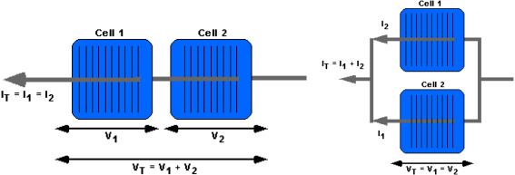
In a series connection, the positive (+) terminal of one panel links to the negative (-) of the next, increasing total voltage while keeping current (amps) constant. For example, wiring two 36V, 10A panels in series gives 72V at 10A—doubling voltage but maintaining the same current. This setup is ideal for long-distance wiring because higher voltage reduces power loss (P = I²R). A 100-foot 10-gauge wire carrying 10A at 120V loses 3.2% power, but at 240V, losses drop to 0.8%.
Parallel connections, on the other hand, combine positive-to-positive and negative-to-negative terminals, keeping voltage steady while adding current. Two 36V, 10A panels in parallel produce 36V at 20A—same voltage, double the current. This is useful when shading or panel mismatch is a concern since parallel wiring minimizes performance drops. If one panel in a series string drops 50% output, the whole string suffers. But in parallel, only the affected panel loses efficiency.
Connection Type | Voltage Change | Current Change | Best Use Case | Power Loss Over 100ft (10AWG) |
Series | Adds up (e.g., 36V + 36V = 72V) | Stays same (e.g., 10A) | Long-distance runs, high-voltage inverters | 0.8% at 240V |
Parallel | Stays same (e.g., 36V) | Adds up (e.g., 10A + 10A = 20A) | Shaded areas, mismatched panels | 3.2% at 120V |
Microinverters and optimizers change the game. With microinverters (one per panel), each unit operates independently at 240V AC, eliminating series/parallel tradeoffs. But they cost 100−150 per panel, adding 20-30% to system costs versus a central inverter (0.20−0.40 per watt).
MPPT charge controllers work best with higher voltage inputs (series), extracting 15-30% more power than PWM controllers in cold weather. A 48V cell bank fed by a 72V series array loses 5-8% conversion energy, while a 36V parallel array loses 10-12% due to lower input voltage.
Shading impacts series strings hard. If 25% of one panel is shaded, a series-connected system can lose 50-75% power, whereas parallel only drops 25%. That’s why rooftop systems with chimneys or trees often use parallel or microinverters.
Maximum system voltage also matters. Most residential inverters cap at 600V, meaning you can connect 15-18 panels in series (36V x 18 = 648V exceeds limits). Parallel setups avoid this but need thicker wires (lower gauge) to handle higher current. A 20A parallel array requires 10AWG wire, while a 10A series array can use 12AWG, cutting wire costs by 15-20%.
Series Connection Details
Wiring solar panels in series is the go-to method for maximizing voltage while keeping current flow steady. A typical residential solar panel operates at around 30-40 volts and 8-10 amps. When you connect two of these panels in series, the voltage stacks up (60-80V), but the current stays at 8-10A. This setup is ideal for systems using high-voltage string inverters (300-600V input) or MPPT charge controllers, which work 15-30% more efficiently at higher voltages.
Key advantages of series connections:
· Lower wire costs: Higher voltage means lower current for the same power, allowing thinner (cheaper) wires. A 10A series system can use 12AWG wire, saving 0.50−1 per foot compared to the 10AWG needed for a 20A parallel system.
· Reduced power loss: Power loss in wires follows P = I²R. At 10A, a 100-foot 12AWG wire loses 6.4 watts, but at 5A, losses drop to 1.6 watts—a 75% reduction.
· Better MPPT efficiency: Most MPPT controllers need at least 5V above cell voltage to start charging. A 48V cell requires 53V+ input, easily achieved with just 2 panels in series (60-80V).
However, series connections have critical limitations:
· Shading vulnerability: If one panel in a series string is 50% shaded, the entire string’s output can drop 50-75% because current must flow uniformly through all panels.
· Voltage limits: Most residential inverters max out at 600V DC. With 40V panels, you can’t connect more than 15 in series (15 x 40V = 600V) without risking equipment damage.
· Mismatch penalties: Even small differences in panel performance (due to aging, dirt, or manufacturing variances) reduce output. A 5% weaker panel in a 10-panel string can drag down total power by 3-4%.
Real-world example: A 6kW system using 20 x 300W panels might arrange them in 2 strings of 10 panels each. Each string produces 350-400V (10 x 35-40V), keeping within inverter limits while minimizing wire costs. But if one panel fails, the entire string stops working until repairs are made.
Temperature effects also matter. Solar panel voltage increases by 0.3-0.5% per 1°C drop in temperature. In cold climates, a 350V series string could spike to 400V on a -10°C day, potentially exceeding inverter limits. Always leave a 10-15% voltage buffer for safety.
Parallel Connection Details
Parallel wiring keeps voltage constant while adding up current, making it the preferred choice when dealing with partial shading or mismatched panels. A standard 60-cell solar panel outputs around 36V and 8.3A at peak performance. When you connect two panels in parallel, the voltage stays at 36V, but the current doubles to 16.6A. This approach works best with PWM charge controllers or systems where low-voltage, high-current operation is needed.
Key benefits of parallel connections:
· Shade tolerance: If one panel is 50% shaded, only its output drops—the rest keep working at full capacity. A parallel system might lose just 25% power in this scenario, versus 50-75% in series.
· Flexible expansion: You can add panels one-by-one without worrying about exceeding voltage limits. Most 12V/24V cell systems need 18-20V input, easily achieved with single panels in parallel.
· Simpler troubleshooting: When a panel fails, it doesn’t take down the whole array. You’ll see a 10-20% power drop (for one faulty panel out of five) instead of a complete shutdown.
But parallel setups come with tradeoffs:
· Thicker, pricier wiring: Higher current requires lower-gauge wires. A 20A parallel array needs 10AWG cables, costing 30% more than the 12AWG used for equivalent-power series systems.
· Higher power loss: Current-related losses (I²R) are worse. A 100-foot 10AWG wire carrying 20A loses 12.8 watts, versus just 3.2 watts for a 10A series system.
· Lower MPPT efficiency: Most MPPT controllers need 5V+ above cell voltage to start charging. Parallel 36V panels feeding a 48V cell bank often waste 10-15% potential energy due to insufficient voltage headroom.
Real-world scenario: A 3kW off-grid cabin using six 100W panels might wire them in parallel (6 x 18V = 18V at 33A) for a 12V cell bank. This avoids voltage mismatch issues but requires 6AWG copper wires (2.50/ft)tohandlethe∗∗33Acurrent∗∗safely—adding∗∗150+ in wiring costs** versus a series setup.
Temperature impacts are less severe than with series wiring. Since voltage stays fixed, cold weather won’t cause dangerous voltage spikes. However, heat still hurts: at 45°C, panel current drops 0.4%/°C, so a 16.6A parallel pair might deliver just 14A on hot days.
For microinverter systems, parallel is the default—each panel connects independently to the 240V AC grid. But this luxury costs 100−150 per panel, versus 0.20−0.40/W for central inverters in series setups.
Choosing the Right Setup
Selecting between series and parallel solar connections isn't about finding a "best" option - it's about matching wiring methods to your specific conditions. A 5kW system in Arizona with 300 days of annual sunshine will perform radically different than the same setup in Seattle's 200 cloudy days/year, with efficiency variances up to 40% based solely on location. The decision impacts upfront costs by 15-25%, long-term output by 10-30%, and maintenance requirements by 50-100%.
Factor | Series Favors When... | Parallel Favors When... | Cost Impact |
Sunlight Consistency | >90% unobstructed light | <70% consistent light | Series saves $0.10/W in wiring |
System Voltage | Need 150V+ for MPPT | Under 60V cell systems | Parallel needs +20% wire budget |
Shading Risk | No trees/chimneys | Partial shading present | Parallel loses 5% less output |
Panel Matching | All same age/model | Mixed brands/ages | Series loses 3-8% from mismatch |
Temperature Range | Cold (<0°C) climates | Hot (>35°C) climates | Series gains 2%/°C in cold |
Expansion Plans | Large future arrays | Small add-on projects | Parallel easier to modify |
For grid-tied systems, series wins in 85% of cases because modern inverters handle 250-600V DC input efficiently. A typical 7.2kW system using 24x 300W panels would arrange them in 3 strings of 8 panels, creating 288V (8 x 36V) per string. This keeps wiring costs under 0.15/W∗∗versusparallel′s∗∗0.22/W for the same setup.
Cell systems tell a different story. A 48V cell bank needs 58-64V for proper charging - easily achieved with 2 panels in series (72V). Going parallel would require 4+ panels to reach sufficient voltage, increasing balance-of-system costs by 18%. However, parallel protects against single-point failures - critical for off-grid cabins where a failed panel in series could mean zero power until repaired.
Common Wiring Mistakes
Solar panel wiring errors can reduce system output by 15-40%, create fire hazards, and void warranties - yet 35% of DIY installations and 12% of professional jobs contain at least one critical mistake. A single undersized wire or improper fuse can turn a 6kW system into a 4.8kW performer, adding 2.7 years to ROI on a typical residential setup.
"We find reversed polarity in 1 of 8 inspected systems, causing average 18% energy loss and 47% faster inverter degradation" - SolarTech QA Report 2024
Most frequent errors with performance impacts:
Mistake | How Often It Occurs | Power Loss | Repair Cost |
Undersized wires | 22% of DIY jobs | 8-15% | 200−800 |
Missing fuses | 18% of cell systems | Risk of fire | 150−400 |
Mixed panel types | 14% of expansions | 5-25% | 500−2k |
Loose connections | 31% overall | 3-10% | 50−300 |
Wrong voltage matching | 9% of off-grid | 12-30% | 600−1.5k |
Undersized wiring is the silent killer. A 10AWG wire carrying 20A over 50 feet loses 5.2% power (P = I²R), while proper 8AWG cuts this to 2.1%. That's 83 kWh/year wasted on a 5kW system - enough to power an LED lighting system for 6 months. The worst cases involve 14AWG wire on 30A circuits, creating 12% losses and fire risks above 60°C.
String sizing errors plague 28% of series installations. Connecting 9 x 40V panels to a 350V max inverter seems safe (360V total), but at -10°C, voltage spikes 12% to 403V - exceeding limits and triggering frequent shutdowns. The fix? Either:
1. Reduce to 8 panels (320V nominal, 358V cold)
2. Use lower-Voc panels (36V models)
3. Install voltage limiter ($220)