Can I Connect Solar Panel Directly to Inverter
No, connecting solar panels directly to an inverter is unsafe and inefficient. You need a charge controller to regulate voltage (typically 12V/24V/48V) and prevent cell overcharging. Grid-tied systems also require safety disconnects and MPPT optimization for 20-30% higher efficiency.
Solar Panel Basics
Solar panels are the foundation of any solar power system, converting sunlight into electricity through photovoltaic (PV) cells. A typical residential solar panel produces between 250W to 400W under ideal conditions, with efficiency ranging from 15% to 22% for most commercial models. The average lifespan of a solar panel is 25 to 30 years, with most manufacturers guaranteeing 80% output after 25 years.
Panels come in different sizes, with the most common being 65 x 39 inches (1.65 x 1 meter) for residential use, weighing around 40 lbs (18 kg) each. Monocrystalline panels, which are more efficient (19-22%), cost 0.90to1.20 per watt, while polycrystalline panels (15-17% efficiency) are cheaper at 0.70to0.90 per watt. Thin-film panels are less efficient (10-13%) but more flexible and lightweight, costing 0.50to0.70 per watt.
The voltage of a solar panel depends on its configuration. A standard 60-cell panel typically has an open-circuit voltage (Voc) of 37-40V and an operating voltage (Vmp) of 30-35V. Larger 72-cell panels used in commercial setups can reach Voc of 45-50V and Vmp of 38-42V.
Parameter | Typical Value | Notes |
Power (W) | 250-400W | Depends on size and efficiency |
Efficiency (%) | 15-22% | Monocrystalline > Polycrystalline > Thin-film |
Open-Circuit Voltage (Voc) | 37-50V | Higher in cold weather |
Operating Voltage (Vmp) | 30-42V | Actual working voltage |
Short-Circuit Current (Isc) | 8-12A | Maximum current under full sun |
Operating Current (Imp) | 7-10A | Usable current in real conditions |
Temperature Coefficient | -0.3% to -0.5%/°C | Power drops as temperature rises |
Solar panels generate direct current (DC), which must be converted to alternating current (AC) for home use. This is where inverters come in, but connecting panels directly to an inverter isn’t always straightforward. The input voltage range of the inverter must match the panel’s output, and safety mechanisms like fuses or breakers are needed to prevent damage from overvoltage or short circuits.
In real-world conditions, solar panels rarely produce their maximum rated power due to factors like cloud cover (10-30% power drop), dust (5-15% loss if not cleaned), and temperature increases (3-5% loss per 10°C above 25°C). A 10-panel system (3kW) in a sunny region can generate 12-15 kWh per day, while the same system in a cloudy area might produce 6-9 kWh.
Understanding these basics is crucial before connecting panels to an inverter. Mismatched voltages, incorrect wiring, or ignoring environmental factors can lead to reduced efficiency (10-20% loss) or even equipment failure. The next sections will cover how to properly match solar panels with inverters, what safety measures to take, and common mistakes to avoid.
Inverter Input Requirements
Before connecting solar panels directly to an inverter, you need to match the voltage, current, and power specifications. Most grid-tied inverters accept 150V to 600V DC input, while off-grid inverters typically handle 12V, 24V, or 48V cell systems. If the panel voltage is too low, the inverter won’t start; if it’s too high, it can damage the inverter (risk increases above 10% over max input voltage).
A standard 300W solar panel with a Vmp of 32V won’t work with a 12V inverter—you’d need at least two panels in series (64V total) to meet the minimum startup voltage, which is usually 20-30% higher than the cell bank voltage. For a 48V off-grid system, you’d need three 32V panels in series (96V total) to ensure proper charging.
Inverter Type | Input Voltage Range | Max Current (A) | Notes |
Grid-Tied (Micro) | 80-60V | 10-15A | One panel per inverter |
Grid-Tied (String) | 150-600V | 10-30A | Requires series connection |
Off-Grid (12V) | 10-17V | 30-60A | For small systems |
Off-Grid (24V) | 18-34V | 30-50A | Mid-size setups |
Off-Grid (48V) | 36-68V | 20-40A | Best for homes |
Hybrid (Cell + Grid) | 30-500V | 15-50A | Flexible but complex |
Power limits matter too. A 5kW inverter can’t handle more than 5,000W of solar input—even if your panels produce 5,500W in perfect conditions, the excess 500W is clipped (lost). Some inverters allow 10-20% over-paneling to compensate for cloudy days (20-40% power drop), but exceeding this risks overheating (internal temps > 60°C reduce lifespan by 30-50%).
MPPT (Maximum Power Point Tracking) vs. PWM (Pulse Width Modulation) inverters also affect efficiency. MPPT inverters extract 15-30% more power than PWM in cold weather (below 10°C) because they adjust voltage dynamically. A 300W panel might deliver 280W with MPPT but only 220W with PWM in winter.
Cable thickness is critical—undersized wires (below 10AWG for 30A currents) cause voltage drop (3-5% loss per 10 feet) and heat buildup. For a 48V system with 20A current, 8AWG cables are ideal to keep losses under 2%.
Safety disconnects and fuses are mandatory. A 20A fuse is needed for a 300W panel at 30V (10A current), but if three panels are in series (90V, 10A), a 15A DC breaker is safer because higher voltage increases arc flash risk (50% more dangerous above 48V).
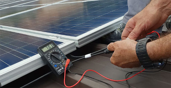
Voltage and Current Check
Before connecting solar panels to an inverter, you must measure the actual voltage and current under real-world conditions—not just rely on the panel’s sticker values. A 300W panel rated for 32V (Vmp) and 9.4A (Imp) might only produce 28V and 8A on a cloudy 25°C day, or spike to 38V on a cold morning (below 10°C) due to the -0.3% to -0.5% per °C voltage coefficient. If your inverter’s minimum startup voltage is 100V, but your string of three panels only hits 90V in warm weather, the system won’t even turn on—wasting 20-30% of potential energy.
Use a digital multimeter (accuracy ±1%) to test open-circuit voltage (Voc) first. A 72-cell panel should read 45-50V Voc in daylight, but if it shows below 40V, there’s likely shading (5-15% power loss per shaded cell) or a faulty connection (resistance > 0.5Ω reduces voltage). Next, check short-circuit current (Isc) by briefly connecting the panel’s leads to the meter in current mode. A 10A panel should measure 9-10.5A in full sun—if it’s below 7A, the panel might be dirty (5-10% loss), aged (0.5-1% annual degradation), or damaged.
Load testing is critical. Connect the panel to a DC load (like a 100W resistor) and measure operating voltage (Vmp) and current (Imp). If a 24V panel drops to 18V under load, the wiring is too thin (voltage drop > 5% per 10 feet of 12AWG cable). For strings of panels, ensure each panel’s current matches within 5%—if one panel outputs 8A while others give 9A, it’s either mismatched (10-15% efficiency loss) or failing.
Cold climates increase voltage by 10-15%, which can push a 600V-rated inverter past its limit (650V+ risks permanent damage). Always leave 10-20% buffer—if your inverter’s max input is 600V, keep the string below 540V in normal conditions. Heat does the opposite: at 40°C, a 300V string might drop to 270V, triggering inverter shutdowns if the minimum MPPT voltage is 280V.
Partial shading is a silent killer. Even 10% shading on one panel can cut a 10-panel string’s output by 30-50% due to bypass diode activation (voltage drops to 70-80% of normal). Use optimizers (cost: 50−100 per panel) or microinverters if shading is unavoidable.
Safety Precautions Needed
Working with solar panels and inverters involves high-voltage DC electricity (up to 600V), which can cause severe burns or fatal shocks (30mA can stop a human heart). Unlike AC power, DC doesn’t "cycle off"—a 300V DC shock at 10A can kill instantly, and arc flashes from faulty connections (resistance > 0.1Ω) reach 5,000°F (2,760°C), melting metal in seconds.
Hazard | Risk Level | Prevention |
Electric Shock (live wiring) | High (300-600V DC lethal) | Wear 1,000V-rated insulated gloves, disconnect all power before work |
Arc Flash (short circuits) | Extreme (5,000°F temps) | Use DC-rated breakers (10-20A per string), never disconnect under load |
Fire (faulty connections) | Moderate (15% of solar fires from bad terminals) | Torque all lugs to 25-35 Nm, check annually for corrosion (increases resistance by 50-100%) |
Overvoltage (cold weather spikes) | High (650V+ kills inverters) | Keep strings 20% below inverter max input, install 600V surge protectors |
Cell Explosions (off-grid systems) | Extreme (hydrogen gas ignites at 4% concentration) | Ventilate cell rooms, use explosion-proof fans (30+ air changes/hour) |
Grounding is non-negotiable. A 6AWG copper ground wire must connect panels and inverters to a 8-foot ground rod (resistance < 25Ω), or stray voltage can electrify metal frames (50V+ poses shock risk). Lightning strikes add 1 million+ volts—install Type 2 surge arrestors (20kA discharge capacity) at the array and inverter.
Fire safety demands attention. Solar panels keep producing 200-400V DC even during blackouts, so firefighters can’t just "turn off" a burning system. Rapid shutdown devices (required by NEC 2020) cut voltage to 30V within 30 seconds, but older systems lack this—mark clearly with "SOLAR POWERED" warnings (3-inch letters).
Cell systems bring unique dangers. A 48V lithium bank stores 25kWh—enough to vaporize tools (short circuits hit 2,000A). Always use 300A Class T fuses, keep cell rooms below 30°C (heat accelerates thermal runaway by 300%), and store 10 lbs of baking soda nearby to neutralize electrolyte leaks.
Work habits save lives. Never service panels between 10AM-2PM (peak 1,000W/m² irradiance = max voltage), and use non-contact voltage testers ($50) to confirm dead circuits. For rooftop work, harnesses (5,000-lb strength) and toe boards (3-inch height) prevent 80% of falls (15% of solar fatalities).
Proper Wiring Methods
Solar panel wiring isn’t just about connecting A to B—a single undersized wire or loose connection can slash system efficiency by 15-25% and create fire hazards. The average 10kW solar array moves 30-40A at 300-400V DC, meaning every 0.1Ω of unnecessary resistance generates 90-160W of wasted heat—enough to melt insulation over time.
Wire routing matters more than people think. Never run DC cables parallel to AC lines within 6 inches—induction creates 50-100mV of noise that confuses inverters (5-10% erratic output fluctuations). Always leave 1-inch gaps between conduits (heat buildup reduces ampacity by 15% when packed tight) and use UV-resistant MC4 connectors (last 25+ years vs. 5-7 years for cheap knockoffs).
Terminal torque is a silent killer. A 300W panel’s 10A current needs terminals torqued to 25-35 Nm—under-tightened lugs (below 20 Nm) heat up by 30-50°C, accelerating oxidation that doubles resistance in 3-5 years. But over-tightening (above 40 Nm) cracks busbars, creating micro-arcing that erodes contacts by 0.1mm annually.
String sizing requires precision. For a 48V inverter with 120-450V input range, three 36V panels in series hit 108V—too low for cold mornings where voltage spikes 15% (124V is safe). But six panels (216V nominal) risk exceeding 260V in heatwaves (MPPT stops working above 250°F). The sweet spot? Four panels (144V nominal) stays within 125-175V year-round.
"Color code everything: red for positive (+), black for negative (-), and green for ground. Reversing polarity on a 400V string sends 20A backward through diodes—a $500 repair bill waiting to happen."
Waterproofing isn’t optional. Even IP67-rated connectors fail after 5-7 years of direct rain exposure. Wrap all outdoor joints with 3M Scotchcast 88 (withstands -40°C to 90°C) and install drip loops (2-inch sag) before conduit entries—this prevents 90% of moisture-related faults (responsible for 18% of warranty claims).
Common Mistakes to Avoid
Solar installations seem straightforward until you realize 80% of DIYers make at least one critical error that cuts system output by 15-30% or worse—causes $500+ in preventable repairs. The most frequent blunder? Mismatching panel voltages in a string. When you mix a new 40V panel with older 36V models, the entire string drops to the lowest voltage (36V), wasting 10% of the new panel’s capacity. Even a 5% voltage variance between panels can trigger bypass diode failures within 2-3 years, reducing output by 20%.
Undersized wiring is another silent killer. A 5kW array pushing 20A at 250V DC needs 8AWG copper wires to keep voltage drop under 3% (NEC requirement). But many installers cheap out with 10AWG, causing 5-8% power loss (250-400W wasted) and heat buildup that degrades insulation 50% faster. In summer, when ambient temps hit 35°C, those skinny wires overheat by 20-30°C, raising resistance another 2-3% per year—a death spiral for efficiency.
Grounding mistakes account for 25% of system failures. A single unbonded panel frame can float at 90V AC leakage voltage, creating shock hazards. Proper grounding requires 6AWG bare copper wire connected to two 8-foot ground rods spaced 6+ feet apart—anything less risks lightning strikes jumping to plumbing (50kA surges melt pipes in milliseconds). And never rely on aluminum ground wires—they corrode 3x faster than copper when buried, often failing within 5-7 years.
Improper string sizing cripples inverters. A 6kW inverter with 300-600V input range needs 12 x 40V panels (480V nominal) to work optimally. But in winter at -10°C, voltage spikes 15% to 552V, dangerously close to the 600V ceiling. Meanwhile, summer heat at 40°C drops voltage to 408V—if the inverter’s MPPT minimum is 400V, you’ll lose 2-3 hours of production daily during heatwaves. The fix? 11 panels (440V nominal) keeps voltage in the 420-550V sweet spot year-round.
Neglecting maintenance costs real money. Dust buildup of just 0.1mm thickness slashes output 5-8% monthly—that's 120/year lost on a 6kW system. Rodents chew through 15% of wiring annually, triggering 200-500 repair bills. And untorqued connections loosen by 0.5-1mm annually, increasing resistance until they overheat by 40-60°C and fail. A 20 infrared thermometer used quarterly catches these issues before they become disasters.