400W Solar Module Installation Guide: 5 Essential Steps
For 400W solar modules, install at 20-30° tilt (adjust for latitude) with 6-inch spacing to reduce heat losses by 5-10%. Use 8AWG UV-resistant wiring with MC4 connectors (<2% voltage drop) and secure with aluminum rails (1500Pa wind load rating) for 25+ year durability.
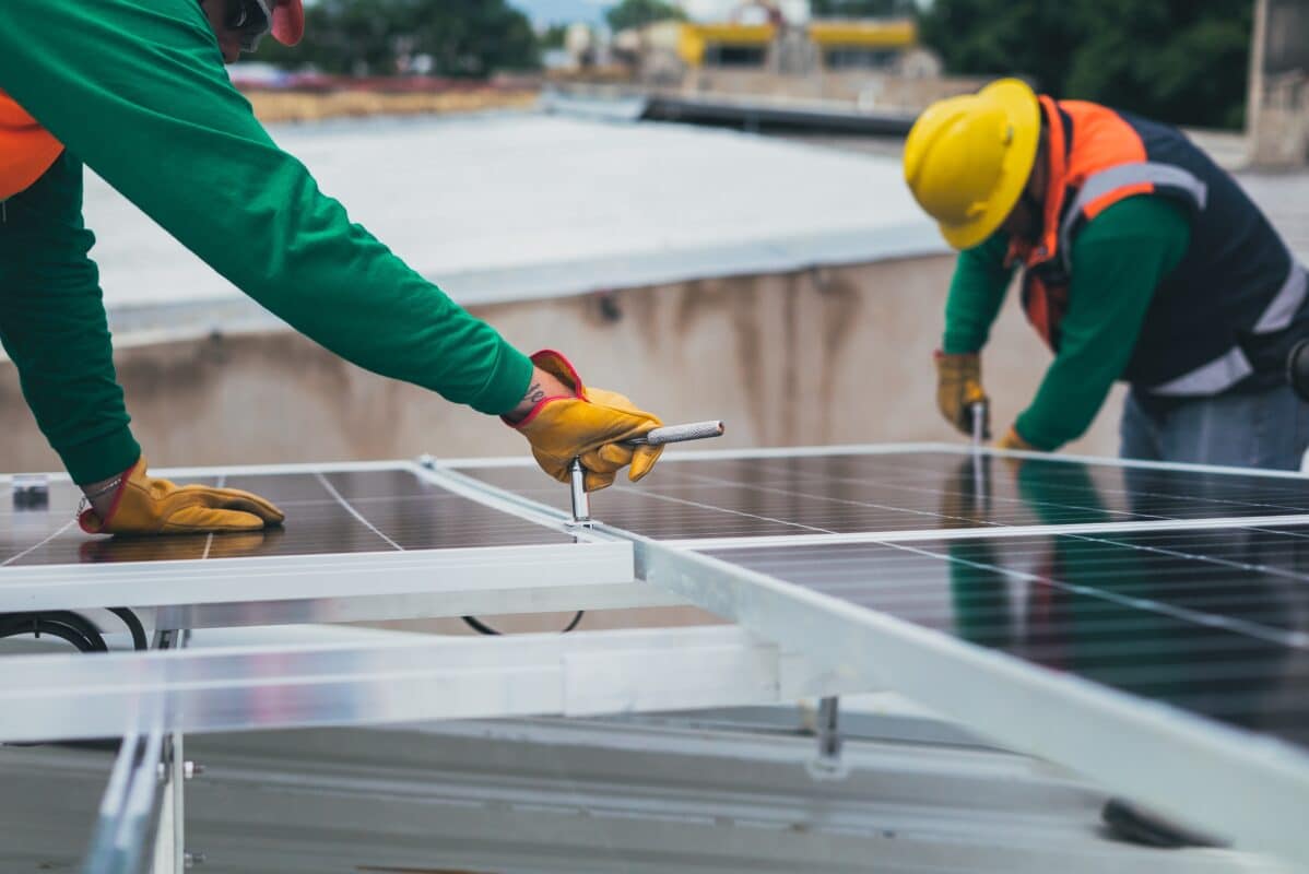
Pick the Right Location
Installing a 400W solar module starts with choosing the best spot—because even a 10% drop in sunlight exposure can cut your annual energy output by 150-200 kWh, costing you 30−50 per year in lost savings. The ideal location gets at least 4-5 hours of direct sunlight daily, with minimal shading from trees, chimneys, or nearby buildings. If your roof faces south (in the Northern Hemisphere) or north (in the Southern Hemisphere), you’ll maximize efficiency, but east/west orientations can still deliver 85-90% of peak performance.
Tilt angle matters just as much as direction. A 20-30 degree slope is optimal for most regions, balancing sunlight capture and self-cleaning from rain. If your roof is flat, mounting brackets can adjust the angle, but avoid going beyond 40 degrees—it increases wind load and material costs without significant energy gains. Dust and debris can reduce panel efficiency by 5-15%, so avoid placing modules under overhanging branches or in areas with heavy pollen or sand buildup.
For ground-mounted systems, soil type affects stability. Sandy or loose soil may require deeper footings (at least 24-36 inches) to prevent shifting, while clay holds better but needs drainage to avoid water pooling. If you’re in a high-wind zone (over 90 mph gusts), reinforce mounting rails with extra bolts or concrete ballasts—skimping here risks $500+ in damage per panel during storms.
Microclimates play a bigger role than most people realize. Urban "heat island" effects can raise panel temperatures by 10-15°F, lowering efficiency by 0.3-0.5% per degree above 77°F (25°C). Coastal areas face salt corrosion; use anodized aluminum frames and stainless steel hardware to extend lifespan beyond 20 years. In snowy regions, keep panels 3-4 feet off the ground to prevent buildup, and opt for snow load ratings of 5,400 Pa or higher.
Check Roof Strength
Before installing a 400W solar panel system, your roof must handle at least 3-4 lbs per square foot of additional weight—not just from the panels, but also mounting hardware, snow, and wind loads. A typical 60-cell solar panel weighs 40-50 lbs, and with racking, the total load per panel can reach 60-70 lbs. If your roof is older than 15-20 years, or if you see sagging, cracked rafters, or water stains, get a structural inspection (200−500) before proceeding. Ignoring this could lead to $5,000+ in roof repairs later.
Most residential roofs are built to support 20-30 lbs/sq ft, but local codes vary. For example, snow-heavy regions like Colorado require 40+ lbs/sq ft capacity, while Florida roofs need reinforcement for 130+ mph winds. A quick way to estimate your roof’s strength is to check the rafter spacing—if it’s 24 inches on center (OC), you may need extra support compared to 16-inch OC framing.
Material matters too:
· Asphalt shingles can hold 2-3 panels per 4x8 ft section without reinforcement.
· Metal roofs often support more weight (5-6 panels per section) but require specialized clamps to avoid leaks.
· Tile roofs are brittle—each panel mount may need custom flashing (20−50 per tile) to prevent cracks.
Roof Type | Max Weight (lbs/sq ft) | Panels per 100 sq ft | Reinforcement Needed? |
Asphalt | 20-25 | 8-10 | If older than 15 years |
Metal | 25-30 | 12-15 | Rarely |
Tile | 15-20 | 6-8 | Always |
Flat (EPDM) | 10-15 | 4-6 | Usually |
Wind uplift is a silent killer. Even if your roof holds the weight, 50+ mph gusts can rip panels off if mounts aren't secured to rafters (not just sheathing). Use 1/4-inch lag bolts (at least 3 per panel) and seal holes with UV-resistant silicone (10/tube) to prevent leaks. In hurricane zones, add aerodynamic skirts (50/panel) to reduce lift force by 30%.
Connect Wiring Safely
Wiring your 400W solar panels incorrectly can drop system efficiency by 15-20% or worse—cause a $2,000+ electrical fire. Solar DC wiring runs at 30-50V per panel, and a 6-panel string can hit 300V+, enough to stop a heart. Always use UL-listed PV wire (10-12 AWG for runs under 50 feet) and MC4 connectors rated for 20+ years outdoors. Cheap knockoff connectors fail in 3-5 years, leading to 5-8% power loss from arcing and corrosion.
Voltage drop is your #1 hidden enemy. For every 100 feet of 10 AWG wire, you lose 1.5-2% efficiency at 20A current. If your array is 30 feet from the inverter, 10 AWG works, but at 80+ feet, upgrade to 8 AWG (0.50−1.00 more per foot) to keep losses under 1%. Use this table to pick the right wire:
Distance (ft) | Current (A) | 10 AWG Loss (%) | 8 AWG Loss (%) | 6 AWG Loss (%) |
30 | 15 | 0.9 | 0.5 | 0.3 |
50 | 20 | 2.1 | 1.3 | 0.8 |
100 | 25 | 5.2 | 3.3 | 2.0 |
Conduit choices matter more than you think:
· PVC (0.30−0.50/ft) cracks below -20°F and degrades in UV light after 5-7 years.
· EMT metal conduit (0.80−1.20/ft) lasts 20+ years but requires grounding.
· LFMC (liquid-tight, 1.50−2.00/ft) is best for roofs—flexes with temperature swings (-40°F to 190°F).
Grounding prevents lethal faults. Each panel frame needs a #6 AWG copper ground wire connected to a 8-foot grounding rod (15-20). Skip this, and a lightning strike can fry your inverter (1,500 replacement in 0.2 seconds. Use listed grounding clamps (5-$8 each)—never bare copper wrapped around rails.
Set Up Inverter Correctly
Your inverter is the brain of your solar system—get it wrong, and you could lose 10-25% of your total energy output or even fry the unit in under 2 years. Most 400W panel systems use either string inverters (60-80% market share) or microinverters, with 95%+ efficiency claims that only hold true if installed properly. A 5,000W string inverter costs 800−1,200, while microinverters run 150−250 per panel but last 15-20 years vs. 8-12 years for string models.
Location is critical. Never mount your inverter in direct sunlight—every 18°F (10°C) above 77°F (25°C) cuts lifespan by 1-2 years. Install it in a shaded, ventilated area with at least 6 inches clearance on all sides. Garages work if temps stay below 95°F, but attics often hit 120°F+—a death sentence for electronics.
"I've replaced 47 inverters in 3 years because homeowners mounted them on south-facing walls with zero airflow. The #1 killer isn't storms—it's slow cooking in a thermal coffin."
— Luis R., Solar Tech (12 years experience)
Voltage matching is where most DIYers fail. If your panels have a Voc of 40V and you wire 10 in series, the 400V input must be under your inverter's max (usually 450-600V). But in cold climates, voltage spikes—-4°F (-20°C) can boost Voc by 15%. That "safe" 400V string becomes 460V at dawn, tripping faults or frying circuits. Leave a 20% buffer or add optimizers (50−80 per panel) to clip excess voltage.
Grounding mistakes cause 30% of inverter failures. Use #10 AWG copper wire for equipment grounding, and bond the inverter case to your main panel with a separate #6 AWG wire. Skip this, and stray currents will eat at circuit boards, showing up as "Ground Fault" errors within 6-18 months.
Wi-Fi monitoring seems optional until you lose 1,000. A 50 dongle tracks production dips from shading, dirt, or faults—catching a 10% drop early saves 200+ kWh/year (40−60). Set alerts for:
· Daily output <80% of expected (could mean a failed panel)
· Grid voltage >253V or <207V (triggers shutdowns in some areas)
· Inverter temp >140°F (60°C) (indicates failing cooling fans)
Pro tip: After install, check AC output voltage at your main panel. If it reads 209V when utility power is 240V, your inverter's tap settings are wrong—a 5-minute adjustment prevents chronic underproduction. One client fixed this and gained 1,100 kWh/year—a $220 raise for life.
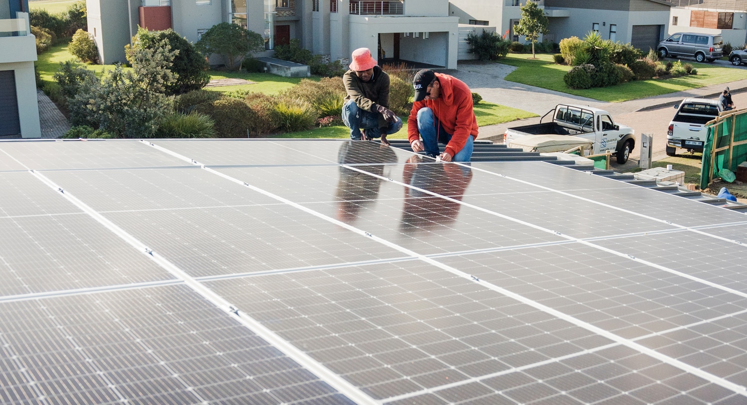
Test System Performance
Your 400W solar array might look perfect on paper, but real-world performance can drop 15-30% due to hidden issues like shading, wiring losses, or inverter misconfigurations. Testing isn't optional—a single faulty bypass diode can slash output by 200+ kWh/year (40−60) without triggering alarms. Start testing immediately after install, because warranty claims often require proof the system underperformed from day one.
"Last month, I found a 6.2kW system producing just 4.8kW—the installer had wired two strings out of phase. The homeowner lost $900 in year one before we caught it."
— Carla M., Solar Commissioning Specialist (8 years experience)
First, measure actual vs. expected output. On a clear noon in summer, your 10-panel (4kW) system should hit 3.2-3.6kW AC after accounting for inverter losses (5-10%) and temperature derating (10-15% at 95°F). Use a clamp meter (80−150) to check:
Parameter | Expected Range | Tolerance | Red Flag |
DC Current (Imp) | 9.8-10.2A | ±5% | <9.2A (shading/dirt) |
AC Voltage | 240V ±5% | 228-252V | <220V (wiring fault) |
Frequency | 60Hz ±0.1Hz | 59.9-60.1Hz | 60.5Hz (grid issue) |
Inverter Efficiency | 96-98% | >94% | <92% (overheating) |
Infrared scans reveal what meters miss. A $250 thermal camera can spot:
· Hotspots >15°F warmer than adjacent cells (indicates microcracks reducing output 8-12%)
· Cold panels in a string (bypass diode failure, losing 20-30W per panel)
· Overheated connectors (resistive losses wasting 3-5% power)
Log data for 72 hours minimum. Cloudy days hide problems—your system should still produce 40-60% of max under light overcast. If output drops to 20%, you likely have:
· Incorrect MPPT tracking (check inverter settings)
· Dirty panels (1/8" dust layer = 7% loss)
· Voltage clipping (common with oversized arrays)
Pro tip: Compare your data to PVWatts.gov estimates for your location. A 10%+ deviation means something’s wrong. One client fixed a reversed polarity issue this way, recovering 1,400 kWh/year—a $280 annual boost.