How Can You Extend the Life of Your Solar Panels
High-quality solar panels typically have a lifespan of 25 to 30 years.
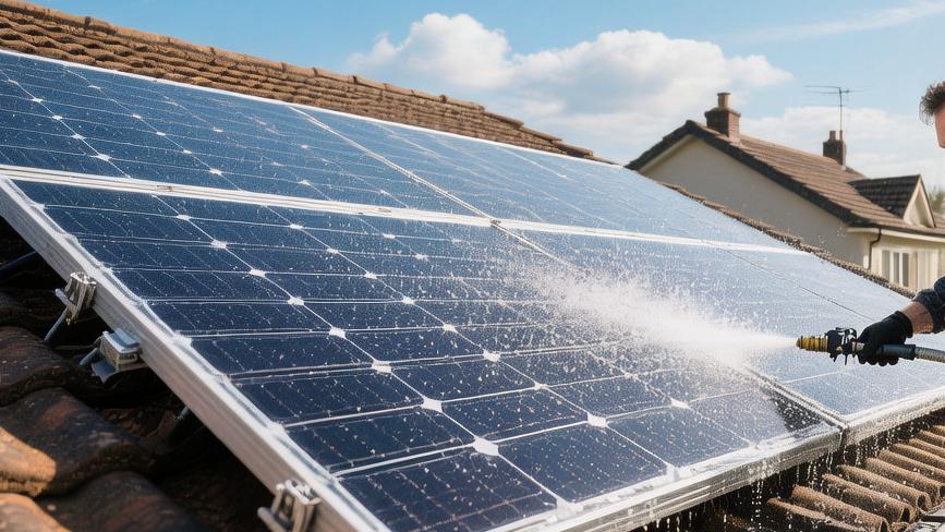
To effectively extend their service life, it is recommended to clean the surface 1 to 2 times a year using a soft brush or fresh water to thoroughly remove dust and bird droppings, preventing irreversible "hot spot" damage to the panels.
At the same time, be sure to regularly prune surrounding trees. This not only avoids power generation losses of up to 15% caused by shadow obstruction but also prevents branches from falling on windy days and causing micro-cracks in the panels.
Finally, it is recommended that a professional perform a comprehensive safety inspection of the inverter and concealed wiring every 3 years to prevent problems before they occur.
Regular Maintenance
Measuring Temperature
Using a handheld infrared thermal imager with a thermal sensitivity of 0.1 degrees Celsius, scan at a distance of 3 to 5 meters from the panels during midday when solar radiation intensity reaches over 600 watts per square meter.
The variance of the surface temperature distribution for normal monocrystalline silicon modules should be within 2 degrees Celsius.
If the infrared screen shows a localized temperature of a cell that is 15 to 20 degrees Celsius higher than the surrounding area, a power-loss hot spot has formed.
Temperature anomalies are usually caused by 0.5 mm internal welding defects or stubborn stains covering an area equal to 2% of a single cell.
At an operating voltage of 30 Volts, a persistent high-temperature hot spot will trigger the bypass diode, causing the series circuit to lose 33.3% of its rated power output.
Troubleshooting anomalies requires executing three quantitative detection indicators:
· Connect a multimeter in series to the circuit to test the short-circuit current. If it drops sharply from the normal 10 Amps to 6.5 Amps, it represents physical damage to the internal PN junction.
· Measure the open-circuit voltage across the panel. If the reading is more than 10 Volts lower than the factory nominal value of 42 Volts, it indicates that the bypass diode has been in a conducting and heating state for a long time.
· Calculate the power generation difference within a 30-day safety period, record the output curve for 5 peak hours daily, and submit time-stamped data records to the manufacturer to apply for a warranty replacement.
Finding Cracks
Micro-cracks in the glass with a width of less than 50 micrometers cannot be seen by the naked eye; an electroluminescence (EL) tester equipped with a high-resolution near-infrared lens must be used.
In an environment with illuminance lower than 0.1 lux at night, apply a reverse DC bias voltage of 500 Volts to the array to let the silicon wafers emit infrared light with a wavelength between 1000 nm and 1200 nm.
Intact silicon wafers appear as a uniform grayish-white in the image, while micro-cracks block the electron transmission path, showing fault lines with a width exceeding 2 mm.
After coastal areas endure hurricanes with wind speeds greater than 30 meters per second, or experience limit snow load tests of 5400 Pascals per square meter, the probability of internal silicon wafer physical fracture increases by 12%.
A web-like crack spanning an entire 156 mm size cell, after approximately 150 thermal expansion and contraction cycles, will cause a 5% to 8% power attenuation in a 400 Watt module.
The standard operating procedure for troubleshooting hidden dangers includes several rigorous parameter comparisons:
· Count the number of dendritic cracks longer than 5 cm in the image. If a single module has more than 3, the expected lifespan will be shortened by 40%.
· Calculate the area ratio of the black failure zone on a single silicon wafer. A blind zone exceeding 15% will result in an increase of 0.3 Ohms in the series resistance of the entire panel.
· Compare with historical archived photos from 24 months ago to measure the spread rate of micro-cracks. If the annual growth length exceeds 10 mm, it must be marked as a high-risk monitoring object.
Tightening Screws
Panels are installed on roofs with a tilt angle of 15 to 30 degrees, with aluminum alloy rails and 304 stainless steel pressure clamps forming the load-bearing skeleton.
After enduring approximately 40 occurrences of level 8 gale-force winds annually, the alternating stress at the connections will cause the nuts to undergo tiny vibrational retreats.
Carry a digital display torque wrench with a range of 5 to 25 Nm to verify each of the 16 end clamps on the outer edges and the 24 mid-clamp bolts between adjacent internal panels.
Standard manuals require M8 socket head cap screws to reach a tightening torque of 14 to 16 Newton-meters.
When the wrench shows the residual torque of a bolt is lower than 10 Newton-meters, it indicates that the fixed clamp has developed a gap loosening of approximately 0.5 mm.
At wind speeds of 25 meters per second, this gap can cause the panel to produce low-frequency resonance approximately 5 times per second.
10 hours of continuous resonance subjects the 3.2 mm thick tempered glass to more than 15 MPa of alternating tensile stress, causing the probability of glass spontaneous explosion to soar to 2%. Tightening operations need to follow specific physical stress standards:
· Clean dust and sand with a thickness exceeding 2 mm inside the rail grooves to prevent the reduction of the friction coefficient, which could cause the clamps to slip when subjected to 150 kg of lateral thrust.
· Use spring washers with anti-rust and anti-loosening coatings to provide a pre-tightening force of about 800 Newtons, offsetting thermal expansion deformation caused by a 60-degree Celsius temperature difference.
· Spend 45 minutes every 12 months using the diagonal cross method to re-tighten all 40 fixed nodes, ensuring that stress is evenly distributed across every square meter of wind-exposed area.
Monitor Your Inverter
Checking Indicator Lights
The front panel of a 5 kW residential inverter is usually equipped with 3 to 5 LED operating status indicator lights that emit green light with a wavelength of approximately 520 nm.
Every morning at 7:30 AM, when solar radiation intensity reaches 200 Watts per square meter, the PV DC input voltage will cross the 150 Volt startup threshold.
The microprocessor must complete the system self-check within a delay cycle of approximately 1.5 seconds, after which the green light flashing frequency increases from 30 times per minute to a steady state.
During working hours, a red light representing a fault flashes at intervals of 0.5 seconds, meaning the internal circuit has detected a residual leakage current higher than 30 mA.
An error code consisting of 4 Arabic numerals will then pop up on the screen; for example, error code "E031" indicates the grid frequency has exceeded the deviation range of plus or minus 0.5 Hz from the 60 Hz standard value.
Continuously recording the frequency distribution of a single red light lighting up within 48 hours can estimate that the wear rate of the AC side relay switch contacts has increased by approximately 12%.
Listening to Sounds
When the internal inverter bridge processes 4,000 Watt-hours of DC charge conversion per hour, it generates thermal energy loss of approximately 2% of the total input power.
Two 80 mm diameter brushless DC cooling fans at the bottom of the casing will start on time when the internal sensor detects that the heat sink temperature has reached 45 degrees Celsius.
Ambient noise decibel values measured at a test point 1 meter from the device should be stable between 35 dB and 40 dB, with fan speeds maintained at a median level of 2500 rpm.
The 0.5 grams of grease added inside the bearings will see its viscosity parameter drop by approximately 40% after 3 years and about 15,000 hours of rotational friction.
When the measured acoustic amplitude exceeds a peak of 50 dB and sharp high-frequency noise above 200 Hz appears on the acoustic spectrum, it indicates that the roundness error of the balls has exceeded 0.01 mm.
The actual exhaust volume of the fan will drop sharply from the standard 120 cubic meters per hour to around 70 cubic meters, causing the temperature around the device motherboard to climb at a rate of 1.5 degrees Celsius per hour.
Calculating Conversion Rates
Modern string inverters, when loaded within the 50% to 100% rated load range, usually have a factory-rated maximum weighted efficiency value locked between 97.5% and 98.2%.
Retrieve the statistical samples from the past 30 days from the background mobile software, and extract the ratio of input power to output power between 12:00 PM and 1:00 PM every day.
The real-time DC power transmitted down from the roof module array shows as 4,200 Watts, while the grid-connected power recorded by the AC side meter is only 3,950 Watts. Dividing these results in an actual conversion rate of 94.04%.
The measured value of 94.04% shows a negative deviation of 2.96% from the 97% minimum efficiency guarantee marked on the device nameplate.
There is an 85% probability that the physical reason for the approximately 120 Watts of electricity disappearing into thin air is that the capacity of the aluminum electrolytic capacitors used internally for filtering has decayed by more than 20% of the initial nominal value.
The lost 120 Watts of power, calculated based on 5 hours of full-load operation per day, will result in a power generation gap of 219 kWh accumulated over 365 days a year, equivalent to an annual loss of about $35 in electricity revenue.
Prevent Physical Damage
Avoiding Hail
Meteorological bureau statistics show that when hailstones with a diameter exceeding 25 mm hit a roof with a tilt angle of 20 degrees at a terminal velocity of 20 meters per second, they produce approximately 15 Joules of instantaneous kinetic energy.
Although standard 3.2 mm thick low-iron tempered glass passes a 25 mm hail impact test fired at 23 meters per second before leaving the factory, ice chunks exceeding 35 mm will cause the localized pressure on the glass surface to break the physical limit of 120 MPa within 0.01 seconds.
Broken glass not only causes light transmittance to plummet from 98% to below 40%, but also causes the internal monocrystalline silicon wafers to develop star-shaped radioactive cracks with a width exceeding 2 mm and a length between 10 and 15 cm.
According to the meteorological sample distribution over the past 10 years, installing upgraded double-glass modules with a thickness of 4.0 mm in hail-prone areas can lower the probability of a single panel being scrapped due to extreme weather from 4.5% to around 0.8%.
Sample data from insurance claims over the past 60 months show that spending $400 to install a layer of 50 mm aperture protective mesh woven from 0.8 mm diameter stainless steel wire for a 5 kW system can reduce panel replacement costs—totaling about $3,000 in value—by 85% during hailstorms with wind speeds of 80 km/h.
Do Not Step on Them
When a 75 kg adult stands with both feet on a photovoltaic panel with an area of about 1.6 square meters, the contact area between the soles and the glass is only 0.03 square meters, which generates a static pressure as high as 24,500 Pascals at the contact point.
The load-bearing support limit design value between the aluminum alloy frame at the bottom of the panel and the backplane is typically 5400 Pascals per square meter. Concentrated force will cause a downward physical deformation of more than 1.5 cm in the center area.
When bending deformation exceeds the silicon wafer's own 0.1% yield strain limit, the 160-micrometer-thick silicon wafer will develop about 50 web-like hidden cracks with widths of 10 to 30 micrometers internally.
Panels with hidden cracks may see their average daily power generation drop by only 0.5% in the first year, but after experiencing 365 daily 60-degree Celsius high-low temperature cycles, the hidden cracks will continue to expand along the crystal lattice direction at a rate of 2 mm per year.
Laboratory power attenuation test curves prove that hidden crack areas caused by illegal stepping, accounting for 5% of a single silicon wafer's area, will evolve into permanent hot spots with temperatures as high as 85 degrees Celsius after 36 months, leading to a permanent reduction of 12% to 15% in the peak output power of the entire 400 Watt module.
Preventing Strong Winds
Spring gusts averaging 15 meters per second, mixed with dead branches weighing between 200 and 500 grams, hit the surface of modules 1.5 meters from the edge of the roof at a relative speed of 54 km/h, generating a peak impact force of up to 80 Newtons.
In extreme weather where wind speeds soar to 30 meters per second, the back of a single 2-square-meter panel will endure an upward wind uplift force of up to 1200 Pascals, equivalent to 240 kg of vertical tension tearing at 4 aluminum alloy fixed clamps.
When the torque of the fixed bolts is lower than the standard lower limit of 12 Newton-meters, high-frequency vibration of about 3 times per second brought by the wind load will cause the fasteners to undergo a displacement slip of about 2 mm within 72 hours.
Every 6 months, spending about $150 to hire professionals to prune all overhanging branches with a diameter exceeding 3 cm within a 4-meter radius of the system can control the statistical probability of glass breakage caused by foreign object impact from 2.5% per year to a safe interval of 0.1%.
Model parameters from aerodynamic wind tunnel experiments show that reserving an air convection gap of 15 cm to 20 cm between the panels and the roof can weaken the Bernoulli negative pressure effect generated when gusts blow by 30%, while relying on a natural wind speed of 0.5 meters per second to take away about 15% of the waste heat from the module surface, causing the operating temperature to drop by 3 to 5 degrees Celsius.