N-Type Solar Modules at High Altitude | UV Exposure, Temperature Swings, Output Stability
Photovoltaic plants above 3,000 meters can face stronger ultraviolet radiation, large day-to-night temperature changes, snow, hail, wind, and difficult maintenance conditions. The U.S. Environmental Protection Agency uses an indicative increase of about 6% in UV intensity for every kilometer of elevation in its UV Index calculation, but this value should not be treated as a direct conversion factor for the broadband UV dose received by photovoltaic materials.[1]
Altitude alone does not determine module reliability. Actual exposure also depends on latitude, season, ozone, clouds, aerosols, wind, terrain, snow cover, module tilt, and mounting configuration.
This article mainly discusses utility-scale N-type TOPCon modules. HJT, IBC, n-PERT, and other N-type technologies can behave differently because their passivation layers, contacts, encapsulation systems, and temperature characteristics are not identical.
High-altitude stress | Main reliability concern | Evidence required during procurement |
Higher UV exposure | Passivation damage, polymer discoloration, coating deterioration, and backsheet cracking | Extended UV and sequential-stress results for the exact module bill of materials |
Large temperature swings | Power derating, solder fatigue, seal movement, and cell cracking | Verified temperature coefficients, thermal-cycle results, and site-specific thermal modeling |
Snow, hail, and wind | Glass breakage, frame deformation, mounting failure, and electrically active cell cracks | Site load calculations, mechanical-load qualification, and enhanced hail testing where required |
Dust and snow cover | Soiling loss, shading, mismatch, hot spots, and reduced rear irradiance | Soiling measurements, cleaning strategy, and front- and rear-side irradiance monitoring |
High system voltage | Potential-induced degradation and insulation stress | PID testing for the exact module construction, polarity, system voltage, and environmental conditions |
An N-type label does not guarantee high-altitude reliability. The cell, glass, encapsulant, interconnection, edge seal, junction box, frame, mounting system, and manufacturing process must be evaluated as one complete product.
UV Exposure
Stronger Sunlight
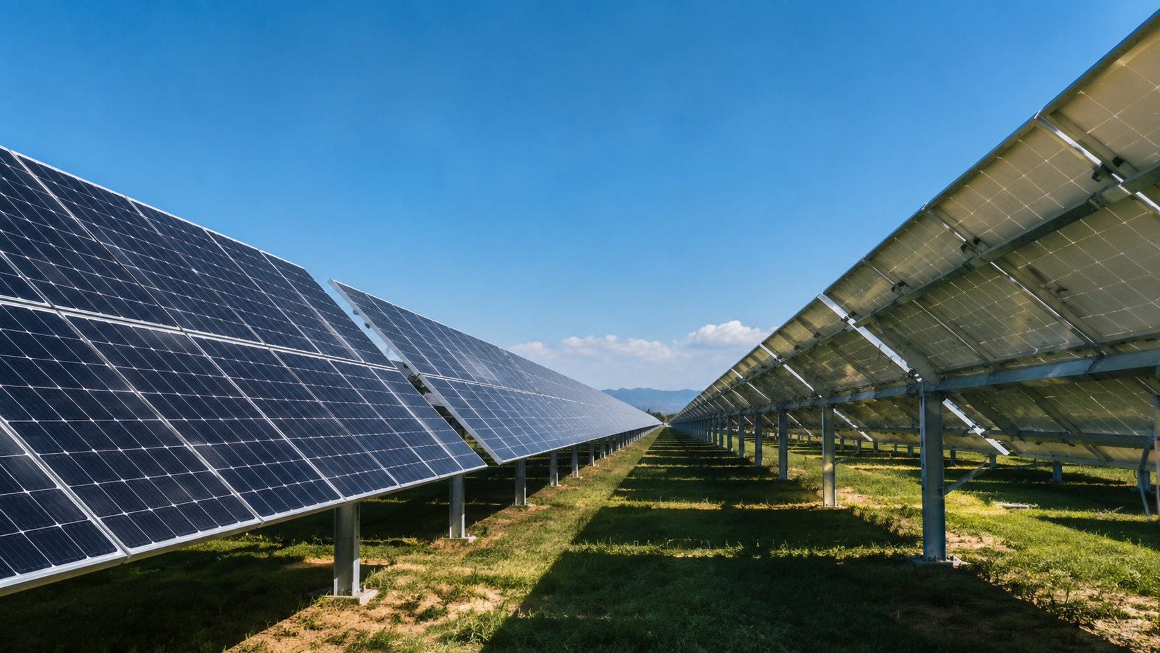
At higher elevations, the shorter atmospheric path generally reduces the scattering and absorption of ultraviolet radiation. Snow-covered ground can also increase reflected radiation around the module, particularly for bifacial systems.
However, a simple percentage increase by elevation cannot predict the service-life UV dose. Project teams should use measured or modeled spectral irradiance whenever the expected exposure is materially different from the climates represented by ordinary module qualification.
IEC 61215-1 defines design-qualification requirements for terrestrial PV modules, but it explicitly states that the useful service life of a qualified module depends on its design, environment, and operating conditions. Passing IEC 61215 is therefore not a quantitative prediction of module lifetime.[2]
The IEC 61215 UV preconditioning test uses a total UV dose of approximately 15 kWh/m² across the 280–400 nm wavelength range. This exposure is useful for qualification, but it represents only a limited fraction of long-term outdoor exposure and may not reveal every UV-sensitive degradation mechanism.[3]
Recent research has shown that modern high-efficiency cell architectures can be vulnerable to UV-induced degradation. UV radiation can damage dielectric passivation layers or their interfaces with silicon, increasing surface recombination and reducing cell output. The severity varies substantially among cell designs, material combinations, and manufacturing processes.[4]
IEA PVPS reviewed tests in which commercial TOPCon modules showed power losses ranging from about 0.5% to 8% after a 60 kWh/m² UV dose. The wide range demonstrates that UV resistance is product-specific rather than an inherent property of all TOPCon modules.[5]
These accelerated results should not be directly converted into a fixed number of outdoor years. Laboratory and field exposure differ in spectrum, temperature, humidity, electrical operating state, exposure direction, and interaction with other environmental stresses.
For high-altitude procurement, an extended UV review should include:
· the accumulated dose and wavelength range;
· front-side and rear-side exposure conditions;
· module temperature during testing;
· open-circuit, short-circuit, or maximum-power operating state;
· power stabilization before and after exposure;
· changes in power, current, voltage, spectral response, and electroluminescence;
· the exact cell, glass, encapsulant, metallization, and coating combination;
· sequential testing with damp heat, thermal cycling, humidity-freeze, or PID stress.
IEC 62788-1-7 provides accelerated-weathering procedures for evaluating the optical durability of photovoltaic polymeric materials. Its purpose is to support more meaningful assessment of material weathering than relying only on the limited UV exposure included in basic module qualification.[6]
Module glass and encapsulation must balance two objectives: transmitting wavelengths that the solar cell can use and limiting harmful short-wavelength exposure to sensitive materials. A single total-transmittance value cannot describe this balance.
Buyers should request spectral-transmittance curves before and after aging, together with coating adhesion, abrasion resistance, humidity resistance, yellowness, haze, and UV cutoff data.
UV Aging Risks
UV radiation, heat, oxygen, and moisture can change the optical, electrical, and mechanical properties of module polymers. Encapsulant discoloration reduces the light reaching the cell, while adhesion loss can encourage delamination, corrosion, and moisture ingress.
EVA, POE, TPO, and co-extruded encapsulants should not be treated as uniform material categories. Their durability depends on the base polymer, additives, UV absorbers, stabilizers, crosslinking, lamination conditions, thickness, adhesion, and compatibility with the cell and glass.
Polyolefin encapsulants generally offer similar or higher volume resistivity and lower water-vapor transmission than conventional EVA. They also avoid acetic-acid formation because they do not contain vinyl acetate groups. However, accelerated tests have produced mixed results, showing that additives and the complete module design can be as important as the polymer family.[7]
Polymeric backsheets can chalk, crack, delaminate, or lose insulation performance after combined UV, heat, humidity, and mechanical exposure. The failure rate depends on the backsheet chemistry, layer construction, climate, installation, and manufacturing quality.[8]
Glass-glass modules remove the polymeric backsheet and therefore eliminate backsheet chalking and backsheet cracking. They do not eliminate rear-side reliability risks.
Glass-glass modules still require evaluation of:
· front- and rear-glass thickness;
· thin-glass breakage;
· edge-seal durability;
· encapsulant adhesion and delamination;
· perimeter moisture ingress;
· cell and interconnection stress;
· frame and clamp compatibility;
· transport and installation damage.
IEA PVPS identifies glass breakage, cell cracks, delamination, encapsulant discoloration, backsheet failure, junction-box defects, bypass-diode faults, contact corrosion, and PID as separate but interacting failure modes. Removing one vulnerable component does not remove the need to qualify the complete module.[5]
TOPCon modules also require careful evaluation of front-contact corrosion. Recent studies reviewed by IEA PVPS found large differences in damp-heat performance among TOPCon modules with different encapsulants and rear structures. This variation shows why the same cell technology can produce very different reliability results when the surrounding materials change.[5]
Junction boxes, connectors, cable insulation, and seals face the same combined UV and temperature stresses. Visual discoloration alone cannot confirm safety because impact strength, sealing force, insulation resistance, and adhesion may deteriorate before obvious external damage appears.
Incoming inspection should verify:
· material and component traceability;
· junction-box and connector ratings;
· ingress-protection performance;
· cable pull resistance;
· bypass-diode thermal performance;
· adhesion to the module rear surface;
· retained properties after UV, damp heat, and thermal cycling.
IEC 62941 establishes quality-system requirements for module design, manufacturing, material selection, and process control. These controls are essential when a certified product is manufactured with a different cell, glass, encapsulant, junction box, sealant, or other component from the originally qualified design.[9]
IEC TS 62915 provides a uniform approach for determining whether changes to an already qualified module require partial or full retesting. Procurement contracts should therefore require disclosure and approval of bill-of-material changes rather than accepting modules solely because the model name remains unchanged.[10]
Glass Protection
Front glass provides optical transmission, environmental protection, electrical insulation, and mechanical support. Its long-term performance depends on composition, thickness, tempering, surface texture, edge quality, anti-reflective coating, module size, and mounting configuration.
Anti-reflective coatings can improve transmission, but initial performance alone does not prove durability. High-altitude projects should evaluate retained transmission after UV exposure, abrasion, thermal cycling, humidity, cleaning, blowing sand, and any site-specific salt or ammonia exposure.
Impact resistance must be compared with the site's actual hail risk. The ordinary IEC 61215 hail test is a baseline qualification test and does not represent every severe storm. IEC TS 63397 defines additional qualification guidance for sites where modules may experience hail impacts beyond the normal IEC 61215 test envelope.[11]
Hail resistance depends on:
· front-glass thickness and tempering quality;
· cell-to-glass distance;
· encapsulant stiffness;
· module dimensions and unsupported span;
· frame stiffness;
· clamp position and rail spacing;
· module tilt and storm direction.
Double-glass construction may distribute mechanical load more evenly in some designs, but it does not guarantee better hail resistance. The exact module and mounting configuration must be tested.
Soiling behavior also depends on glass texture, surface energy, tilt, rainfall, dust composition, dew, and cleaning practices. Static water-contact angle alone cannot demonstrate self-cleaning performance because a surface may show a high contact angle while still retaining droplets and dust.
IEA PVPS estimated that soiling caused at least 3% to 4% of worldwide annual PV energy production losses in 2018. Site-level losses vary widely, and arid locations without adequate cleaning can experience much greater losses.[12]
A fixed monthly cleaning schedule is therefore not suitable for every project. Cleaning should be based on measured soiling loss and an economic comparison between recovered energy and the costs of water, labor, access, coating wear, and possible module damage.
Glass and coating acceptance should include:
· initial and aged spectral transmission;
· abrasion and scratch resistance;
· coating adhesion;
· haze and yellowness changes;
· rolling-angle or contact-angle-hysteresis behavior where relevant;
· compatibility with the planned cleaning method;
· site-specific soiling-rate measurements.
Temperature Swings
Hot Weather
Module power decreases as cell temperature rises. A simplified relationship is:
P(T) ≈ PSTC × [1 + γPmax × (Tcell − 25°C)]
In this expression, γPmax is the maximum-power temperature coefficient. Because the coefficient is normally negative, a less negative value produces a smaller temperature-related power loss.
Many current N-type products have a less negative power-temperature coefficient than conventional PERC modules. However, the actual coefficient must be taken from the tendered module's verified data and should not be assigned solely from the N-type or P-type label.
Measured current-voltage curves should be corrected for irradiance and temperature using recognized procedures. IEC 60891 defines methods for translating measured I-V characteristics to different temperature and irradiance conditions.[13]
High altitude does not automatically mean higher operating temperature. Strong solar irradiance can raise cell temperature, while lower ambient temperature and stronger wind can improve convective cooling. Rear ventilation, mounting clearance, ground reflectance, module construction, and wind conditions can be as important as elevation.
Annual energy estimates should therefore use hourly or sub-hourly weather data and a validated module-temperature model. A single midday temperature measurement should not be applied across the entire year.
IEC TS 63126:2025 provides enhanced qualification guidance for modules, components, and materials used at high operating temperatures. It defines Level 1 for installations with a 98th-percentile module temperature of no more than 80°C and Level 2 for installations with a 98th-percentile temperature of no more than 90°C.[14]
Projects should estimate the 98th-percentile module temperature for the actual site and mounting design before deciding whether ordinary IEC 61215 qualification is sufficient.
Hot spots develop when a cell or substring is forced into reverse bias. Common causes include:
· bird droppings and localized dirt;
· partial snow cover;
· vegetation or structural shading;
· cell cracks and solder defects;
· electrical mismatch;
· failed or incorrectly selected bypass diodes.
Uniform cloud cover usually reduces irradiance across an entire array and is less likely to create severe reverse-bias stress than localized shading. Cloud-edge effects and rapidly moving partial shadows can still create nonuniform operating conditions.
Bypass-diode quantity and cell coverage are circuit-design choices, not inherent N-type characteristics. Buyers should review substring layout, diode current and temperature ratings, junction-box heat dissipation, partial-shading test results, and infrared behavior under representative shading patterns.
IEA PVPS reports that partial shading can cause energy loss, reverse-bias stress, hot spots, and bypass-diode activation. The resulting effect depends on module layout, inverter operation, shading geometry, and electrical protection.[15]
Thermal imaging should be combined with electrical measurements, visual inspection, and electroluminescence where necessary. A warm cell is not automatically a failed cell, and a transient temperature difference should be distinguished from a persistent hot spot.
Glass-glass modules should not automatically be assumed to operate cooler than glass-backsheet modules. Rear-glass thickness, emissivity, rear irradiance, thermal mass, wind exposure, mounting clearance, and frame design can increase or reduce operating temperature.
Cold Nights
High-altitude modules can experience low night temperatures and rapid transitions from cold nights to strong daytime irradiance. Repeated expansion and contraction place stress on cells, solder joints, interconnection ribbons, encapsulants, glass, frames, and seals.
Low temperature alone does not prove that a module will crack. Crack initiation and propagation also depend on:
· wafer thickness and format;
· pre-existing manufacturing defects;
· cell interconnection design;
· soldering stress;
· encapsulant modulus;
· glass thickness and support;
· transport vibration;
· snow and wind loading;
· clamp position and installation torque.
A fixed claim that N-type cells have a certain percentage lower cracking rate than PERC is not justified without controlled module-level evidence. Mechanical behavior is governed by the complete laminate, interconnection, frame, and mounting system rather than wafer doping alone.
Sealants and edge materials should be selected by verified performance rather than by brand. The review should include adhesion to the actual glass and frame finishes, low-temperature movement capability, moisture resistance, UV resistance, cure conditions, and retained adhesion after environmental cycling.
Cold weather also affects electrical design because module open-circuit voltage increases as cell temperature falls. Maximum string length must therefore be calculated using the project's minimum design temperature and the module's verified open-circuit-voltage temperature coefficient.
IEC 62548-1 establishes design requirements for PV arrays, including DC wiring, electrical protection, switching, earthing, mounting structures, bifacial modules, and anti-PID equipment. Its requirements should be applied together with local electrical and structural codes.[16]
Low-temperature qualification should also cover:
· cable-jacket flexibility;
· connector sealing and compatibility;
· moving cable loops on tracking systems;
· junction-box adhesion;
· tracker drive and lubricant temperature limits;
· inverter cold-start capability and altitude derating.
Inverter, tracker, and communication downtime should be reported separately from module degradation. Combining them can make a reliable module appear to underperform or can hide an actual module defect behind a system-availability problem.
Cracking Risk
Cell cracks can interrupt current pathways, isolate active cell area, increase resistance, and create conditions for later corrosion or hot spots. However, not every crack visible in an electroluminescence image causes immediate power loss.
Cracks should be classified by:
· orientation and length;
· whether they cross fingers or interconnection points;
· the proportion of electrically isolated cell area;
· changes under mechanical loading;
· measured power or resistance impact;
· evidence of corrosion or localized heating.
Counting every visible crack as an equal failure can overstate its immediate effect. Ignoring electrically inactive cracks can also understate the possibility of later propagation under thermal or mechanical stress.
IEA PVPS identifies larger module formats, thinner wafers, thinner glass, and rapidly changing interconnection designs as important mechanical-reliability concerns. These risks must be assessed at module level rather than inferred from the cell technology name.[17]
Mechanical-load qualification must be connected to the site's actual design load. Engineers should distinguish among:
· site design load;
· module test load;
· front-side and rear-side loading;
· uniform pressure and uneven snow accumulation;
· static and cyclic loading;
· the safety factors required by local codes.
IEC 61215-2 includes static and cyclic mechanical-load testing, but the result applies to the tested mounting configuration and test conditions. A qualified module can still fail if rail spacing, clamp zones, bolt torque, foundation movement, or snow distribution differs from that configuration.[18]
Transport and handling can introduce cell cracks before commissioning. Packaging should therefore be validated against expected road vibration, shock, stacking, unloading, secondary transport, and on-site handling.
Arrival inspection should define:
· acceptable pallet and packaging damage;
· electroluminescence defect classes;
· the initial sample size;
· triggers for expanded sampling or full inspection;
· acceptable power deviation;
· responsibility for latent transport damage;
· rules for product and material substitutions.
A fixed foam thickness or one universal acceptance-quality limit cannot replace route-specific packaging validation and clearly defined defect classes.
Output Power Stability
Operational and Persistent Losses
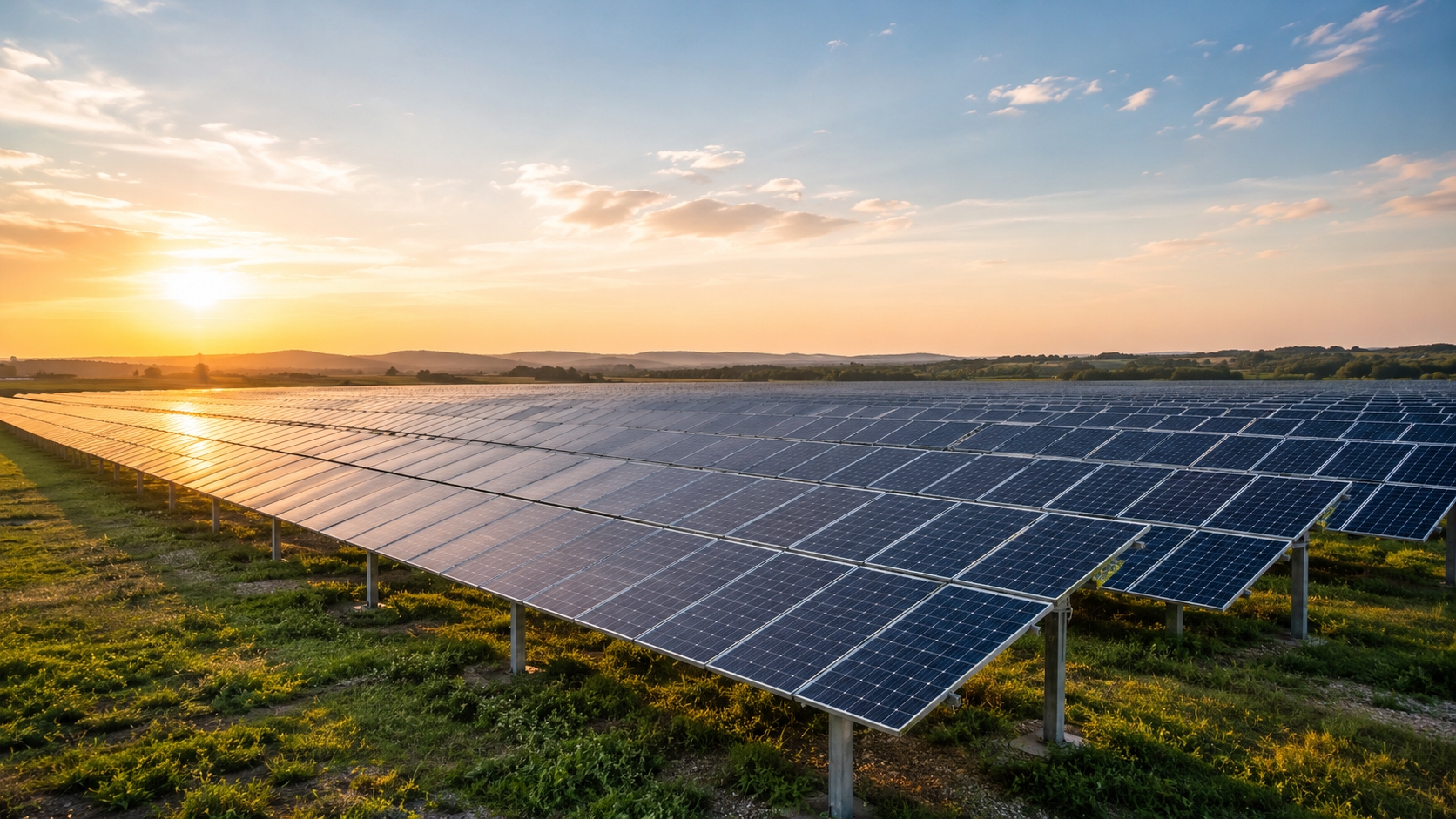
PV output loss must be divided by mechanism and timescale. Temperature derating, temporary snow cover, shading, and most soiling losses are reversible. Corrosion, delamination, cell isolation, failed interconnections, and some forms of PID can produce persistent or permanent losses.
Loss category | Examples | Preferred evaluation method |
Short-term reversible loss | High cell temperature, temporary snow cover, dust, and shading | Weather-normalized monitoring and soiling measurement |
Recoverable electrical loss | Some PID modes and metastable light-induced effects | Controlled stress, stabilization, and recovery testing |
Persistent module degradation | Corrosion, delamination, isolated cell area, coating damage, and failed interconnections | Long-term performance analysis supported by module inspection |
System availability loss | Inverter outages, tracker faults, communication loss, and curtailment | Event logs and plant availability analysis |
These categories should not be combined into a fixed “daily loss budget.” Such a calculation would mix instantaneous, seasonal, recoverable, permanent, and system-side effects.
IEC 61724-1 defines terminology, equipment, and methods for PV performance monitoring. The current edition includes updated irradiance-sensor requirements and specific provisions for soiling and bifacial-system monitoring.[19]
A valid N-type and PERC comparison should normalize output for:
· nameplate power and initial stabilization;
· front and rear plane-of-array irradiance;
· cell or module temperature;
· soiling and snow cover;
· inverter availability and clipping;
· curtailment;
· tilt, row position, and string position;
· electrical mismatch;
· sensor and measurement uncertainty.
PID is influenced by the voltage relative to ground, polarity, temperature, humidity, illumination, glass composition, encapsulant resistivity, grounding configuration, and exposure time. Moving from a 1,000 V to a 1,500 V system increases the possible electrical potential, but it does not create a universal 1.5-times or 2.25-times degradation rate.
TOPCon modules should not be described as universally PID-free. Passivated cell structures can experience polarization-related PID and other high-voltage degradation modes, depending on cell design and module construction.[5]
IEC TS 62804-1:2025 defines test procedures for detecting PID in crystalline-silicon modules with passivating dielectric layers. Procurement specifications should state the test method, voltage polarity, temperature, humidity, illumination, duration, and post-test recovery procedure.[20]
Soiling and cleaning should be managed through measured losses rather than a fixed schedule. Cleaning is justified when the expected value of recovered energy exceeds water, labor, access, coating-wear, and module-damage costs.
Bifacial rear-side production can increase energy yield but must not be treated as a fixed bonus. Rear-side performance depends on:
· module bifaciality;
· ground albedo and snow persistence;
· row height, spacing, and tilt;
· tracking strategy;
· rear shading from structures and cables;
· rear-side soiling;
· irradiance nonuniformity and electrical mismatch.
IEA PVPS notes that rear irradiance is normally less uniform than front irradiance and that structural shading, albedo, module spacing, and mismatch must be included when modeling bifacial yield.[21]
Low Degradation
Warranty decline, initial stabilization, field performance loss, and permanent material degradation are related but different metrics.
Metric | Meaning |
Warranty degradation | The maximum decline allowed under the manufacturer's warranty |
Initial stabilization | Early power change caused by light, temperature, or metastable cell behavior |
Field performance loss rate | The weather-normalized change measured during actual operation |
Permanent material degradation | Irreversible loss caused by corrosion, cracking, delamination, optical damage, or electrical failure |
A warranty value should not be presented as the expected field degradation rate. Field estimates are affected by the observation period, weather correction, cleaning, availability, curtailment, missing data, sensor drift, and statistical method.
NREL research on recent PV technologies found that early-life behavior can differ among module types and may not represent the later long-term degradation rate. Comparisons therefore require consistent stabilization procedures, measurement periods, and environmental normalization.[22]
Classic boron-oxygen light-induced degradation mainly affects boron-doped Czochralski silicon. Phosphorus-doped N-type wafers largely avoid this specific mechanism, but gallium-doped P-type wafers have also greatly reduced its importance in modern PERC products.
IEA PVPS reports that classic boron-oxygen LID now has relatively low importance in most current gallium-doped P-type and N-type products. LeTID is a separate hydrogen-related mechanism that mainly affected earlier P-type PERC modules, while current TOPCon modules are generally less susceptible.[5]
Reduced LID or LeTID risk does not guarantee low total degradation. Current high-efficiency modules must also be assessed for:
· UV-induced degradation;
· PID and polarization effects;
· metallization and interconnection corrosion;
· encapsulant and cell-material interaction;
· thin-glass breakage;
· cold or defective solder joints;
· edge-seal and adhesion failure.
N-type modules are not immune to degradation. Their dominant degradation mechanisms may differ from those of older PERC modules, and the risks vary among products with different materials and processes.
Any claimed degradation advantage should disclose:
· the number of modules and sites studied;
· module models and manufacturing dates;
· complete bill-of-material families;
· commissioning and stabilization procedures;
· weather and soiling normalization;
· treatment of outages and curtailment;
· meter and sensor uncertainty;
· confidence intervals for the estimated loss rate.
Long-Term Yield
Long-term yield is not determined by degradation rate alone. A bankable comparison should combine:
1. initial module efficiency and rated power;
2. spectral and low-light response;
3. power-temperature coefficient;
4. bifacial response and rear irradiance;
5. initial stabilization;
6. long-term performance loss;
7. soiling, snow, shading, and mismatch;
8. inverter clipping and curtailment;
9. plant availability;
10. maintenance, replacement, and cleaning costs.
The effects of temperature coefficient, bifacial gain, degradation, and system losses should not be added as independent percentages. They interact with hourly weather, rear-side mismatch, inverter clipping, snow cover, maintenance, and availability.
A decision-grade 25- or 30-year energy model should disclose:
· the weather dataset and time resolution;
· front- and rear-irradiance models;
· surface-albedo assumptions;
· module-temperature model;
· DC/AC ratio and clipping;
· initial stabilization and degradation curves;
· soiling and snow losses;
· availability and curtailment;
· inverter and tracker replacement assumptions;
· measurement and modeling uncertainty.
Levelized cost of electricity provides a more complete procurement metric than module price per watt because it considers both lifecycle cost and energy production. However, no fixed LCOE or internal-rate-of-return advantage can be inferred from the N-type label alone.
NREL analysis shows that module efficiency, energy yield, reliability, degradation, system uptime, capital cost, operating cost, financing, replacement schedules, and project life all affect PV lifecycle economics.[23]
IEA PVPS also emphasizes that uncertainty in irradiance, temperature, soiling, snow, degradation, availability, and financial assumptions can materially affect long-term yield and LCOE estimates.[24]
A complete economic assessment should include conservative, base, and optimistic scenarios for:
· the N-type purchase premium;
· temperature-related energy differences;
· bifacial gain;
· initial stabilization;
· annual performance loss;
· cleaning and maintenance cost;
· plant availability;
· financing and discount rates;
· electricity tariff and curtailment;
· module, inverter, and tracker replacement.
The preferred module is the product that delivers the lowest risk-adjusted lifecycle cost under the actual high-altitude environment. That decision should be based on product-specific qualification, extended stress testing, controlled manufacturing, field monitoring, and transparent energy modeling rather than on cell architecture alone.