What Prevents Ice Buildup on Bifacial Solar Panels in Winter
Bifacial solar panels can perform well in snowy regions because snow-covered ground reflects additional light to the rear side of the module. However, the same winter conditions that improve rear-side irradiance can also create snow coverage, ice retention, uneven mechanical load, and shading losses. A published review of PV snow losses reports that annual electricity generation loss caused by snow is generally below 10% in most climates, while winter-month generation loss is generally higher than 25% in snowy locations[[1]].
Winter ice prevention for bifacial modules should not rely on one product feature or one universal tilt formula. Tilt angle, module edge geometry, ground clearance, rear-side ventilation, row spacing, and structural load verification all affect how quickly snow clears and how much ice remains near the lower edge of the module. IEC 61215 is relevant for PV module design qualification and type approval, while IEC 61730 is relevant for PV module safety qualification. These standards should be used together with site-specific snow-load, wind-load, racking, and operation-and-maintenance assessments[[2]][[3]].
Strategy | Key Design Point | Main Winter Benefit |
Tilt Angle | Use a winter-suitable tilt where site layout, wind load, and structural limits allow. | Improves snow shedding and reduces long-duration surface shading. |
Low-Obstruction Edge Design | Reduce lower-edge lips, frame obstructions, cable loops, and accessories that trap snow or meltwater. | Creates a smoother snow exit path and lowers the risk of edge ice retention. |
Rear Thermal Management | Maintain rear clearance, avoid stagnant air pockets, and control winter shadowing. | Improves rear-side irradiance access, drying behavior, and refreezing control. |
Winter ice prevention for bifacial solar panels works best when tilt angle, edge geometry, rear clearance, and load capacity are designed as one system.
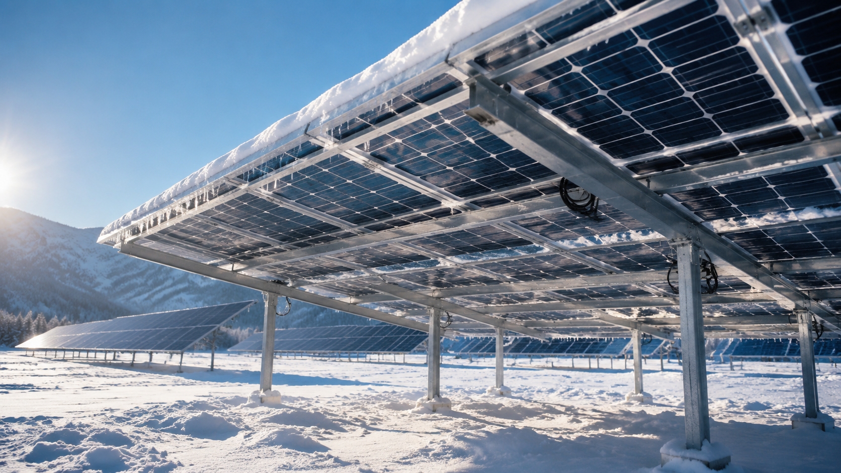
Tilt Angle
Winter-Oriented Tilt Angle
In snowy regions, a steeper tilt generally helps snow slide from the module surface more easily than a low or nearly flat tilt. However, the best winter tilt is not a fixed "latitude plus" rule. It depends on local solar altitude, row spacing, wind exposure, snow type, racking design, ground clearance, and the trade-off between winter yield and annual yield.
A northern Sweden study of frameless bifacial modules at 65°N found that modules mounted at 0° and 15° were covered the most by snow, while 80° and 90° were covered the least. Modules mounted between 25° and 70° showed mostly similar snow coverage and removal behavior. For the full January-to-May test period, modules at 35° to 45° produced the most energy, showing that the steepest angle is not always the best overall energy choice[[4]].
Item | Recommended Approach | Practical Meaning |
Winter tilt selection | Use site-specific simulation and snow-loss modeling instead of a universal fixed formula. | Balances snow shedding, winter irradiation, annual yield, and structural constraints. |
Low-slope roofs | Avoid near-flat installation where repeated snow accumulation is expected. | Reduces prolonged surface snow cover and rear-side shading. |
High-tilt arrays | Check wind load, clamp zones, racking design, and module mechanical-load rating. | Prevents solving a snow-shedding problem while creating a structural risk. |
Tracker systems | Evaluate snow-stow angles and worst-case load conditions when trackers cannot move. | Improves snow management without assuming tracker motion is always available. |
NREL’s PV snow coverage model uses daily snow depth measurements together with hourly system tilt, plane-of-array irradiance, and temperature values. The model treats snow sliding as the dominant removal process, which supports the use of tilt in snow-loss analysis, but it also shows why snow-loss prediction must be location- and system-specific[[5]].
Snow Sliding Path
Snow sliding is affected by tilt angle, module surface condition, lower-edge obstruction, row spacing, and ground clearance. A smooth sliding path helps prevent snow from stopping at the lower edge, melting during daytime, and refreezing into an ice ridge at night.
l Steeper modules usually shed snow more readily than low-tilt modules, but wind, snow type, and temperature can change the actual result.
l Lower-edge obstruction can delay snow release even when the module angle is adequate.
l Ground clearance should be high enough to prevent shed snow from piling up against the lower module edge or blocking rear-side irradiance.
Fresh snow can have very high reflectivity. NASA notes that fresh snow can have an albedo up to about 0.9, meaning it can reflect up to 90% of incoming sunlight[[6]]. IEA PVPS reports a snow albedo range of 0.55 to 0.98 for bifacial PV modeling, depending on snow condition and surface characteristics[[7]]. The design goal is therefore to keep the module glass surface clear while preserving reflected-light access to the rear side.
Snow Condition | Typical Engineering Concern | Risk for Bifacial Panels |
Newly fallen dry snow | Lower density and easier displacement, but still strongly shading. | Can block front irradiance and reduce rear-side contribution if it piles below the array. |
Wind-packed or compacted snow | Higher density and stronger bonding after wind action or settling. | Can increase mechanical load and slow natural shedding. |
Wet snow or refrozen slush | Higher weight and stronger adhesion at edges, clamps, and frame lips. | Can create lower-edge ice ridges that block later snow release. |
Snow density changes quickly with temperature, wind, liquid water content, and compaction. UBC snow-density teaching material notes that freshly fallen snow commonly ranges from about 5% to 20% total water content, which corresponds approximately to 50 to 200kg/m³, before later settlement or compaction[[8]]. For PV structural design, local snow-load codes and project-specific engineering calculations should be used instead of one assumed snow density.
Flat Angle Risks
Flat or very low-tilt bifacial panels face higher winter risk because snow can remain on the glass surface for longer periods. Low ambient temperature can improve silicon module electrical output when the module is clear, but snow and ice shading usually dominate the losses when the active area is covered.
l Low-slope arrays are more likely to experience persistent snow cover after snowfall.
l Snow piles between rows can block rear-side reflected light and reduce bifacial gain.
l Manual snow removal must avoid sharp tools, excessive pressure, and unsafe rooftop access.
The U.S. Department of Energy notes that higher tilt angles help snow shed more quickly, but also increase wind load and cost, so the system designer should find a compromise between snow shedding, solar production, and structural drivers[[9]]. For flat-roof projects, tilted racking should therefore be designed together with roof snow-load management, access paths, and maintenance safety.
Heavy snow regions also require careful module-load verification. The U.S. Department of Energy states that a typical module rating is 2400Pa and recommends selecting modules certified to withstand at least 5000Pa for locations at risk of heavy snow accumulation, while also checking the installation manual for the static snow-load rating of the exact mounting configuration[[9]].
Low-Obstruction Edge Design
Reducing Lower-Edge Obstruction
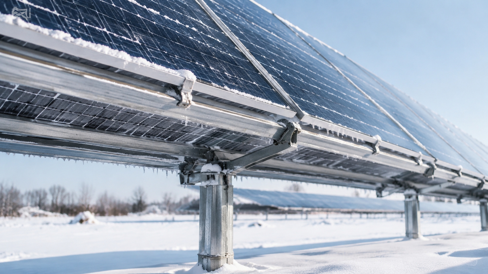
Module edge geometry is important in snowy climates. A raised lower frame can act as a small barrier that holds snow, slush, and meltwater. When temperatures fall again, retained water can refreeze and create a harder ice edge that delays the next snow-shedding event.
Frameless modules or low-profile frame designs can reduce this obstruction. The U.S. Department of Energy states that frameless modules can shed accumulated snow more quickly because a frame can prevent snow at the lower tip of the panel from sliding off after heavy snowfall. The same guidance also warns that frameless modules may have lower snow and wind load ratings, so load rating should take priority over snow-shedding ability[[9]].
Design Type | Winter Weak Point | Ice Prevention Effect |
Conventional framed module | The lower frame lip can retain snow, slush, and meltwater. | Higher chance of lower-edge ice retention if snow cannot slide fully off the panel. |
Frameless module | Requires careful mounting and verified mechanical-load capacity. | Smoother snow exit path and reduced lower-edge obstruction. |
Low-profile framed module | Still has a frame, but with reduced snow-catching geometry. | Can lower snow retention compared with deeper frame lips, depending on installation details. |
A Sandia-led field comparison of adjacent PV systems in Vermont studied otherwise similar framed and frameless modules on a 35° fixed-tilt rack. The study found that the frame affected snow-shedding ability and the related energy loss from reduced snow removal[[10]]. This supports evaluating frame presence and edge geometry as part of snowy-site energy-yield design, not only as a mechanical or appearance feature.
Smooth Snow Exit
A smooth snow exit path reduces the chance that snow will stop at the module edge, densify, and refreeze. This is especially important for bifacial panels because bottom snow piles can also reduce rear irradiance and lower the benefit of high winter albedo.
l Keep the lower edge free from unnecessary lips, cable loops, clamps, clips, and accessories that can catch snow.
l Leave enough clearance below the module for shed snow to fall away instead of pressing against the glass edge.
l Do not use module frames as snow-retention devices; rooftop snow-retention design should be handled separately.
Check whether the selected mounting method changes the module’s permitted snow-load rating.
The U.S. Department of Energy also notes that tilted modules can accumulate snow unevenly at the bottom edge near the frame, creating greater stress on the lower portion of the module[[9]]. For this reason, edge geometry, clamp position, module orientation, and snow-load rating should be reviewed together.
Edge Sealing and Mechanical Reliability
Cold-region PV modules experience combined stress from snow load, wind load, thermal cycling, and repeated wetting and freezing near edges. The main reliability goal is to prevent water retention and mechanical stress concentration around glass edges, frames, clamps, junction boxes, and cable contact points.
For heavy snow sites, module selection should focus on verified mechanical load rating, approved clamp zones, installation-manual compliance, and the ability of the racking system to support non-uniform loads. The U.S. Department of Energy warns that under heavy loads, invisible cracks can form in solar cells, and that heavy snow weight and ice buildup have caused frames to detach from modules in severe winter weather[[9]].
Reliability Check | Why It Matters in Winter | Practical Action |
Static snow-load rating | Snow can accumulate unevenly at the lower edge. | Use the rating for the exact module and mounting configuration. |
Clamp zones and support points | Incorrect clamp positions can increase glass and cell stress. | Follow the approved installation manual and local engineering design. |
Frame or edge profile | Raised edges can retain slush and refrozen meltwater. | Use frameless or low-obstruction edge designs where load rating permits. |
Cable and accessory routing | Cables and clips can catch snow or create local refreezing points. | Route cables away from the lower snow-shedding path. |
Rear Thermal and Optical Management
Rear Airflow and Clearance
Rear-side airflow affects module temperature, drying behavior, and the stability of snow and ice around bifacial modules. Too little clearance can create stagnant zones and slow drying behind the module. Excessively exposed layouts may increase wind load and local drifting. The correct clearance is therefore a site-specific design decision.
The Faiman module temperature model, presented by Sandia’s PV Performance Modeling Collaborative, estimates module temperature using ambient air temperature, plane-of-array irradiance, and wind speed[[11]]. This is directly relevant to winter design because rear airflow and wind exposure influence module temperature and drying behavior, while also affecting structural design loads.
Rear-Side Condition | Winter Impact | Design Response |
Very small rear gap | Restricted airflow and slower drying behind the module. | Increase clearance where roof height, wind load, and racking design allow. |
Open-rack ground mount | Better rear ventilation, but more exposure to wind and drifting snow. | Verify wind load, row spacing, ground clearance, and foundation design. |
Snow pile behind or below module | Rear shading and delayed melting or refreezing cycles. | Use adequate lower-edge height and maintenance access for snow management. |
Uneven rear irradiance | Reduced bifacial gain and possible rear-side mismatch loss. | Model row spacing, mounting height, albedo, and shaded ground zones. |
For heavy snowfall areas, the U.S. Department of Energy recommends elevating the bottom edge of PV systems high enough to accommodate shed snow, while also weighing the cost and increased wind load[[9]]. This is especially important for bifacial arrays because snow piles below the module can shade the rear side even when the front glass is clear.
Rear Heat Loss and Refreezing
Winter bifacial systems operate in a complex thermal environment. Snow-covered ground can increase reflected shortwave irradiance, while cold sky conditions, low ambient temperature, wind exposure, and shaded areas can allow meltwater to refreeze at edges, clamps, cable contact points, and rear-side structures.
l Fresh snow can improve rear-side irradiance through high albedo when the module surface is clear.
l Nighttime cooling and shaded areas can allow meltwater to refreeze near lower edges and mounting hardware.
l Rear clearance and airflow should support drying without creating unsafe wind-load conditions.
l Snow piles between rows should be considered part of both optical and mechanical winter design.
IEA PVPS reports that bifacial system performance is strongly affected by albedo, tilt, pitch, mounting height, row layout, and rear-side irradiance distribution[[7]]. Therefore, rear-side thermal and optical design should be handled together rather than treating the rear side only as a cooling surface.
Shadow Cooling and Rear-Side Shading Risk
Winter shading affects bifacial panels in two ways. First, shaded cells or module areas receive less irradiance and generate less current. Second, shaded snow or ice zones can remain colder for longer, delaying melting and increasing the chance of repeated refreezing.
l Snow mounds between rows can shade the rear side and reduce bifacial gain.
l Adjacent-row shading is more severe when the winter sun angle is low.
l Tracker algorithms should consider winter backtracking, snow-stow angles, row-to-row shading, and snow accumulation patterns.
l Rear-side irradiance should be measured or modeled in projects where bifacial gain is financially important.
IEA PVPS notes that bifacial modeling must account for rear-side irradiance, shading from mounting structures or tracking systems, soiling on the rear side, and mismatch related to rear-side non-uniformity[[7]]. In snowy climates, these effects can become more important because ground albedo, row shadows, and snow piles change quickly after each snowfall.
A 2022 study comparing monofacial and bifacial PV systems in snowy environments found that bifacial modules can perform better in severe winter conditions when rear-side irradiance is available and snow losses are controlled. In that study, average winter snow losses were 33% for the monofacial system and 16% for the bifacial system, with a reported winter bifacial gain of 19% compared with the monofacial system[[12]]. These results should be treated as site-specific evidence, not as a universal guarantee for every snowy project.