What Causes Snail Trails on Photovoltaic Modules
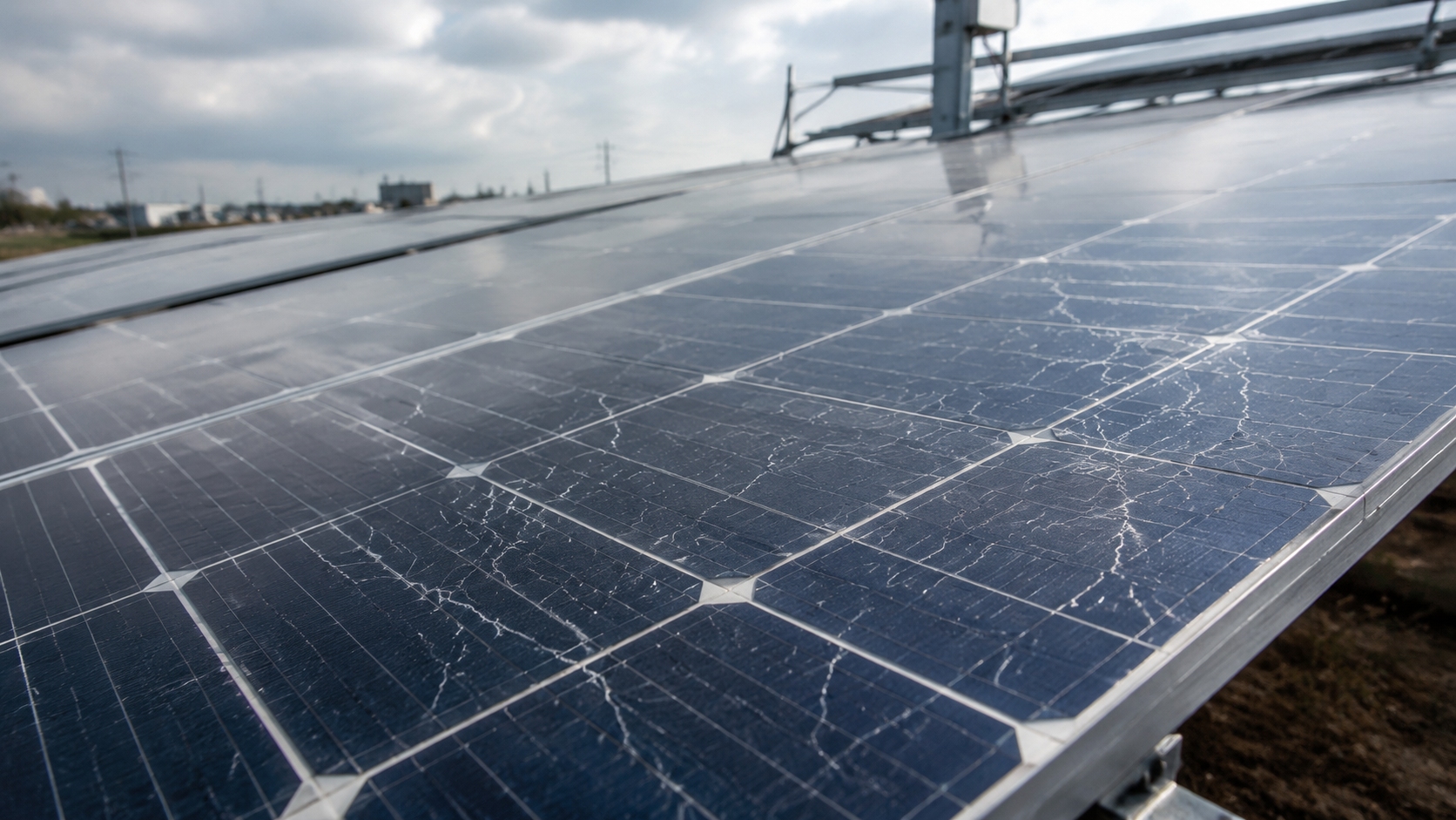
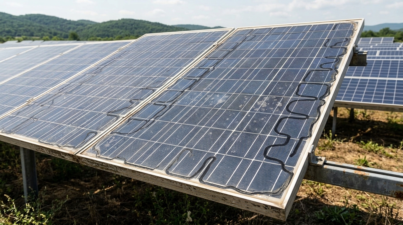
Snail trails—also called snail tracks or worm marks—are visible grey, yellow-brown, or dark discoloration patterns found mainly on crystalline-silicon photovoltaic modules. They commonly follow front-side silver grid fingers, cell edges, or cell-crack paths. IEA PVPS describes a snail track as discoloration of the front metallization and notes that it typically becomes visible approximately three months to one year after installation, although the timing varies among module designs and operating environments.
Snail trails should not be attributed to one cause acting alone. Available evidence links their formation to an interaction among cell cracks or cell-edge pathways, silver metallization, encapsulant and backsheet chemistry, oxygen and other mobile reaction products, ultraviolet exposure, temperature, and the complete module bill of materials.
Key distinction:
the visible discoloration and the underlying electrical defect are not the same. Current IEA PVPS guidance reports that snail tracks themselves have no demonstrated direct influence on module performance. However, an associated cell crack, electrically separated cell region, damaged grid finger, interconnect defect, or another failure may reduce power or create abnormal heating.
How Snail Trails Form
Relationship with cell cracks and cell edges
Snail trails are frequently observed along narrow cell cracks and around cell edges. Small cracks that are invisible under ordinary lighting may become visually apparent after metallization discoloration, encapsulant photobleaching, or local delamination develops along the same path.
Electroluminescence imaging often confirms that a visible trail follows a crack. However, the electrical importance of that crack depends on whether it interrupts current collection, damages grid fingers, or separates a portion of the cell from the electrical circuit. A crack may remain electrically bridged and have limited immediate impact, while a different crack of similar visible length may isolate a substantial active region.
A crack is therefore a common precondition for a crack-aligned snail trail, but it is not sufficient by itself. Many cracked cells never form visible snail trails. IEA PVPS identifies the combination of module materials, UV radiation, and temperature as an important reason why susceptibility differs among modules.
Silver-related discoloration and chemical evidence
Microscopy and chemical studies have linked snail-trail discoloration to changes involving the silver metallization system. Meyer and co-workers identified silver nanoparticles in the encapsulant immediately above affected grid fingers and associated those particles with the characteristic discoloration.
Peng and co-workers identified silver carbonate nanoparticles on discolored silver grids. Other investigations have reported silver acetate, silver phosphate, silver carbonate, and silver sulfide. Silver sulfide was reported in artificially induced damp-heat cases, while the other products have also been identified in field-exposed modules.
Fan and co-workers identified silver acetate and proposed a mechanism involving the silver grid, oxygen, and acetic acid near a microcrack. These findings do not establish one universal chemical pathway. Instead, they indicate that the term "snail trail" can describe visually similar discoloration produced by more than one material interaction.
The roles of oxygen, moisture, EVA, and material transport
Polymeric encapsulants and backsheets are not perfect barriers to gases and volatile compounds. Their composition and transport properties influence the chemical environment around the cells and metallization. In EVA-based modules, degradation can generate acetic acid, which may contribute to corrosion or silver-containing reaction products when suitable transport and environmental conditions are present.
In the model and accelerated tests reported by Fan and co-workers, a microcrack together with a cell gap acted as a transport pathway, and oxygen transmission through the backsheet had an important influence on silver-acetate formation. Within the water-vapor transmission range examined in that study, water-vapor transmission was not found to control snail-trail formation.
This result is important because it shows why the simplified statement "moisture ingress causes snail trails" is incomplete. Humidity can contribute to corrosion, encapsulant degradation, delamination, and other module failures, but the importance of moisture, oxygen, acetic acid, additives, and transport pathways depends on the specific bill of materials and reaction mechanism.
Changing from EVA to a polyolefin-based encapsulant may eliminate the EVA deacetylation route to acetic acid, but it is not a universal guarantee against discoloration or other degradation. Adhesion, additives, lamination conditions, optical stability, electrical properties, adjacent layers, and long-term interface compatibility must still be evaluated as a complete material system.
Frame, backsheet, and junction-box defects
Frame-seal deterioration, backsheet cracking, delamination, and defective or detached junction boxes are important module reliability and safety issues. They may permit humidity ingress, promote corrosion, damage insulation, stress electrical connections, or increase the risk of arcing.
These conditions should not automatically be assigned as the cause of a visible snail trail. A trail near a frame edge or junction box does not prove a particular moisture-entry point. The suspected defect must be confirmed through physical inspection, electrical testing, imaging, and, where necessary, laboratory material analysis.
IEC 62790 establishes construction, safety, and test requirements for junction boxes used with photovoltaic modules up to 1,500 V DC. It does not define a characteristic snail-trail radius, direction, or fan-shaped pattern for junction-box leakage.
Why Cell Cracks Occur
Manufacturing and module assembly
Cell cracks can originate during wafer, cell, and module manufacturing. Potential sources include cell handling, cutting, stringing, soldering, lay-up, lamination, framing, and local mechanical pressure. Repetitive crack patterns across multiple modules may indicate a production-related mechanism, but crack appearance alone does not always establish the exact event that caused the damage.
Packaging, transport, and installation
Packaging failure, transport vibration, impact, unloading, unsupported lifting, frame twisting, incorrect clamp positions, excessive fastening loads, and walking or kneeling on modules can create new cracks or propagate pre-existing ones. IEA PVPS identifies packaging, transport, and installation as major post-production sources of cell cracking.
EL imaging at production, before shipment, at receipt, or after installation can provide evidence about the presence and development of cracks. Comparisons are most useful when imaging conditions, module current, camera setup, orientation, and image processing are controlled.
Environmental and operational loading
After installation, wind, snow, hail, tracker movement, structural deflection, repeated thermomechanical stress, and maintenance activities may create or extend cracks. Some crack patterns can suggest heavy mechanical loading or production-related damage, but IEA PVPS cautions that the final cause of cell breakage is not always easy to identify.
Cleaning should follow the exact module manufacturer's instructions. Abrasive tools, concentrated pressure, standing on modules, lifting by cables, twisting the frame, or any procedure that significantly deflects the laminate should be avoided.
Performance and Safety Impact
Visible discoloration versus electrical damage
Current IEA PVPS guidance states that snail tracks are reported to have no influence on module performance. This statement refers to the visible metallization discoloration itself. It does not mean that every module displaying a snail trail is electrically healthy.
The underlying cell crack or an accompanying defect may reduce performance if it:
l separates an active part of the cell from the electrical circuit;
l interrupts silver grid fingers or cell interconnects;
l creates a high-resistance or unstable electrical path;
l causes current mismatch within a substring;
l develops together with corrosion, delamination, or another failure mode.
For this reason, visible trail length, darkness, or percentage coverage cannot be converted into a universal power-loss equation. Two modules with visually similar trails may have very different EL images, I-V curves, and operating temperatures.
Interpreting published power-loss studies
A frequently cited Italian study examined 31 modules, including 16 modules with visible snail trails and 15 without visible degradation. Four modules from the lower-performing group were selected for outdoor energy comparison. During the monitored period, those four selected modules produced approximately 68%–88% of the energy produced by a damage-free reference module.
Those values should not be treated as the typical loss for all modules with snail trails. The four modules were not a random sample of every affected module: they were selected from modules showing relatively poor electrical performance and contained significant cracks, electrically separated regions, or poor finger contacts. The authors associated the reduced output with microcracks and damaged cell regions rather than with the visible discoloration alone.
The same study also found no clear additional performance decline during its later two-year comparison, despite only minor development of new discoloration. This further supports the need to distinguish the initial cell damage from the subsequent visual evolution of the trail.
Appropriate electrical assessment
For a specific project, performance should be assessed using measured evidence rather than visual appearance alone. Relevant information may include:
l module or string operating current;
l maximum power and fill factor;
l short-circuit current and open-circuit voltage;
l I-V curve shape and resistance-related changes;
l baseline factory flash data;
l matched reference modules;
l historical monitoring data;
l EL evidence of electrically inactive cell regions.
IEC 60904-1 specifies procedures for measuring photovoltaic current-voltage characteristics. IEC 60891 defines procedures for correcting measured I-V characteristics for differences in temperature and irradiance. For bifacial devices, the measurement approach should also reflect the requirements of IEC TS 60904-1-2.
Hot spots, burn marks, and fire-related risk
A visible snail trail does not automatically indicate a hot spot or imminent fire. Thermal risk arises when the associated defect creates an electrically inactive cell region, current mismatch, a high-resistance connection, an interconnect failure, a defective bypass path, or another condition that generates localized heating.
IEA PVPS identifies hot spots and burn marks as possible consequences of inactive cell parts caused by cracking. Separate failures involving connectors, cables, junction boxes, or interconnects can also cause arcing and fire-related hazards. The visible discoloration alone is therefore insufficient to determine safety risk.
Abnormal heating, burn marks, melted polymer, glass damage, arcing evidence, a loose junction box, exposed live parts, severe backsheet damage, or insulation failure require prompt assessment by qualified personnel.
Detection and Diagnosis
Method | Primary Use | Main Limitation |
Visual inspection | Documents discoloration, glass and frame damage, delamination, bubbles, backsheet defects, burn marks, and junction-box condition | Cannot determine whether a crack has electrically isolated active cell area |
Electroluminescence (EL) | Shows cell cracks, electrically inactive regions, finger interruptions, and current-distribution abnormalities | Image appearance depends on applied current, equipment, exposure, focus, processing, and interpretation |
I-V measurement | Quantifies maximum power, current, voltage, fill factor, and curve-shape changes | Requires reliable irradiance and temperature data, correction procedures, and a valid comparison basis |
Infrared thermography | Locates abnormal cell, substring, connector, diode, cable, or junction-box temperatures during operation | Does not by itself reveal the precise crack geometry or chemical cause |
UV fluorescence (UVF) | Shows polymer aging and photobleaching patterns around cracks, cell edges, and material interfaces | Is not a direct quantitative moisture measurement and does not prove a specific snail-trail chemical reaction |
Laboratory material analysis | Identifies silver compounds, corrosion products, polymer composition, additives, and local interfaces | May be destructive, sample-limited, costly, and unsuitable for routine plant-wide screening |
Visual inspection
Visual inspection should document the module identification number, array location, date, weather conditions, viewing side, image scale, trail position, apparent progression, and any nearby cracking, bubbling, delamination, browning, burn marks, or mechanical damage.
Photographs taken from a consistent position under comparable lighting are more useful for trend assessment than isolated images. The inspection should also cover the rear surface, junction box, connectors, cables, frame, clamps, and mounting condition where access is safe.
Electroluminescence imaging
EL is one of the most informative methods for determining whether a visible trail coincides with a cell crack and whether an electrically inactive region is present. IEC TS 60904-13 specifies methods for capturing and processing EL images and gives guidance for qualitative interpretation of observed features.
EL should not be treated as a simple photograph with an automatic pass-or-fail result. Applied forward current, camera sensitivity, exposure, focus, ambient light, module temperature, image normalization, and module architecture can materially affect image appearance.
Dark regions may indicate electrically inactive or poorly conducting areas, but the cause may include cracking, interconnection defects, shunting, finger interruption, or other electrical non-uniformity. Interpretation should therefore consider the visual image, module design, I-V data, and comparison images.
I-V measurement and performance monitoring
I-V measurement is required when the objective is to quantify electrical impact. Useful indicators include maximum power, current at maximum power, fill factor, short-circuit current, open-circuit voltage, and changes in curve shape.
Measurements should be made under suitable conditions and translated to comparable temperature and irradiance conditions using applicable procedures. Comparing uncorrected field measurements from different days can produce misleading conclusions.
Plant monitoring can help identify persistent string-current deviation, abnormal yield, or progressive underperformance. IEC 61724-1 outlines terminology, equipment, and methods for photovoltaic-system performance monitoring and analysis.
String-level monitoring may not isolate one affected module, particularly where multiple modules share an MPPT input. Targeted module-level measurements or controlled substitution may be needed to locate the source of a deviation.
Infrared thermography
Infrared inspection is appropriate for detecting abnormal operating temperatures in cells, substrings, bypass diodes, junction boxes, connectors, and cables. Outdoor PV thermographic inspection is addressed by IEC TS 62446-3.
Thermal images are affected by irradiance, wind, ambient and module temperature, viewing angle, reflections, shading, electrical load, module technology, and recent operating history. A thermal anomaly should therefore be confirmed with electrical measurements, visual inspection, and EL where necessary.
A universal temperature-difference threshold should not be applied without considering the inspection conditions, module construction, operating state, and applicable procedure.
UV fluorescence
UV fluorescence can reveal encapsulant fluorescence and photobleaching patterns associated with aging, oxygen access, cell boundaries, and cracks. It can help compare modules with different bills of materials and identify patterns that may not be apparent under ordinary lighting.
UVF is not a direct quantitative measurement of moisture content. It should not be used to claim that moisture has reached a particular depth, that a specific chemical reaction has occurred, or that a visible snail trail will appear after a predetermined number of months.
Laboratory analysis
Where root-cause allocation is commercially or technically important, laboratory methods may include optical microscopy, scanning or transmission electron microscopy, Raman spectroscopy, elemental analysis, polymer analysis, adhesion testing, and cross-sectional examination.
Laboratory findings should be linked to the exact module construction, exposure history, sampling position, and comparison area. Detecting one silver compound in one sample does not establish that the same mechanism applies to every module displaying similar discoloration.
Prevention and Mitigation
Procurement and qualification
l Verify that the exact module model and relevant bill-of-material variants are covered by valid design-qualification and safety-qualification documentation.
l Review certificate scope and test reports rather than relying only on a certification logo or a general product-family statement.
l Request traceable factory flash-test data, EL records, serial-number traceability, and agreed acceptance criteria for cracks and inactive regions.
l Evaluate the complete material system, including glass, cells, metallization, encapsulant, rear glass or backsheet, adhesives, junction box, and manufacturing process.
l For severe environmental or mechanical conditions, consider extended or sequential testing targeted to the expected project stresses.
l Confirm that changes to critical materials or construction remain within the applicable certification and change-management process.
IEC 61215 provides design-qualification and type-approval requirements for terrestrial photovoltaic modules. The standard expressly notes that qualification results are not a quantitative prediction of module service life, which also depends on design, environment, and operating conditions.
IEC 61730 addresses photovoltaic-module safety qualification, including construction requirements and testing related to electric shock, fire, mechanical, and environmental hazards.
IEC TS 63209-1 provides extended-stress test sequences for comparative evaluation of modules and different bills of materials. IEC TS 63209-2 provides a menu of extended tests for polymeric backsheets and encapsulants. These documents supplement baseline qualification and are intended for reliability analysis rather than as simple universal pass-or-fail lifetime tests.
IEC TS 62915 provides a uniform approach for maintaining type approval, design qualification, and safety qualification when an originally assessed module design is modified.
Manufacturing quality assurance
l Control cell handling, stringing, soldering, ribbon or wire tension, lay-up, lamination, and framing loads.
l Use defined EL inspection conditions and maintain traceable images at agreed production stages.
l Monitor material-lot changes and supplier changes that may alter additives, permeability, adhesion, curing, or interface compatibility.
l Validate the complete laminate rather than assuming that one individually qualified material will remain compatible with every adjacent material.
l Investigate repetitive crack or discoloration patterns at batch level rather than treating each module as an isolated event.
Transport and installation
l Follow the manufacturer's packaging, transport, storage, lifting, clamping, support-spacing, and torque requirements.
l Quarantine pallets or modules showing packaging collapse, impact, frame distortion, broken glass, backsheet damage, loose junction boxes, or cable stress.
l Lift modules only at approved locations and do not carry them by cables or junction boxes.
l Use only approved clamp zones, mounting components, support configurations, and tightening procedures.
l Do not stand, kneel, or place tools or other concentrated loads on the laminate.
l Use pre-shipment, incoming, or post-installation EL sampling where the project risk and contract requirements justify it.
Operation and maintenance
IEC 62446-2 provides preventive, corrective, and performance-related maintenance recommendations for grid-connected photovoltaic systems. Inspection frequency should be based on the environment, failure history, system criticality, warranty requirements, observed defect progression, monitoring results, and safety exposure.
A universal rule such as "inspect every snail-trail module quarterly" is not supported for all sites. A module displaying stable cosmetic discoloration with normal EL, electrical, thermal, insulation, and mechanical findings does not require the same response as a module displaying inactive cell regions, abnormal heating, arcing evidence, or insulation failure.
Recommended diagnostic sequence:
Visual documentation → performance-data review → IR screening under suitable operating conditions → targeted EL imaging → I-V or module-power measurement → qualified electrical-safety or laboratory testing where corrosion, insulation failure, delamination, burn damage, or disputed root cause is suspected.