How Does LeTID Affect Solar Module Lifespan | High Temperatures, Carrier Recombination, N-Type Solutions
LeTID (Light and Elevated Temperature Induced Degradation) is one of the key reliability challenges for solar modules, especially when modules operate for long periods under high irradiance and elevated cell temperature.
Kiwa PVEL's LID and LeTID test procedure places modules in an environmental chamber at 75°C while injecting low current for 324 hours to mimic inverter-connected operation in full sun at maximum power point. Kiwa PVEL also notes that LeTID mainly affects PERC cells and is more severe in hot climates, although it can also occur in temperate regions during hot, high-irradiance periods[1].
This article explains two important reliability pathways — high-temperature stress and carrier recombination — and then looks at N-type cell technology as a lower-risk solution.
l High temperature accelerates material aging, hot spots, solder fatigue, and thermal stress.
l Carrier recombination reduces minority carrier lifetime and appears as measurable power loss.
l N-type technology generally reduces LID and LeTID risk, but it does not remove the need for wafer, hydrogen, firing, passivation, and BOM-level quality control.
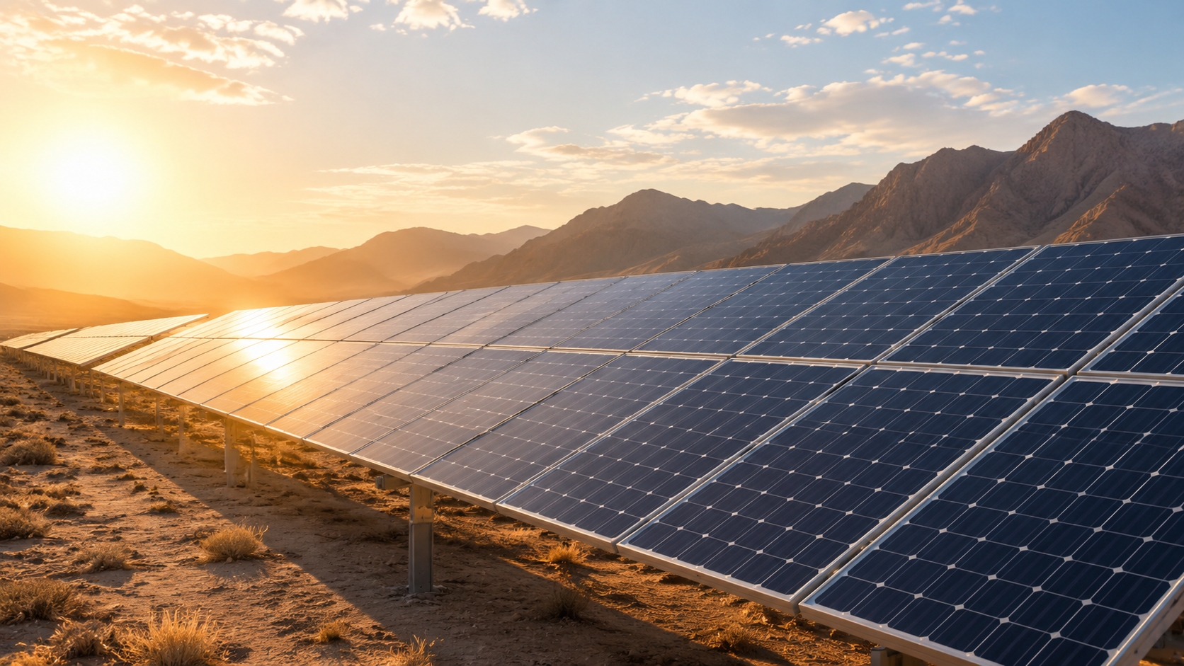
High Temperature
Accelerated Damage Under High Temperature
During field inspections of ground-mounted power plants in Northwest China, our technical team used infrared thermography to check P-type PERC modules after 3 years of operation.
l Junction temperatures at summer noon exceeded 65°C.
l Local hot-spot areas reached around 82°C.
l This high-temperature environment accelerates encapsulant aging, interconnect fatigue, solder-joint stress, and metallization-related reliability risks.
l Contact resistance between ribbons and busbars can increase over time when modules are exposed to repeated thermal cycling and high operating temperature.
l For new high-temperature projects, the N-type TNC module family uses TOPCon cell technology, bifacial double-glass construction, and a low temperature coefficient to reduce lifecycle energy loss.
Temperature control is a key factor in PV lifecycle assessment because many module degradation reactions are accelerated by heat, irradiance, humidity, and thermal cycling.
From a system perspective, high temperature affects the LCOE of PV power plants. IEA PVPS notes that degradation effects and total lifetime directly influence electricity production, cash flow, LCOE, and project profitability. It also emphasizes that real degradation processes in the field are often non-linear and depend on module components, operation, and climate conditions[2].
Project condition | P-type module result | N-type module result |
50MW ground-mounted plant in a high-temperature region with annual average temperature above 25°C | If an additional 1.8% LeTID-related stabilized loss occurs in the first year, the lifetime generation loss from that one-time loss is close to 1.8%. If higher annual degradation is also assumed, the cumulative lifecycle loss becomes larger and must be modeled year by year. | Under the same operating conditions, N-type modules generally show lower LID+LeTID sensitivity and lower annual degradation assumptions, but the exact benefit depends on the tested cell technology, BOM, module design, and project climate. |
In our field experience across China, Australia, and the Middle East, modules installed in open-rack configurations usually operate at lower temperatures than modules on poorly ventilated rooftop structures.
l This temperature difference can reduce the risk of heat-driven degradation in head-to-head comparisons.
l Proper ventilation spacing between the module backsheet or rear glass and the mounting surface helps reduce heat accumulation during peak irradiance hours.
l Our technical team now includes rear-side ventilation checks in standard system design recommendations for high-temperature regions.
l For rooftop projects, increasing rear clearance under narrow-spacing conditions can reduce peak cell temperature and lower thermal stress.
l This provides a low-cost design lever for LeTID and thermal-aging mitigation.
Further reading: PV Module Service Life Estimation, Kiwa PVEL LID+LeTID Test.
Hot Climate Risks
In hot climate zones such as the Middle East and North Africa, solar modules operate at elevated temperatures for long periods.
During technical due diligence for a large Saudi Arabian ground-mounted plant, we observed module rear-side temperatures exceeding 80°C during multiple summer periods. In this type of climate, heat does not act alone; it combines with UV exposure, sand, soiling, humidity variation, and thermal cycling.
l The combined effect of high temperature and strong UV radiation can accelerate encapsulant discoloration and delamination.
l Optical degradation can reduce the light reaching the cell and lower module output.
l Backsheet, encapsulant, edge seal, junction box, frame, and glass-glass construction are important selection criteria for desert projects.
For desert applications, module options are available that emphasize double-glass construction, low degradation, bifacial gain, and high reliability.
Module or solution | Relevant condition | Reliability meaning |
High-temperature utility-scale and C&I applications | The module uses TNC N-type monocrystalline cells and bifacial double-glass construction. Its official datasheet lists a Pmax temperature coefficient of -0.28%/°C[3]. | |
Desert project module selection | High heat, high UV, sand, and frequent cleaning cycles | Bill-of-material selection should focus on glass, encapsulant, edge seal, junction box, frame strength, and verified LID+LeTID/PID test results. |
We have encountered several desert projects in the MENA region where sand accumulation on module surfaces reduced effective irradiance by 8%–12% during dry months.
l This soiling primarily creates a reversible energy-yield loss rather than permanent material degradation.
l Soiling may also change the module thermal profile, but reduced irradiance should not be treated as a LeTID mitigation strategy.
l The net project impact is usually negative because the energy loss from soiling is immediate and measurable.
l Our technical team later developed a cleaning optimization schedule based on real-time soiling rate monitoring.
l This schedule balances water consumption, cleaning cost, and energy recovery.
IEA PVPS defines soiling loss as the reduction in PV electrical output caused by accumulated particles on module surfaces. It also notes that soiling losses vary by site, season, particle type, tilt angle, and cleaning events, so desert projects need site-specific monitoring rather than generic assumptions[4].
Anti-soiling glass and robotic cleaning can reduce soiling-related yield loss when coating durability, cleaning interval, local dust composition, water availability, and O&M cost are verified for the specific site.
Further reading: Soiling Losses in PV Plants, PV Module Service Life Estimation.
Thermal Stress Effects
Differences in the coefficient of thermal expansion (CTE) among module material layers — glass, encapsulant, cells, ribbons, solder joints, frame, and backsheet or rear glass — are the root cause of thermomechanical stress.
Our technical team conducted temperature cycling tests from -40°C to +85°C in our factory aging chamber. The tests revealed micro-cracks at cell edges in a small proportion of samples after 200 cycles.
l These micro-cracks can propagate during outdoor operation.
l They can create electrically inactive areas and, in severe cases, contribute to localized hot spots.
l Accumulated thermal stress can also cause fatigue in ribbons and solder joints.
l IEA PVPS lists cell cracks, disconnected ribbons, burn marks, delamination, EVA discoloration, backsheet failures, and PID among common PV module failure modes[5].
The rate of solder joint fatigue is closely related to temperature cycle amplitude, cycle frequency, interconnect design, soldering process, and laminate mechanical stiffness.
Test or module design factor | Reliability meaning |
IEC 61215 thermal cycling and damp-heat testing | These tests are important screening tools, but they do not fully reproduce every long-term field failure mode. Field climate, BOM selection, and mechanical loading still need separate risk evaluation. |
Multi-busbar and optimized interconnect design | Better current collection and stress distribution can help reduce cell stress concentration and improve resistance to thermal and mechanical fatigue. |
In our experience, the interaction between CTE mismatch and frame stiffness is often underestimated in module reliability assessments.
l Aluminum frames with inadequate torsional rigidity allow greater laminate flexing during thermal cycling and wind loading.
l This can accelerate solder joint fatigue and micro-crack propagation.
l Modules with stronger frame profiles and better laminate support generally show lower micro-crack risk under combined thermal and mechanical stress.
l Our technical team now specifies minimum frame height and thickness requirements for modules used in continental climates where diurnal temperature swings exceed 40°C.
l Public reliability reports indicate that combined climatic and mechanical stress can shorten useful module life if BOM design and installation conditions are not properly matched.
Further reading: Review of PV Module Failures, PV Module Service Life Estimation.
Carrier Recombination
Carrier Lifetime Loss
LeTID is closely related to recombination-active defects in the silicon cell. However, it should not be confused with classic boron-oxygen light-induced degradation (BO-LID).
In boron-doped P-type silicon, boron-oxygen complexes are a primary cause of BO-LID. LeTID is different: it is generally associated with elevated temperature, light or injection conditions, hydrogen-related defect behavior, wafer quality, dopant type, firing process, and passivation stability. Research reviews note that LeTID is an important degradation issue for PERC solar cells and can occur in different silicon wafer types, although its severity depends strongly on material and process conditions[6].
Wafer quality control is the first line of defense against recombination-related degradation.
Our technical team compared initial minority carrier lifetime distributions across different wafer suppliers. Wafers with higher initial lifetime generally showed lower recombination loss after LeTID-oriented aging tests.
In procurement evaluation, our technical team conducts incoming silicon material inspection for every batch to qualify supplier grades.
Incoming minority carrier lifetime standard | Observed LeTID-related risk | Result |
800 μs | Higher failure rate in accelerated screening | Baseline level |
1200 μs | Lower failure rate in accelerated screening | Improved recombination stability |
This correlation has made minority carrier lifetime one of the key incoming inspection thresholds alongside resistivity, oxygen content, and impurity control.
In our experience, the relationship between initial minority carrier lifetime and LeTID resistance follows a diminishing-returns pattern.
l Improving wafer lifetime from a low baseline can significantly reduce stabilized recombination loss.
l After a certain threshold, further lifetime improvement brings smaller marginal reliability gains.
l This helps our technical team optimize wafer procurement cost versus quality for different project types.
l Czochralski-grown wafers with optimized pulling speed, oxygen control, and post-growth treatment can show better stabilized lifetime than standard wafers from the same ingot class.
l For high-temperature projects, wafer oxygen, dopant strategy, hydrogen control, and firing process should be evaluated together rather than as isolated parameters.
Further reading: Research Progress of LeTID, NREL LETID in Legacy and Modern PV Modules.
Defect Traps
Metal impurities such as Fe, Cu, and Ni, together with crystal defects such as dislocations and grain boundaries, can act as traps for carrier recombination.
Under combined high light intensity and high temperature, these recombination-active defects can increase minority carrier capture and reduce effective carrier lifetime.
l High impurity concentration increases the probability of recombination-related power loss.
l High-purity wafer selection, gettering, hydrogen management, and passivation control are all important for reducing defect activity.
l Switching to N-type silicon substrates can reduce sensitivity to some P-type degradation pathways, but it does not remove the need for strict wafer and process control.
The cell production line performs incoming wafer inspection that combines lifetime testing, resistivity control, impurity screening, and PL imaging.
In procurement audits, wafer batches with excessive metal impurity content or localized defect clusters are placed on hold for supplier review before requalification.
Tongwei cell technology includes minority carrier lifetime as an important inspection item in incoming wafer quality control.
In our experience, the spatial distribution of metal impurities within the wafer is as important as their absolute bulk concentration.
l We have encountered cases where a wafer batch passed bulk chemical screening but failed photoluminescence (PL) imaging due to localized Fe-rich clusters near wafer edges.
l These edge clusters act as high-recombination zones.
l They can affect the active cell area during high-temperature process steps and reduce fill factor.
l Our technical team later implemented a dual-screening protocol combining bulk impurity screening with PL imaging for incoming batches.
l This reduced downstream wafer-related rejection and improved module efficiency binning consistency across the production line.
l Recent LeTID research on commercial N-type TOPCon cells identifies hydrogen content, annealing or firing temperature, doping strategy, initial efficiency, wafer quality, and oxidation degree as important impact parameters[7].
Further reading: LeTID in Commercial N-type TOPCon Cells.
Power Output Reduction
Carrier recombination directly appears as power loss.
Under standard test conditions — 25°C, AM1.5 spectrum, and 1000W/m² irradiance — LeTID-sensitive P-type modules can show several-percent power loss after accelerated or field exposure. NREL has shown that LeTID affects minority carrier lifetime and module performance, while degradation and regeneration behavior vary with technology, injection condition, and field temperature profile[8].
For investors, degradation is not only a technical risk. It directly affects project IRR.
For a one-time permanent power loss, each additional 1% of power degradation usually translates to approximately 1% lifetime generation loss. If degradation continues year after year, the cumulative loss becomes larger and must be calculated with a degradation curve.
Project parameter | Value |
Plant size | 100MW ground-mounted plant |
Feed-in tariff | US$0.04/kWh |
Annual equivalent full-load hours | 1500 hours |
First-year revenue | Approximately US$6 million |
Additional 2% LeTID-induced degradation | Approximately US$60,000–US$120,000 in first-year loss, depending on whether the 2% loss is averaged across the year or treated as a full-year stabilized loss. |
Cumulative 25-year impact | Depending on discount rate, degradation timing, and recovery assumptions, the 25-year net present value impact can exceed US$1.1 million. On an undiscounted basis, the gross revenue impact may be higher. |
NREL utility-scale PV modeling treats degradation rate, capacity factor, inverter losses, bifaciality, shading, downtime, and inverter loading ratio as separate system-modeling factors. Its 2024 utility-scale PV baseline incorporates an assumed 0.7%/year degradation rate, while future improvement scenarios model lower degradation rates[9].
In our experience, a 2%–4% STC power loss usually translates into a comparable energy-yield loss. In hot and high-irradiance sites, the financial impact can be amplified by project-specific operating conditions, clipping behavior, curtailment, and seasonal irradiance distribution.
l Project sites with a high DC/AC ratio above 1.3 should model LeTID, clipping, thermal derating, and inverter loading separately.
l A high DC/AC ratio does not directly cause LeTID, but it can change how degradation appears in AC energy output and revenue modeling.
l Our technical team's economic modeling of a 200MW plant in West Texas showed that specifying N-type modules with lower first-year and annual degradation assumptions improved project IRR.
l The value uplift came from lower degradation, better high-temperature performance, and higher lifecycle generation, rather than from LeTID resistance alone.
l This is why degradation assumptions should be validated by product qualification tests, warranty terms, and climate-specific energy-yield simulations.
Further reading: NREL LETID in Legacy and Modern PV Modules, NREL Utility-Scale PV ATB.

N-Type Solutions
Reducing LeTID Risk
N-type wafers are not boron-doped as the base material, so they avoid classic BO-LID associated with boron-doped P-type silicon. However, N-type cells can still contain boron-diffused regions depending on the cell structure, and N-type TOPCon can still show LeTID under certain material and process conditions.
IEA PVPS reports that modules containing N-type TOPCon cells are substantially less susceptible to LeTID than early P-doped PERC cells. It also notes that LeTID mitigation is linked to hydrogen diffusion, bulk defect formation, firing process optimization, wafer thickness, and impurity control[10].
Our technical team conducted an 18-month outdoor comparison of TNC TOPCon N-type modules against equivalent P-type PERC modules under identical tilt and irradiance conditions.
Module type | First-year power degradation | Application value |
TNC TOPCon N-type modules | Approximately 0.4% in the monitored comparison | Suitable for high-temperature and high-irradiance regions when verified by BOM-level testing. |
Equivalent P-type PERC modules | Approximately 1.2%–1.8% in the monitored comparison | Higher LID and LeTID risk under the same operating conditions. |
The LeTID resistance advantage of N-type technology makes it particularly suitable for large-scale PV plants in high-temperature, high-irradiance regions such as the Middle East, Australia, and North Africa.
Our technical team's 18-month data further shows that TNC modules had smaller monthly degradation fluctuations during summer months from June to August. P-type PERC modules showed larger seasonal fluctuation, which is consistent with stronger temperature-related degradation and recovery behavior.
The TWMNH-66QD module, as part of the TNC series, is designed for low degradation and long-term energy yield.
In our experience, the N-type advantage becomes stronger under combined stress conditions that are typical of real-world operation.
l N-type TNC modules subjected to combined stress testing showed lower power degradation than equivalent P-type PERC modules under the same internal test conditions.
l This difference is related to wafer base type, passivation structure, hydrogen behavior, and process optimization.
l The TOPCon poly-Si/SiOx tunnel-oxide structure helps maintain passivation quality under thermal and electrical stress when the process is well controlled.
l Third-party test programs also show that recent module BOMs have made significant progress in LID+LeTID performance.
l Kiwa PVEL's 2024 scorecard reported 0.43% median and 0.4% average degradation when combining the average LID and average LeTID value for each BOM produced in 2023. It also reported that 96% of tested BOMs had less than 1% power loss in this test[11].
l These results support the bankability of well-qualified modern N-type products, while still requiring BOM-specific test verification.
Further reading: IEA PVPS Degradation and Failure Modes in New PV Technologies, Kiwa PVEL 2024 LID+LeTID Scorecard.
Superior Thermal Stability
N-type TOPCon modules typically have a lower absolute Pmax temperature coefficient than conventional P-type PERC modules. The N-type bifacial module datasheet lists a Pmax temperature coefficient of -0.28%/°C[12].
This means N-type modules experience less power loss as cell temperature rises above the STC reference temperature of 25°C.
l In our field database, TNC modules showed an average generation gain during summer noon hours compared with P-type PERC modules under similar operating conditions.
l The gain comes from a combination of lower temperature coefficient, lower degradation, bifacial response, and module electrical design.
The temperature coefficient advantage is most important in hot operating conditions.
Field condition | Correct interpretation | System design meaning |
High-temperature summer noon operation | A lower absolute temperature coefficient reduces power loss as cell temperature rises above 25°C. | N-type modules usually have stronger high-temperature energy-yield performance. |
Cold winter noon operation | Low temperature increases output for both P-type and N-type modules. Temperature coefficient alone does not prove N-type superiority in cold conditions. | If N-type outperforms in cold sites, the reason should also include bifacial gain, irradiance, low-light response, actual cell temperature, and electrical design. |
N-type's superior thermal stability can translate into measurable generation advantage across full-year operation, especially in hot and high-irradiance climates.
In our experience, the temperature coefficient advantage of N-type modules creates measurable yield gains even in moderate climates such as Southern Europe.
l For a 50MW plant in southern Spain with 1650 kWh/kWp annual irradiance, a 0.06%/°C coefficient differential can yield tens of GWh of additional generation over a 25-year project horizon, depending on hourly module temperature distribution.
l This advantage is most pronounced during summer months from June to August.
l At monitored field sites, N-type modules consistently outperform P-type modules in daily specific yield during high-temperature months.
l Public research reports indicate that TOPCon and other new cell structures can improve performance, but reliability must still be evaluated through technology-specific degradation and failure-mode testing.
l Thermal stability also reduces the risk of inverter or module-level power-electronics thermal derating when these devices are exposed to high ambient temperature.
Further reading: TWMNH-66HD Datasheet, IEA PVPS New PV Technology Reliability Report.
Longer Module Lifespan
Combining low degradation rates, excellent thermal stability, and strong resistance to combined aging factors such as LeTID, PID, UV, thermal cycling, and humidity stress, N-type modules can offer a significant full-lifecycle generation advantage.
Our 25-year generation simulation shows that TNC technology can deliver approximately 4.5%–6.2% cumulative generation gain over equivalent P-type PERC modules, depending on climate, degradation curve, bifacial gain, temperature profile, and system design. This can reduce LCOE when the higher module value is not offset by procurement cost.
This explains why major global PV investors increasingly evaluate N-type modules in large-scale plant tenders. As noted in the PV module selection guide, module selection should consider power, degradation, temperature coefficient, warranty, and project climate together.
Warranty or field-performance reference | Relevant value |
TNC double-glass modules | 30-year power warranty: first-year degradation within 1%, annual degradation from year 2 to year 30 within 0.4%, and year-30 output not less than 87.4%. |
TNC QD modules | 30-year power warranty: first-year degradation within 1%, annual degradation from year 2 to year 30 within 0.35%, and year-30 output not less than 88.85%. |
Industry modeling reference | NREL utility-scale PV modeling uses 0.7%/year as a baseline degradation assumption, while premium N-type projects may use lower validated assumptions when supported by test data, warranty terms, and field evidence. |
The latest limited warranty document lists the TNC double-glass and TNC QD degradation warranties above, while also distinguishing TPC, TNC, and THC product families[13].
In our experience, project-finance lenders increasingly require independent technical due diligence on module degradation assumptions before committing to non-recourse debt.
l Some utility-scale tenders now explicitly evaluate N-type technology because of lower degradation, better temperature coefficient, and stronger lifecycle energy-yield assumptions.
l LeTID and PID risk remain important technology selection drivers, but they should be assessed using BOM-level test reports rather than cell-type labels alone.
l Actual field degradation rates around 0.35%–0.45% per year are generally close to the 0.4% annual warranty assumption, with some projects below and some slightly above.
l This supports the bankability case for N-type procurement when field data, factory quality control, and third-party testing align.
Further reading: Tongwei Solar PV Module Limited Warranty, NREL Utility-Scale PV Modeling Assumptions.