Large vs. Small Solar Panels | How to you Choose
The 400W large panel has a voltage exceeding 40V, requires an MPPT controller, and is suitable for large-area laying to reduce costs;
The 100W small panel is only one meter long, charges 12V batteries directly, can be installed by a single person in narrow spaces on RVs, and flexibly utilizes fragmented space.
Space
Standard residential modules (usually 120 half-cut cells) are approximately 1.75m x 1.04m in size, while commercial large-format modules (144 half-cut cells) generally exceed 2.2 meters in length.
For structurally complex roofs, large modules are difficult to utilize on roof edges or irregular angled areas due to physical size limitations.
According to the International Fire Code (IFC), a fire access pathway of 91 cm (3 feet) must be reserved on both sides of the roof ridge.
Within such restricted geometric spaces, using smaller modules often allows for an additional row of layout, ultimately making the total system capacity 15% to 20% higher than using single high-power large modules.
Dimension Adaptability
Limitations on Vertical Row Layout
The slope length (distance from ridge to eave) of most residential roofs is fixed. This determines how many rows of solar panels you can lay in this direction.
· Standard Module Data: Length is usually between 1722mm and 1762mm.
· Large Module Data: Length is usually between 2,250mm and 2,384mm.
Assume a typical American suburban home with a south-facing slope vertical length of 4.8 meters (about 15.7 feet).
1. Using Standard Modules:
The length occupied by two rows in portrait orientation is: 1.76m x 2 = 3.52m.
Adding the mid-clamp gap between modules (usually 20 mm) and the reserved space at the top and bottom edges, this fits perfectly within the 4.8-meter range and can easily meet the 91 cm (3 feet) setback distance required for fire access.
2. Using Large Modules:
The length occupied by two rows in portrait orientation is: 2.28m x 2 = 4.56m.
At this point, only 0.24 meters of margin remains on the roof. This not only fails to meet the usually required roof ridge fire channel (0.91 meters) but may even cause rainwater to overshoot the gutter when it rains.
In this scenario with a 4.8-meter slope length, if you forcibly use large modules, you can only install one row.
Whereas with standard modules, you can easily install two rows.
Even if the large module has a single power of up to 550W, one row only provides 550W per column;
Standard modules, although 400W individually, can provide 800W per column with two rows.
Fill Rate of Triangular Areas
Many modern houses adopt a Hip Roof design, which forms a large number of triangular or trapezoidal roof areas.
In these areas, rectangular solar panels are difficult to fill perfectly.
The larger the module size, the coarser this "granularity" becomes, and the more severe the waste of gaps.
We can imagine this as filling a triangle with LEGO bricks:
· Smaller bricks (Standard Modules): The jagged edges are closer to the hypotenuse of the triangle, allowing them to fit into narrower positions near the top of the ridge.
· Larger bricks (Large Modules): The jagged edges are very abrupt.
Data Simulation:
On a triangular roof surface with a base width of 6 meters and a height of 4 meters:
· Large Modules (2.3m x 1.13m): Often can only install one row at the bottom, possibly accommodating only 2 to 3 panels.
· Standard Modules (1.75m x 1.04m): Usually can be arranged in a pyramid shape. 3 panels at the bottom, 2 in the middle, and even 1 more panel (landscape or portrait) can be squeezed in at the top. The total quantity can reach 5 to 6 panels.
Rail Span and Cost
The rails of the mounting system are usually fixed laterally to the roof rafters.
The physical dimensions of the module determine the spacing and stress conditions of the rails.
Clamping Zones Limitations:
Manufacturers have strict regulations on the mounting points of modules, usually requiring clamps to be located at 20% to 25% of the long side of the module.
· For 1.7-meter modules, the spacing between two rails is approximately 1.0 meter to 1.2 meters. This usually disperses wind pressure and snow load well.
· For 2.3-meter modules, the spacing between two rails may need to be increased to 1.4 meters to 1.6 meters.
Snow Load Risk:
In areas with heavy snowfall, if the rail spacing is too large, the risk of deflection in the middle belly of large-sized modules increases significantly.
To prevent glass breakage or frame bending, installers must usually add a third rail for large-sized modules.
· Cost Increase: Adding a third rail directly increases the material cost of the bracket by 50%.
· Increased Penetration Points: More holes need to be drilled in the roof to fix the third rail, increasing potential water leakage risk points.
Standard size modules usually only need two rails with standard spacing to meet most wind and snow load codes (such as 5400Pa) without extra reinforcement costs.
Single-Person Handling and Installation Efficiency
Besides static adaptability on the roof, size also determines the adaptability of the "installation process". This directly affects Labor Cost and installation quality.
Ergonomic Data:
The average wingspan of an adult male is about 1.75 meters.
· Standard Module (width ~1.04m, weight ~20-22kg): Installers can grip both sides of the module relatively firmly with open arms, or move it on a ladder by carrying it on their back alone.
· Large Module (width ~1.13m, length 2.3m, weight ~28-33kg): The physical dimensions exceed the wingspan control range of most people. Although the weight increase seems small (about 10 kg), on a slanted roof, the moment effect makes this 10 kg feel like 20 kg.
Sail Effect:
When working on the roof, if a breeze blows:
· The standard module surface area is about 1.8 square meters.
· The large module surface area is about 2.6 square meters.
The wind-receiving area of the large board increases by 44%.
Obstacle Avoidance
Big Trouble from Small Pipes
The most common obstacle on a roof is the ABS plastic vent pipe with a diameter of about 7.5 cm to 10 cm (3-4 inches).
When you use commercial large modules (size about 2.3m x 1.13m), the cost of encountering a vent pipe is very high:
· Assume a vent pipe is located exactly in the center of the planned installation position.
· Since holes cannot be drilled in tempered glass, you must give up installing the entire module.
· To avoid a small pipe with a diameter of 10 cm, you directly lose 2.6 square meters of power generation area and 550 W of potential power.
In contrast, standard size modules (size about 1.75m x 1.04m) offer finer grid resolution:
· The shorter board length allows you to leave space above or below the vent pipe to install the module without having to leave a large area completely empty.
· Even if installation must be abandoned, the loss is only 1.8 square meters and 400W.
· In the case of multiple vent pipes scattered around, small-sized modules act like smaller floor tiles, making it easier to intersperse among these obstacles to form a continuous array.
Dead Zones Around Skylights
Skylights are usually huge rectangular obstacles, with common sizes of 0.6m x 1.2m.
They typically require at least 15 cm to 30 cm of flashing maintenance space reserved around them according to codes.
When arranging arrays around skylights, the width of the module is a hard constraint:
· Large Module Width: About 1,134mm.
· Standard Module Width: About 1,040mm or narrower.
This 94mm (nearly 10cm) difference often becomes the watershed of "can install vs. cannot install" in actual layout. Assume the distance from the left side of the skylight to the roof edge is 2.3 meters:
1. Large Module Scheme: Installing two large boards side by side requires 1.134 + 1.134 + 0.02 (mid-clamp) = 2.288 meters. This leaves only a 1.2 cm margin at the edge, making construction almost impossible. Installers will usually cut one column directly to avoid risk, halving the capacity in that area.
2. Standard Module Scheme: Installing two standard boards side by side requires 1.04 + 1.04 + 0.02 = 2.1 meters. This will leave a comfortable operating space of 20 cm, allowing two columns to be installed without pressure.
Electrical Accounting of Shadow Shading
Chimneys are typical "shadow machines". This involves the internal circuit structure of the module—Bypass Diodes.
Most crystalline silicon modules have cell strings divided into 3 independent sub-strings by 3 diodes:
· Large Modules (72/144 cells): The physical length is long, and each sub-string covers a longer area. If the shadow of the chimney only covers the bottom row of cells of the module, since the sub-strings of the large board run through a very long vertical distance, this may cause 1/3 or more of the entire large board to be bypassed and stop working.
· Standard Modules (60/120 cells): Small physical size, more compact partitioning. With the same shadow length, it might cover two sub-strings for a large board, but for a small board, it might only affect one sub-string, or the most heavily shaded area can be completely avoided by adjusting the landscape vs. portrait orientation of the small board.
Relocation Costs vs. Construction Compromise
In some extreme cases, to install solar panels, owners will consider moving obstacles on the roof.
· Cost Data: In the United States, the cost of hiring a professional plumber to reroute a roof vent pipe is usually between $300 and $600, depending on attic accessibility.
· Decision Logic: If you spend $500 moving a pipe just to install a 550W large board, it is economically completely upside down.
Total Installed Capacity Comparison
The Mathematical Trap of Efficiency vs. Area
First, a myth needs to be broken: large-sized modules do not necessarily have higher photoelectric conversion efficiency.
Commercial large boards have high power simply because their physical area is large.
Let's look at a typical set of specification data comparisons:
· Model A (Standard Residential): Power 410W, size 1.72m x 1.13m, area approx. 1.94 sq.m.
o Power density per sq.m.: 410 ÷ 1.94 ≈ 211 Watts/sq.m
· Model B (Commercial Large): Power 550W, size 2.28m x 1.13m, area approx. 2.58 sq.m.
o Power density per sq.m.: 550 ÷ 2.58 ≈ 213 Watts/sq.m
Even many high-end residential modules (using N-type TOPCon or HJT technology) have efficiency per square meter that surpasses ordinary commercial modules.
Therefore, if roof shape limitations cause you to install 2 square meters less area with large boards than with small boards, your total installed capacity will suffer a real loss of over 400W.
In limited space, area utilization rate is far more important than the nominal number on a single board.
Filling Game on Trapezoidal Roofs
The vast majority of detached house roofs contain trapezoidal or triangular sections.
This is where small-sized modules shine. We can compare it to filling a jar with stones: large stones leave huge gaps, while gravel can fill more space.
Case Simulation: A Typical Trapezoidal Roof Surface
Assume the roof surface has a bottom width of 8 meters, a top width of 4 meters, and a height of 4 meters (trapezoidal area 24 sq.m).
1. Large Module Scheme (2.3m high):
Due to height limitations, you can only install one row of vertical modules at the bottom. Although the width allows for six panels, the second row cannot fit because the roof narrows and the large boards are too tall.
o Result: 6 panels × 550W = 3.3 kW.
o A large amount of top space remains idle.
2. Standard Module Scheme (1.7m high):
The shorter height allows you to easily arrange two rows. The first row fits 7 panels at the bottom, and the second row fits 4 panels at the top.
o Result: 11 panels × 400 W = 4.4 kW.
o Capacity Increase: +33%.
Series Voltage and Startup Threshold
Inverters have a hard indicator called Start-up Voltage, usually 80V to 120V, while the optimal operating voltage range (MPPT Range) is often higher.
· Voltage Shortcoming of Large Modules: To reduce internal losses, 550W-class large modules are usually designed as "high current, low voltage". Their operating voltage (Vmp) may be only around 31V. If you can only fit four large boards on a small roof orientation, the total voltage is only 124 V.
· Voltage Advantage of Standard Modules: Residential 400W modules typically have an operating voltage between 34V and 40V. If the same roof area fits six small boards, the total voltage can easily reach over 200V.
Microinverter Ratio Limitations
If you are using a microinverter system (such as the Enphase IQ8 series), large modules often encounter hidden capacity waste caused by "Clipping".
The output power of a microinverter is capped. For example, the continuous maximum output of a mainstream microinverter is 384W (AC).
· Paired with 550W Large Board: 550W (DC) / 384W (AC), the DC/AC ratio is as high as 1.43. At sunny noon, all energy generated by the module exceeding 384W is "clipped" and wasted as heat. You bought a 550W board but can only use the 384W peak.
· Paired with 400W Standard Board: 400W (DC) / 384W (AC), the ratio is about 1.04.
Cumulative Loss of Physical Gaps
Mid-clamps are required between every two modules, usually occupying 2 cm of width.
· Large Module Array: Since the span of a single board is large, for the same total roof width, fewer columns are needed, so is the sum of gaps less? It looks like that, but the problem is that large boards often cannot make up a whole number.
· Margin Waste: If the roof is 5 meters wide.
o Large board (width 1.13 m): 4 panels require 4.58 meters. The remaining 42 cm cannot be utilized.
o Small board (width 1.04 m): Due to the small size, perhaps they can be installed horizontally (Landscape), or mixed.
Output Power
Large modules typically have a single panel power between 350W and 550W, mostly using 60-cell, 72-cell, or 144-cell half-cut structures.
Their operating voltage (Vmp) is often higher than 30V, adapting to 24V or 48V cell systems and MPPT controllers.
Small modules range from 10W to 200W, usually composed of 32 or 36 cells, with an operating voltage of about 18V, natively supporting 12V cell charging.
When building a 1,000W system, large modules require only 2 to 3 panels, while small modules require more than 10.
Choosing large modules can reduce the amount of bracket installation and wiring terminals by 70%, lowering the line failure rate.
Power and Cell Specifications
Number of Cells Determines Voltage
The output power of a solar panel is not created out of thin air; it is determined by the number of silicon solar cells connected in series internally and the power generation capacity of a single cell.
A single silicon cell (whether monocrystalline or polycrystalline) generates a voltage of about 0.5 volts to 0.6 volts under standard test conditions.
To obtain useful voltage, manufacturers connect these cells in series like dry batteries.
· 32 or 36 Cells (Small Panel Standard):
This is the "native" specification for 12V systems. The Open Circuit Voltage (Voc) generated by 36 cells in series is about 21V to 22V, and the Maximum Power Voltage (Vmp) is between 17V and 18V.
This voltage setting is very particular. Fully charging a 12V lead-acid cell requires about 14.4V. Although 18V seems a lot higher, the voltage of solar panels drops at high temperatures. These extra 3V to 4V are to ensure that the panel still has enough pressure difference to push current into the cell in hot summer. The power of such panels is usually limited to between 10W and 200W, with smaller size and poorer rigidity.
· 60 Cells (Old Large Panel Standard):
This specification used to be the mainstream for residential roofs. The Vmp generated by 60 cells in series is about 30V to 32V.
Note that this voltage is very awkward. It is too high to charge a 12V cell directly; it is too low to fully charge a 24V cell bank.
· 72 Cells (Standard Commercial/Large Panel):
This is the basic architecture of current high-power panels (above 350W). 72 cells in series provide a Vmp of about 36V to 40V, and Voc can reach over 45V.
This high voltage is not only suitable for 24V systems (leaving ample voltage margin), but in grid-tied systems, high voltage means smaller current for the same power, allowing thinner wires to transmit over longer distances.
Changes Brought by Half-Cut Technology
In the past three years, the 400W, 450W, or even 550W panels you see on the market rarely use 72 complete cells directly, but instead adopt 120 or 144 Half-Cut Cells.
This is a process improvement to increase power density. Manufacturers use lasers to cut standard cells into two.
1. Reduced Resistance: Current is proportional to the area of the cell. After cutting into two halves, the current passing through each half is halved. According to physical laws, internal resistance loss is reduced by 75%.
2. Shadow Shading Performance: Traditional 72-cell panels are usually divided into 3 bypass diode zones. If the bottom is shaded by trees, the entire board may stop generating electricity. The 144-cell half-cut panel is electrically divided into two independent circuits: "upper half" and "lower half". If the lower half is shaded, the upper half can still output at full speed with 50% power.
Silicon Wafers Got Bigger
In addition to the slicing method, the physical size of the cell itself is also increasing, which directly pushes up the wattage and current of a single panel.
Early panels used M2 (156.75mm) silicon wafers, later developing to M6 (166mm).
Currently, mainstream high-power panels use M10 (182mm) or G12 (210mm) silicon wafers.
· Current Shock:
Panels using G12 large silicon wafers may have a Short Circuit Current (Isc) as high as 18 Amps or even 20 Amps.
Most standard MC4 terminals are rated for 20A or 30A. If you connect two such high-current panels in parallel, the total current may exceed 35A, which will melt standard 10 AWG PV cables and ordinary connectors.
· Selection Warning:
When purchasing ultra-high power panels over 500W, you must check whether your charge controller supports such high input current (Isc) and whether your combiner box fuse matches. Small 100W panels usually have a current of only 5A to 6A, so there is almost no need to worry about this problem.
Voltage Matching in Actual Applications
After understanding cell specifications, voltage matching is required during system design.
1. 12V Cell System:
o Best Match: 12V nominal panel (36 cells). Direct connection is simple, PWM controller cost is low.
o High Power Solution: Use a 400W large panel (144 half-cut cells, equivalent to 72-cell specs), combined with an MPPT controller. The controller will convert the panel's 40V voltage to 14.4V while amplifying the current by nearly 3 times to charge the cell.
2. 24V Cell System:
o Pitfall Guide: Try to avoid using single 60-cell or 120-cell half-cut panels. As mentioned earlier, their 30V operating voltage will drop to 26V-27V in summer heat, failing to fully charge a 24V cell bank.
o Recommended Solution: Use 72-cell (or 144 half-cut) panels, or connect two 12V panels (36 cells) in series.
3. 48V Cell System:
o This is the standard for large off-grid energy storage.
o Series configuration must be used. Usually, 2 or 3 large panels need to be connected in series to make the array total voltage reach 70V to 150V, and then step-down charging is performed through a high-voltage MPPT controller. Under this configuration, the greater the power of a single panel (e.g., choosing 550W instead of 300W), the easier it is to control the total voltage after series connection within a safe range (e.g., below 150V) while obtaining extremely high total power.
Voltage Parameter Differences
Understanding Voltage Numbers on Labels
When you flip the solar panel and check the specification label on the back, you will see two data points regarding voltage: Open Circuit Voltage (Voc) and Maximum Power Voltage (Vmp).
These two numbers exhibit completely different logic on large and small panels, directly determining the complexity of your power distribution system.
For small panels, Vmp is generally set between 17V and 18V.
· Why so much higher than 12V? A standard 12V lead-acid cell needs to reach about 14.4V when fully charged, and if it is a Lithium Iron Phosphate cell (LiFePO4), it needs 14.6V.
· In addition, a margin of 2V to 3V must be reserved to offset the Voltage Drop passing through wires, fuses, and connectors.
· More importantly, the temperature factor. The characteristic of silicon batteries is that the higher the temperature, the lower the voltage. At noon in hot summer, the panel temperature may reach 65 degrees Celsius, at which time the 18V Vmp may drop to about 15V. If designed exactly at 14V, the cell cannot be fully charged in summer.
Mathematical Account of Controller Matching
The voltage difference between large and small panels forces the locking of charge controller selection. This is a pure mathematical efficiency problem.
If you use a 100W small panel (Vmp 18V, current about 5.5A) with a cheap PWM controller to charge a 12V cell:
· The PWM controller is essentially a fast switch that "pulls down" the panel voltage to the cell voltage (e.g., 13V).
· Output Power = 13V (cell voltage) x 5.5A (panel current) = 71.5W.
· Although about 30 W is lost, considering that a PWM controller only costs 10 to 20 dollars, this loss is acceptable in small systems.
If you use a 400W large panel (Vmp 37V, current about 10.8A) with the same PWM controller:
· PWM will still forcibly pull 37V down to 13V.
· Output Power = 13V x 10.8A = 140.4W.
· Catastrophic Consequence: You bought a 400W panel but only got 140W of output. Over 60% of the power (260W) turned into heat and dissipated.
Therefore, large high-voltage panels must use an MPPT (Maximum Power Point Tracking) controller.
MPPT has a built-in DC-DC converter that can convert the excess voltage of the panel (37V minus 13V part) into extra current.
· Using MPPT: Input 37V x 10.8A = 400W.
· Output to cell: 13V x 30A = 390W (deducting a little conversion loss).
· The current changed from 10.8A to 30A, recovering the lost power.
Risk of Voltage Spikes at Low Temperatures
When discussing voltage, many people only focus on high-temperature voltage drop but ignore low-temperature voltage rise.
The Open Circuit Voltage (Voc) of solar panels has a negative temperature coefficient, usually around -0.3% / °C.
For every 1 degree drop in air temperature, the voltage rises. The Voc on the spec sheet is measured at 25 degrees Celsius.
· Small Panel Scenario: Voc is usually 22V. Even in extreme cold weather of -20 degrees Celsius, voltage rises by about 15%, reaching 25.3V. The maximum input voltage of the vast majority of PWM controllers is 30V or 50V, which is completely safe.
· Large Panel Scenario: The Voc of a 450W panel may be as high as 49V.
o If you connect three such panels in series, the total voltage at room temperature is 147 V.
o This looks just below the common 150V limit of MPPT controllers.
o However, on a cold winter morning (-20 degrees Celsius), the temperature is 45 degrees lower than standard.
o Voltage rise calculation: 45 degrees x 0.3% = 13.5% increase.
o 147V x 1.135 = 166.8V.
o Result: Exceeding the controller's 150V withstand limit, the capacitors and MOS tubes inside the controller will be instantly broken down, causing permanent equipment damage.
Line Loss and Wiring Cost
In physics, power equals voltage times current. Transmitting the same power, the higher the voltage, the smaller the current.
Suppose you need to install an 800W solar array at a place 50 feet (about 15 meters) away from the cell.
· Low Voltage Solution (Small Panels in Parallel):
System voltage 18V. To transmit 800W, the current is as high as 44A.
To keep the voltage drop within 3% (avoiding severe power loss), you need to use thick copper wires of 2 AWG or even 0 AWG.
· High Voltage Solution (Large Panels in Series):
Connect 2 large panels in series, or multiple small panels in series, to bring the system voltage to 80V.
Transmitting 800W at this time, the current is only 10A.
You only need to use standard 10 AWG PV Wire.
Space Occupation Efficiency
Effective Power Generation Area vs Dead Zone
When we talk about space efficiency, we must not only look at how much electricity the panel can generate, but also how much space it wastes.
· Aluminum Alloy Frame: The frame width of standard panels is usually between 30 mm and 40 mm.
· Cell Gap: To prevent cells from being squeezed and broken due to thermal expansion and contraction, there is a gap of about 2 mm between each cell.
· Installation Gap: When you install multiple panels on the roof, to operate Mid Clamps and allow wind flow for heat dissipation, a gap of 20 mm to 25 mm is usually reserved between two panels.
Now let's compare with data:
Assume we need to lay a 400W system.
1. Using 1 x 400W Large Panel: You only have a rectangle of about 1.7m x 1.1m. The total perimeter is 5.6 meters, with only one ring of aluminum alloy frame.
2. Using 4 x 100W Small Panels: Single size is about 1.0m x 0.5m. You now have 4 independent rectangles. The total perimeter becomes 12 meters!
o Under the same power, using small panels, you lay more aluminum on the roof instead of silicon wafers.
o Adding the 3 installation gaps between the 4 panels (2.5 cm each), the actual occupied area of the entire array will be 15% to 20% more than a single large board. For RVs or cabins where roof area is already tight, this 20% extra occupation may decide whether you can fit this 400W.
Shape Adaptation and Fragmented Space
Although the space efficiency of large panels is high, its requirement for the shape of the installation surface is very rigid. It is like a huge, unbendable plywood.
· Rigidity Limitations of Large Panels:
A standard 72-cell panel is over 2 meters long and about 1 meter wide. To install it, you must find a continuous, flat, rectangular area of 2 square meters without any obstructions.
In reality, RV roofs are often covered with obstacles: air conditioner outdoor units, skylights, exhaust fans, TV antennas, satellite receivers. These devices cut the roof into pieces. A 400W large board may be unable to be utilized because it happens to hit the protrusion of an exhaust fan.
· "Tetris" Advantage of Small Panels:
Small panels (such as 50W or 100W) are like small blocks.
o The size of a 50W panel is only about 50 cm x 50 cm.
o You can put one in front of the air conditioner, two on the side of the skylight, and squeeze one behind the luggage rack.
o Although their total area efficiency is low, they can utilize those "leftover" spaces that large panels cannot reach.
o For irregular roofs (such as gazebos with multi-faceted slopes or boat decks), small panels can be laid along different slopes, while large panels are difficult to find a foothold on curved surfaces or multi-folded surfaces.
Weight and Height of Bracket Systems
Space efficiency refers not only to planar area but also includes vertical space (Z-axis) and load-bearing considerations.
· Aerodynamics and Height:
Large panels are greatly affected by wind force due to their large area. To prevent the lift generated during high-speed driving from overturning the panel, the brackets for large panels usually need to be heavier and stronger.
In addition, large panels typically need to use Tilt Mounts or Rails rather than simple Z-Brackets, which would further increase the roof load and wind resistance.
· Low Profile of Small Panels:
Because the single wind-receiving area is small, small panels can use lower-profile mounting methods, or even use flexible panels for direct pasting. For fixed installations that do not require angle adjustment, small panels combined with simple Z-brackets can fit closely to the roof, not only reducing wind noise but also having less impact on the vehicle's center of gravity.
Chain Reaction of Shadow Casting
Spatial planning must consider three-dimensional shading. Any protruding object will cast a shadow in the sunlight.
· Vulnerability of Large Panels:
If you barely squeeze a large panel next to an air conditioner unit. When the sun slants, the towering shadow of the air conditioner may sweep across a corner of the panel.
As mentioned earlier, large panels have an internal series structure. Although there are bypass diodes, frequent shading leads to diode overheating or even failure. Worse, if the shaded area is slightly larger, the production capacity of the entire 400W may instantly return to zero.
· Dispersed Risk of Small Panels:
If using four small panels, you can arrange them further away from obstacles.
Even if one of them is shaded by the air conditioner shadow, as long as they are connected in parallel, the other three panels can still output 300 W at full power.
In environments with crowded space and complex obstructions, multiple small panels actually provide higher "usable energy density" because their combined uptime is longer than a single large board prone to interference.
Application
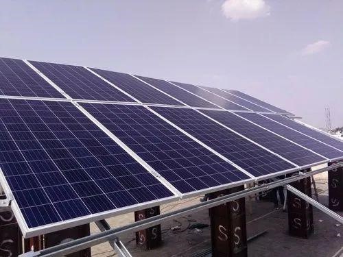
Large modules with 72 or 144 cells (typically 2.2m x 1.1m) are standard for large flat-roof commercial buildings and ground power stations, capable of reducing hardware costs for brackets and clamps by about 15% to 20%.
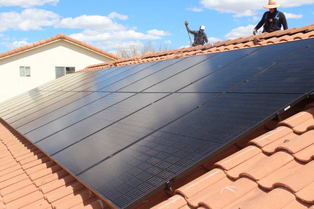
In contrast, small modules with 60 or 120 cells (height approx. 1.75 m) dominate residential installations, where shorter bodies can flexibly avoid chimneys, skylights, and ridge vents.
RVs and boats typically use only 100W to 200W dedicated boards, which mostly match 12V cell banks in voltage and are strictly limited to less than 1 meter in width to fit roof racks.
Complex Residential Roofs
Filling Like a Puzzle
The common Hip Roof in American suburbs consists of four triangles or trapezoids, and the installable area of the roof is narrow at the top and wide at the bottom.
· Geometric Fill Rate: Large modules are usually over 2.2 meters long and about 1.13 meters wide, with an area of about 2.5 square meters. Small modules are usually around 1.75 meters long and 1.04 meters wide, with an area of about 1.8 square meters. On a trapezoidal roof surface with a bottom width of 5 meters and a top width of 1 meter, if large modules are used, often only one row (2 panels) can be barely placed at the bottom, and the large triangular area remaining at the top cannot be utilized because the width is less than 2.2 meters.
· Layout Flexibility: Using shorter small modules, designers can adopt a "pyramid" layout: 3 panels at the bottom, 2 in the middle, and 1 at the top. This layout method can increase roof utilization from about 50% for large boards to over 75%. For residential roofs where every inch of space is expensive, the total system capacity can be increased by 1 kW to 2 kW.
Avoiding Roof Obstacles
Residential roofs are not only irregular in shape but also full of functional obstacles. Plumbing Vents, Attic Fans, Skylights, and Chimneys are the four major "roadblocks" for PV layout.
· Safety Clearance: The International Building Code (IBC) usually requires a clearance of at least 50 mm to 100 mm between modules and obstacles for drainage and snow sliding.
· Avoidance Advantage: Assume there is a 3-inch diameter vent pipe in the center of the roof. If a large module is used, this pipe may directly "cut off" the position where a large board could have been placed, causing the entire 2.5 square meter area to be forcedly abandoned. Small modules, due to their small single area, can be flexibly installed to the left or right of the vent pipe, or staggered up and down. In actual cases, facing a roof scattered with more than 3 vent pipes, using small modules can usually install 4 to 6 more panels than large modules.
Fire Pathway Reservation
In the United States and many developed countries, fire codes (such as NFPA 1 series) have hard regulations on the installation location of PV systems.
· Roof Ridge Setbacks: Codes usually require a width of 3 feet (about 91 cm) to be reserved on both sides of the ridge as a walking and demolition passage for firefighters during a fire.
· Physical Game: The slope length (Rafter Length) of ordinary American residential roofs from eaves to ridge is often between 12 feet and 16 feet.
o Deducting the 3-foot fire lane at the top and the 1-foot drainage reservation at the bottom, the available length may only remain 8 feet to 10 feet (about 2.4m to 3m).
o Awkwardness of Large Boards: After a 2.2-meter-long large board is installed vertically, the remaining space is insufficient to install another row, so only one row can be installed.
o Breakthrough of Small Boards: If a 1.7-meter-long small board is used, although only one row can be installed vertically, because it is shorter, at certain specific angles or using landscape installation, combined with precise rail layout, it is possible to squeeze out two rows in the same space (for example, using shorter 1.65-meter old specification boards or compact boards), or at least allow the installation position to be lower, avoiding the area with the highest wind speed at the ridge.
Load Bearing and Wind Pressure
Many houses built before the 1980s use 2x4 lumber for roof rafters instead of modern standard 2x6 lumber, and the spacing is also wider (24 inches center-to-center).
· Dispersed Point Load: Large modules weigh close to 30 kg to 35 kg per piece, and due to the large span, usually only four clamps are needed for fixing. Small modules are about 20 kg per piece. Although the total weight may be similar, due to the larger number of modules, the number of fixing hooks is also greater, which can distribute the weight more evenly across the entire roof structure, reducing the risk of fracture of a single rafter.
· Wind Resistance: Large modules have a large wind-receiving area, like huge sails. In hurricane-prone areas (such as Florida), large modules have extremely high requirements for the Uplift Resistance of the bracket system, often requiring extended bolts to be driven deep into the rafters. Small modules have a small single wind-receiving area. At the same wind speed, the tearing force on the bracket and roof structure is much smaller, usually meeting engineering certification requirements with standard 2.5-inch lag screws.
Construction and Safety
For steep roofs with a slope exceeding 30 degrees (7/12 Pitch), installation difficulty rises exponentially.
· Single Person Operation Limit: On steep slopes, installers usually need to hold a safety rope or ladder with one hand and only use the other hand and body to assist in carrying modules. Controlling a large board 2.2 meters long and weighing 30 kg in windy conditions is extremely dangerous and can easily lead to personnel falling or modules bumping and damaging roof tiles.
· Efficiency Reversal: Although theoretically installing large boards can reduce the number of wiring connections, on steep roofs, the time for two workers to cooperate to install one large board is often longer than for them to install two small boards separately. Because small boards (about 18-20 kg) can be easily clamped under the arm or carried on the back by one worker to climb the ladder, movement and positioning on the roof are also more agile.
Voltage Matching Details
Complex roofs often result in PV arrays being divided into multiple small "Sub-arrays", each orientation potentially having only 2 to 4 modules.
· Startup Voltage Threshold: Most String Inverters require at least 100V to 150V DC voltage to start working.
o Large Board Problem: If a small west-facing roof can only fit 2 large modules (each with Voc about 50V, operating voltage about 40V), the total voltage after series connection is only 80V, which cannot start the inverter, causing the power generation potential of this roof to be completely wasted.
o Small Board Solution: The same area may fit 3 to 4 small modules (each with operating voltage about 35V), and the series voltage can reach over 140V, enough to maintain inverter operation.
· Microinverter Advantage: Although Microinverters solve the voltage problem, large high-power modules (550W+) often exceed the continuous input current limit of mainstream microinverters (such as Enphase IQ8 series), leading to severe "Clipping". The power of small modules (350W-400W) matches the rated power of microinverters better, achieving a better system output ratio.
Commercial Ground Power Stations
Saving Bracket Consumables
Since brackets are usually designed by "piece" rather than by "watt", the larger the module, the less steel and aluminum allocated to each watt.
· Reducing Fixing Points: Suppose we want to build a 1MW (megawatt) ground power station.
o Small Scheme: Using 370W small boards, about 2703 panels are needed. If each panel needs 4 clamps, a total of about 10812 clamps and bolt assemblies are needed.
o Large Scheme: Using 550W large boards, only 1818 panels are needed. The number of clamps drops to 7272.
o Gap: Simply changing the module size directly reduces the procurement and installation work of more than 3,500 metal connectors.
· Piles and Beams: In ground mounts, pile driving is one of the most expensive processes. Large modules usually adopt vertical double-row (2-Portrait) or horizontal multi-row installation. Since the span of a single module is larger, under the same array length, large modules allow the spacing between piles to be slightly widened, or reduce the total number of rows of piles when covering the same area.
Construction Speed Competition
In commercial projects, Labor Rate is usually calculated by the hour, and installation speed directly determines profit margins.
· Action Repetition Rate: The installer's action flow is fixed: lift the board, position, snap in clamps, tighten bolts, plug in connectors. Completing this set of actions takes almost the same time whether for a 370W small board or a 550W large board.
· Efficiency Data:
o Installing 2,700 small boards requires repeating the above actions 2700 times.
o Installing 1800 large boards only requires repeating 1800 times.
o Although large boards are heavier (about 30-35 kg), modern commercial construction is usually equipped with mechanical assistance (such as vacuum cup lifters) or two-person assembly line operations. The result is that installing a 1MW power station of the same capacity, using large boards can save about 30% to 40% of module installation man-hours.
High Voltage System Matching
Commercial and utility-scale power stations currently generally adopt 1500V DC systems to reduce line losses and equipment costs.
Large modules are optimized for 1500V systems by design.
· String Length: The voltage parameters of large modules usually allow more or more reasonable numbers to be connected in series in a single string, making the string voltage close to the 1500V upper limit.
· Reduced Combiner Boxes:
o Since large modules have higher power per string, for the same 1MW capacity, the total number of strings required is fewer.
o The total length of DC Homerun Cables to be laid is significantly reduced, and the demand for input ports of Combiner Boxes or string inverters is also reduced accordingly.
o Reduced Failure Points: A common failure point in PV systems is the burning of MC4 connectors. Using large boards reduces the number of connectors by about 30%, statistically directly reducing the fire risk and poor contact failure rate over the full life cycle.
Tracking Bracket Compatibility
Modern large-scale ground power stations are increasingly using Single-Axis Trackers, allowing modules to turn with the sun like sunflowers, which can increase power generation by 15% to 25%.
· Rigidity Requirements: Tracking brackets generate torque when rotating and are prone to resonance (Galloping) on windy days. Large modules usually adopt thickened frames (35mm or 40mm) or Double Glass structures, which are more rigid and can serve as part of the structure to enhance the stability of the tracking system.
· Bifacial Power Generation: Many commercial-grade large modules are Bifacial, and the back can use ground reflected light to generate electricity. Since large-sized modules are sparsely arranged, the proportion of bracket shading on the back is relatively small, allowing for more effective use of bifacial gain.
RV & Marine Systems
Voltage Matching for 12V Cell Systems
The basic power architecture of RVs and boats is mostly built on 12V DC systems.
The output voltage of the solar panel must match the charging voltage window of the cell bank, which directly determines the selection cost of the charge controller.
· Native Compatibility of Small Boards: Standard 100W or 160W small monocrystalline panels usually have an Open Circuit Voltage (Voc) designed between 21V and 23V, and a Maximum Power Voltage (Vmp) of about 18V.
· Forced Conversion of Large Boards: Residential 350W or 400W large boards are usually composed of 72 or 144 half-cut cells in series, with Voc often as high as 40V or even 50V. If directly connected to a 12V cell, a PWM controller will simply pull the voltage down to the cell voltage, causing over 60% of the power to be wasted.
Dodging Roof Obstacles
Air conditioner outdoor units, satellite antennas, bathroom exhaust fans, and even kayak racks occupy precious space.
· Fragmented Layout: Taking a typical Mercedes Sprinter (Class B RV) as an example, the roof width is only about 1.7 meters, and the center is usually occupied by a roof-mounted air conditioner.
o Large Board Dilemma: A large module 2 meters long and 1 meter wide simply cannot fit into the long narrow space next to the air conditioner.
o Small Board Strategy: Since small boards come in various sizes (e.g., 100W boards are usually 1m x 0.5m, or even strip-shaped 50W boards), installers can play "Tetris", using the narrow corridors on both sides of the air conditioner, or placing them horizontally before and after the exhaust fan.
· Curvature Adaptation: Many Airstream RVs or sailboat decks have obvious curvature. Large glass-encapsulated modules are rigid and cannot bend. In the small module market, there are abundant Semi-flexible or CIGS thin-film products to choose from. These panels are usually limited to under 100W and can fit the streamlined curved surfaces of hatches or roofs, fixed directly with strong adhesive without drilling holes for screws, ensuring the sealing of the vehicle body.
Shadow Shading and Parallel Advantage
Campsites are usually located in woods, and when docked at a marina, you may be shaded by tall yachts next door.
· Resilience of Parallel Circuits: In mobile systems, All-Parallel wiring is universally adopted.
o Scenario Simulation: Assume there are four small 100W boards connected in parallel on the roof. When the car is parked in the shadow of a utility pole, one of the boards is shaded. Since they are in parallel, the other three boards are completely unaffected, and the system can still output 300W power.
o Risk of Series Connection: If a 400W large board (internal cells are mainly in series structure) is used, or two large boards are connected in series to reduce wire gauge, once leaves block a small area, the current of the entire string will be limited to the level of the shaded cell, causing the output power to instantly drop to near zero.
Aerodynamic Wind Resistance and Mechanical Strength
When an RV speeds on the highway at 110 km/h (about 70 mph), the solar panels on the roof withstand huge wind pressure and turbulence.
· Sail Effect: Large modules have a large area. If brackets (such as Z-brackets) are installed to raise the board body for heat dissipation, high-speed airflow will form a high-pressure zone under the board, generating huge Uplift Force.
· Vibration Hazard: Continuous vibration and bumps during vehicle driving will be transmitted to the modules. Large modules have a large span (over 2 meters) and lack support in the middle. Long-term vibration easily leads to Micro-cracks invisible to the naked eye in the glass, which in turn leads to hot spot effects.
· Marine Specificity: On sailboats or yachts, equipment must withstand high salt spray corrosion. Common cheap large commercial modules on the market may have an anodized layer thickness of only 10-15 microns on their aluminum alloy frames, and the junction box protection level may only be IP65.