Why Choose Portable Solar Modules | Foldable & Lightweight, Durability, Noise
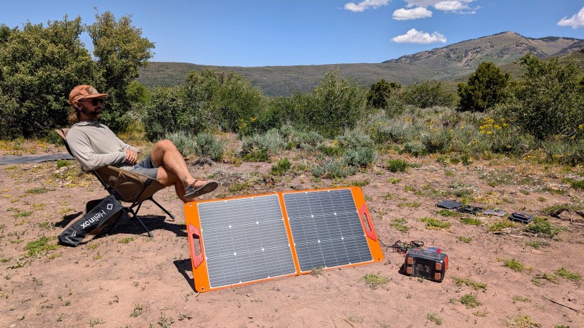
The portable module weighs only 4 kg after folding, uses ETFE encapsulation to achieve IP67 waterproofing, and achieves 0-noise power supply compared to 60-decibel fuel engines;
Simply unfold the stand, connect the power, and it is plug-and-play, making it suitable for quiet outdoor camping.
Foldable & Lightweight
Portable modules utilize ETFE or PET polymer films to replace traditional 3.2mm tempered glass, controlling the weight of a 200-watt module between 6 to 8 kilograms, which is more than 60% lighter than rigid photovoltaic panels of the same specifications.
Through a four-fold or two-fold structural design, the original 1.5 square meter light-receiving surface is reduced to just 60x55 centimeters after storage, with a thickness of approximately 40 mm.
This design, combined with an integrated TPE rubber handle, allows users to complete the entire process from taking it out of the vehicle to unfolding it for use within 30 seconds.
Weight Reduction via Polymer Materials
Ditching Glass and Aluminum Frames
A standard 100-watt rigid panel usually weighs around eight kilograms.
About 70% of this weight comes from the 3.2mm thick low-iron tempered glass, and another 20% comes from the anodized aluminum alloy frame used to fix the glass and backsheet.
Although the density of glass is about 2.5 g/cm³, and the density of polymers (such as ETFE or PET) is typically between 1.3 to 1.7 g/cm³, the real difference lies in thickness.
· Thickness Comparison: Rigid glass thickness is fixed at 3.2mm or even 4mm, while the thickness of the polymer encapsulation layer is usually only 0.025mm to 0.5mm.
· Structural Change: After removing the aluminum frame, the module no longer relies on metal edges for rigidity but relies on the composite lamination strength of internal materials.
Under equivalent power, the weight of the bare board after removing the glass and frame is usually only 15% to 20% of traditional modules.
Even counting the nylon fabric shell and stand added for portability, the weight of the final product is only 40% to 50% of a rigid board.
Surface Switched to ETFE Film
In the current portable solar market, ETFE (Ethylene Tetrafluoroethylene) has gradually replaced early PET (Polyethylene Terephthalate) materials, becoming the preferred surface for high-end lightweight modules.
ETFE is not just light; it offers extremely high data performance in physical properties:
1. Transmittance: The light transmittance of ETFE film is as high as 95%, which is slightly higher than the 91%-93% of ordinary tempered glass.
2. Weather Resistance: This fluoropolymer has extremely strong chemical stability. It can withstand temperature fluctuations from -65°C to +150°C without becoming brittle or softening. In contrast, cheap PET materials usually yellow and crack within 18 to 24 months under long-term UV irradiation, leading to a decrease in transmittance.
3. Self-Cleaning Ability: ETFE has a non-stick surface (similar to non-stick pan coatings) with a very low coefficient of friction. Dust and dirt find it hard to adhere, and rain washing can carry away surface obstructions, reducing the frequency of manual maintenance.
Manufacturers usually also apply textured treatment (commonly called honeycomb or diamond texture) to the ETFE surface.
This microscopic structure not only increases the surface's diffuse reflection capability, allowing the module to capture more photons under low-angle sunlight in the early morning and evening, but also further reduces energy loss caused by surface reflection.
Backsheet Weight Reduction
Rigid boards use TPT composite backsheets plus aluminum frames, while foldable boards usually use FR4 fiberglass boards or TPE composite materials as backsheets.
· FR4 Material: This is a fiberglass-reinforced epoxy resin commonly used as a substrate for circuit boards. It has extremely high mechanical strength, preventing solar cells from breaking due to excessive bending without adding too much weight.
· Heat Resistance: Although the heat dissipation performance of this composite backsheet is not as good as glass, combined with the thin encapsulation layer, the heat accumulation effect does not increase significantly. Under Standard Test Conditions (STC), its operating temperature coefficient performance is stable.
The introduction of fiberglass backsheets gives the entire module certain semi-flexible characteristics.
It allows the module to deform within a certain range (usually a bending arc within 30 degrees) to adapt to uneven ground or car roofs, without causing micro-cracks in the cell due to lack of support like pure flexible boards.
Thinner Cells, Higher Efficiency
High-end portable modules often select IBC (Interdigitated Back Contact) cells or shingled technology cells.
Feature | Conventional Al-BSF Cell | IBC / High-Efficiency Monocrystalline Cell |
Conversion Efficiency | 18% - 20% | 22% - 24% |
Front Grid Lines | Has silver metal grid lines | No obstruction, all-black appearance |
Mechanical Strength | Fragile, needs glass protection | Copper backing reinforcement, bend-resistant |
Taking SunPower's Maxeon cell as an example, it uses a solid copper base as the foundation of the cell.
This design not only has good conductivity, but more importantly, copper has ductility.
When the module bends slightly or is impacted, the copper base can keep the circuit connection intact, preventing micro-cracks from expanding and causing power attenuation.
Since the conversion efficiency reaches 23% or even higher, to generate the same 200 watts of power, the required cell area is smaller.
The reduction in area directly translates to a reduction in material usage, thereby further reducing the overall weight.
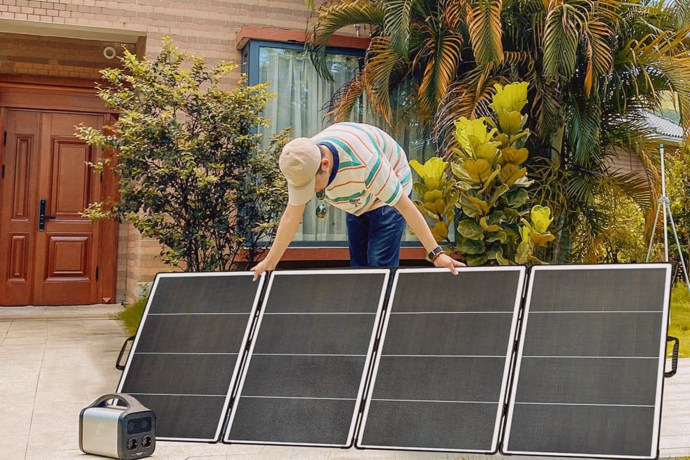
Folding Space Management
Packing a Power Station Like Origami
A standard 200-watt monocrystalline silicon photovoltaic module requires a physical light-receiving area of at least about one square meter.
If it is a traditional rigid board, you must carry a huge rectangular object about 1.5 meters long and 0.7 meters wide.
This is a huge space occupier for car trunks, small SUVs, or even apartment storage rooms.
Engineers cut a whole large cell panel into four independent series parts and combine them through flexible connections.
· Size Compression Ratio: Taking a mainstream 200-watt folding bag on the market as an example, its unfolded size is usually about 230cm x 55cm. But after four-folding, the storage size instantly becomes 60cm x 55cm.
· Thickness Stacking: Although the single-layer thickness is extremely thin, the total thickness after folding (including the outer protective fabric) is usually controlled between 40mm to 60mm.
Fabric Hinges and Millimeter-Level Gaps
Rigid metal hinges are too heavy and prone to rust, so portable modules universally adopt high-strength industrial fabrics as connection layers.
To ensure that the two panels can be completely flush after folding without squeezing the junction box or cables in the middle, engineers reserve a precise gap between the cell panels.
1. Gap Width: Usually 20mm to 30mm. This width is calculated to ensure the continuity of the cell panels when unfolded, while ensuring enough margin to accommodate the thickness of the panels themselves when folded.
2. Stress Release: This soft connection eliminates the mechanical stress brought by rigid folding. Internal wires (busbars) usually take an "S" shape or are wrapped in thickened fabric channels to withstand thousands of opening and closing operations without metal fatigue fracture.
3. Fabric Selection: The outer wrapping is usually selected from 500D to 1000D Oxford cloth or Cordura fabric.
Magnetic Closure and Integrated Handle
Early folding boards usually used Velcro or plastic buckles to fix the folded state. However, Velcro easily attracts dry grass and dust, and plastic buckles easily become brittle and break at low temperatures. Modern high-end modules tend to use embedded magnetic designs.
· Invisible Magnets: Manufacturers will bury Neodymium magnets inside the handle or under the fabric layer at the panel edge. When the user closes the board, the top and bottom ends will automatically snap together and align. This suction force is usually set between 1.5 kg to 3 kg, ensuring it won't automatically fall apart when carried, while allowing the user to easily pull it open with one hand.
· Integrated Handle: The handle is no longer an extra accessory but is directly molded in TPE (Thermoplastic Elastomer) material, integrated with the junction box shell at the top.
No More Cable Tangling
A standard set of modules is usually equipped with a 3-meter long connection cable.
If stuffed randomly into a bag, it often comes out like a tangled mess. Portable modules solve this problem through an integrated storage pouch.
This storage pouch is usually located on the back of the outermost layer of the folding bag, using breathable mesh or a waterproof zipper structure:
· Fixed Position: The Junction Box is usually fixed directly inside the storage pouch. After the cable leads out from the junction box, it is coiled directly in the pouch.
· Scratch Protection: The lining of the storage pouch is usually soft material. This is not just for holding wires, but to prevent hard MC4 terminals or Anderson connectors from squeezing or scratching the backsheet of the solar panel during folding and transport.
· Accessory Space: The space margin of this bag is usually sufficient to accommodate user-purchased adapters, parallel cables, or even small MPPT controllers, realizing a "grab bag and go" storage logic.
Stand Angle Adjustment
Chasing the Sun Generates 30% More Power
The working principle of solar panels determines that photoelectric conversion efficiency is highest when sunlight enters the cell surface vertically (i.e., the incident angle is 90 degrees).
For rigid boards fixed to the roof of an RV, they can only lie flat to receive light most of the time.
In the morning, evening, and winter when the solar altitude angle is low, power generation efficiency is greatly discounted.
The adjustable Kickstands behind portable modules solve this physical limitation. By adjusting the stand, users can keep the panel always facing the sun.
· Efficiency Improvement Data: In mid-latitude regions of the Northern Hemisphere (such as around 40 degrees north latitude), adjusting the solar panel to an appropriate tilt angle compared to horizontal placement can usually increase the total daily power generation by 25% to 30%.
· Peak Maintenance Time: Fixed boards may only reach peak power between 11 am and 1 pm. Portable boards with stands, through manual turning and angle fine-tuning every few hours, can extend the high-output period of peak power to 9 am to 3 pm.
A Few Straps Handle the Support Structure
Manufacturers typically use elastic nylon straps combined with hard plastic boards to implement support.
1. Structural Composition: In the stored state, the stand adheres closely to the backsheet via Velcro, adding almost no thickness. When in use, the user pulls it open, and the bottom is connected to the bottom of the panel by a limiting strap, forming a stable triangular structure.
2. Angle Control: This limiting strap is often designed with multiple adjustment holes or stepless adjustment buckles. Users can freely adjust the tilt angle of the panel between 30 degrees and 60 degrees by changing the effective length of the strap.
3. Wind Resistance: Although the structure seems simple, the triangle is the most stable geometric shape. Well-designed fabric stands can usually withstand a breeze of Force 3 to 4 without tipping over.
Different Seasons Require Different Angles
In summer, the direct point of the sun moves north, and the sun is very high at noon;
In winter, the sun's position is southerly, and the light is severely tilted.
The stand adjustment function of portable modules allows users to adapt to this seasonal change, which is difficult for fixed roof boards to achieve.
· Summer Setting: When camping in summer, the sun is close to overhead. At this time, the strap behind the stand should be shortened to make the angle between the panel and the ground smaller (about 20 degrees to 30 degrees) to receive high-angle sunlight.
· Winter Setting: Winter is a difficult time for off-grid power, with short sunshine hours and weak intensity. At this time, it is necessary to loosen the strap and stand the panel up to a larger angle (about 45 degrees to 60 degrees) to capture low-angle oblique light as vertically as possible.
Data shows that in December, the actual daily power generation of a properly adjusted 100-watt portable board is often higher than that of a 200-watt fixed board laid flat on the roof.
Actual Yield Comparison: Refusing to Lay Flat
To intuitively show the benefits of stand angle adjustment, we can look at a set of measured data simulations on a sunny autumn equinox day (moderate sunshine conditions).
Assuming the location is at 45 degrees north latitude, using the same model 100-watt ETFE portable module.
Time Point | Flat on Ground (0 degree angle) | Using Stand (45 degree angle) | Power Difference |
09:00 AM | 35 Watts | 68 Watts | + 94% |
12:00 PM | 72 Watts | 94 Watts | + 30% |
15:00 PM | 38 Watts | 70 Watts | + 84% |
17:00 PM | 10 Watts | 35 Watts | + 250% |
Data Interpretation:
1. Huge Morning/Evening Difference: At 9 am and 3 pm, the sun slants severely. Flat boards lose energy due to a large amount of light reflection, while boards supported by stands can still maintain a high conversion rate.
2. Improvement even at Noon: Even at noon, due to latitude reasons, sunlight does not shoot absolutely vertically to the ground. The 45-degree stand correction still brought a power increase of about 22 watts.
3. All-Day Accumulation: This difference translates into a huge power gap at the end of the day. Using a stand may obtain 600 watt-hours of total electricity, while laying flat may only obtain 380 watt-hours.
Durability
Compared to old-style PET materials, their light transmittance stabilizes at over 95%, and their aging resistance cycle is as long as 10 years.
Mainstream products meet IP67 or IP68 protection standards, capable of withstanding immersion in one meter of water for 30 minutes without damaging the circuitry.
Their multi-layer lamination structure abandons fragile glass, passes drop tests from 0.5 meters to 1.2 meters, and maintains over 80% of rated power output in environments with temperature differences from -20°C to 60°C.
ETFE Coating Lifespan
More Light Penetration
The optical performance of ETFE film is very close to optical glass, with full-spectrum light transmittance typically stabilizing at 95% to 97%.
In contrast, the transmittance of ordinary PET material is typically between 85% to 90%.
This 5% to 7% difference is particularly noticeable when light is weak in the morning and evening (low irradiance).
The refractive index of ETFE is about 1.40. This value is very close to air, so reflection loss is minimized when light enters the protective layer from the air.
Once yellowed, transmittance will drop further to below 70%.
However, ETFE is almost completely transparent to UV rays; it allows UV rays to penetrate and be utilized by the cells below or absorbed by the backsheet, without aging itself due to UV irradiation.
Hard-to-Break Molecular Structure
In its molecular chain, the bond energy of the carbon-fluorine bond (C-F) is as high as 485 kJ/mol. This is one of the strongest chemical bonds known in organic chemistry.
The energy levels of UV radiation in nature, chemical substances in acid rain, or corrosive modules in bird droppings are usually insufficient to break this high-strength carbon-fluorine bond.
This allows ETFE to maintain its mechanical strength at over 80% of its initial value even after 10 to 20 years of outdoor exposure.
In contrast, the tensile strength of PET or other low-cost polymers typically drops by 50% after 24 months of outdoor exposure, and micro-cracks visible to the naked eye begin to appear on the surface.
No Deformation Even Under High Heat
The surface temperature of dark solar panels under direct outdoor sunlight is extremely high, typically reaching 65°C to 75°C at noon in summer.
The melting point of ETFE is about 260°C to 270°C, and the upper limit for long-term continuous use temperature can reach 150°C.
In any extreme natural high-temperature environment on Earth, it will not soften, creep, or physically deform.
Ordinary thermoplastics begin to soften at around 80°C, causing delamination between the protective layer and the EVA (Ethylene Vinyl Acetate) adhesive film below.
Once delaminated, air enters the gap, not only blocking light but also producing condensation due to temperature differences, causing short circuits.
ETFE's good thermal stability ensures the integrity of the encapsulation structure.
Its linear coefficient of thermal expansion is about 9.0 × 10⁻⁵ /K, which matches well with the expansion rate of the cells, reducing internal stress caused by thermal expansion and contraction.
Surface Texture Grabs Light
The surface of many high-end ETFE modules is not completely smooth but presents an uneven honeycomb or dot matrix texture.
Surface Morphology | Working Principle | Actual Benefit |
Honeycomb Convex/Concave Surface | Increases effective surface area, produces diffuse reflection and refraction. | When sunlight hits at a low angle (such as sunrise and sunset), the texture can "refract" light into the cells instead of reflecting it directly back into the atmosphere. |
Flat Smooth Layer | Only effective for receiving vertically incident light; oblique light tends to cause specular reflection. | Prone to causing glare, and the light capture rate is lower during non-noon periods. |
This texture treatment makes the power generation of ETFE modules 3% to 5% higher than smooth surface modules of the same power in the morning and evening.
At the same time, the concave-convex surface increases the contact area with the EVA film, resulting in higher peel strength after lamination and greater resistance to tearing.
Dust and Rain Can't Stick
ETFE has extremely low surface energy, about 23-25 mN/m.
This characteristic is similar to non-stick pan coatings (PTFE), giving it strong hydrophobicity and oleophobicity. Water droplets cannot spread on the ETFE surface, and the contact angle is usually greater than 90 degrees.
1. Self-Cleaning Effect: When rainwater falls on the surface, it forms round water beads and rolls off under gravity. During the rolling process, the water beads take away surface dust and dirt.
2. Maintenance Cost: Users do not need to use detergents for scrubbing frequently. In contrast, after PET surfaces age, they become rough and sticky, easily adsorbing dust to form a "mud shell" that is difficult to clean and blocks light.
Waterproof and Dustproof Rating
Dust Can't Get In At All
Portable solar panels are often placed directly on the ground, beaches, or rocks for use. IP6X is currently the highest dustproof standard.
When testing this standard, the laboratory establishes a negative pressure environment, with the pressure difference usually set at 20 millibars (mbar).
Testers suspend talcum powder (particle size screening standard is 50 microns to 75 microns between each wire) in the test chamber at a density of 2 kg per cubic meter.
After eight hours of continuous pumping tests, the device casing is opened. It only passes if there is no dust deposition visible to the naked eye inside.
Box Filled with Potting Compound
The Junction Box is that small black square box on the back of the solar panel, hiding bypass diodes and cable connection points. It is the defensive focus of the entire system.
To achieve IP67 or higher levels, the interior of modern high-quality module junction boxes leaves no air but adopts a Potting Process.
· Filling Material: Typically uses thermally conductive silicone or epoxy resin.
· Physical Isolation: The colloid completely wraps the diodes and metal soldering points. Even if the shell breaks, water molecules cannot contact the live parts.
· Heat Dissipation Function: Potting compound is not only waterproof but can also conduct the heat generated when the diode works (usually 60°C to 85°C) to the outside, preventing overheating from melting the sealing ring.
And fully potted junction boxes, even if completely submerged in one meter deep water for 30 minutes, maintain an internal insulation resistance of over 400 Megohms (MΩ).
Interfaces Must Not Let Water In
Many users focus on whether the board is waterproof but overlook the connection cables. The waterproof performance of MC4 or Anderson interfaces also needs to reach IP67.
Standard waterproof MC4 connectors contain an O-ring seal made of silicone or fluororubber (Viton).
Module Part | Waterproof Mechanism | Key Parameter | Consequences of Failure |
Plug Front End | O-ring Seal | Hardness Shore A 60-70 | Moisture entry causes arc oxidation |
Cable Tail | Nut Fastening | Torque 2.5 - 3.0 N·m | Rainwater flows along the cable into the interior |
If the connector is not plugged in tightly, or the sealing ring is missing, the contact resistance at the interface will skyrocket from the normal 0.3 milliohms.
After water enters, an electrolytic reaction occurs, corroding the tin-plated copper pins, causing resistance to increase further.
When high current passes through, high temperatures are generated, potentially melting the plastic shell.
Seaside Salt Spray Corrosion Resistance
The air at the seaside is full of salt spray (sodium chloride particles), the corrosiveness of which is several times that of ordinary rainwater.
High durability modules need to pass the IEC 61701 Salt Mist Corrosion Test (Level 6 is the highest standard). The test process is extremely rigorous:
1. Spraying: Spray using a 5% concentration sodium chloride solution.
2. Heat and Humidity: Let stand in an environment of 40°C high temperature and 93% humidity.
3. Cycle: The above process is repeated for eight weeks (1,344 hours).
The metal frame (if any), grounding holes, and laminated edge sealant of modules that pass this test will not peel or rust due to salt erosion.
For portable panels used in seaside camping or on yachts, it is essential to check whether the product manual mentions Salt Mist Corrosion certification.
Glass-Free Pressure Resistant Layer
Hail Bounces Off
In the standard IEC 61,215 hail impact test, testers use ice balls with a diameter of 25 mm to impact 11 specific stress points on the module surface at a speed of 23 m/s (about 82.8 km/h).
For tempered glass, if the impact force exceeds the critical value, the glass will shatter due to stress.
However, for glass-free ETFE laminates, the material has excellent toughness.
When high-speed hail hits, the surface layer instantly dents downwards, absorbing kinetic energy, and then rebounds quickly like a trampoline to restore its original state.
This characteristic of "conquering rigidity with softness" allows high-quality portable modules to withstand impacts with kinetic energy up to 1.2 Joules without damage.
In actual outdoor scenarios, even if a metal flashlight or camping hammer weighing 500 grams is accidentally dropped, as long as the height does not exceed 1 meter, the module surface will usually only leave tiny traces, rather than shattering like glass.
Bending Thirty Degrees No Problem
Monocrystalline silicon wafers themselves are very brittle, with a thickness of only 160 microns to 180 microns, and will break if bent slightly.
The glass-free pressure-resistant layer endows the module with certain flexibility through a special encapsulation process.
This structure allows the module to undergo arc bending of 30 degrees to 45 degrees. The principle lies in:
1. Neutral Layer Design: By adjusting the thickness ratio of the upper and lower encapsulation materials (EVA and backsheet), the fragile solar cells are placed in the "neutral layer" position of bending stress.
2. Bending Radius: The minimum bending radius of high-quality modules can usually reach 150 mm or even smaller.
Backsheet Uses Fiberglass
To compensate for the lack of rigidity after removing glass, high-end portable modules add fiberglass to the backsheet material or use FR4 epoxy resin boards as a support layer.
The tensile strength of this composite backsheet is usually over 100 MPa, which is 2 times that of ordinary PET plastic backsheets.
· Anti-Puncture: In the wild, the ground is often covered with sharp stones or branches. The thickness of the reinforced backsheet is usually between 1.5mm to 2mm, which can effectively prevent sharp objects from piercing the module from the back and damaging the internal cells.
· Heat Dissipation: Although the thermal conductivity of composite materials is not as good as glass, modern processes increase thermal conductivity to about 0.3 W/(m·K) by adding thermally conductive fillers, which is sufficient to cope with the heat generated when the cell is working, preventing local temperatures from exceeding 85°C.
Unbroken by Road Bumps
This vibration frequency is usually between 10 Hz to 500 Hz.
Rigid glass modules, due to their large mass (usually over 20 kg), generate huge inertial forces during bumps, easily causing loose fixing brackets or stress cracks in the glass.
Glass-free modules are light in weight (usually 4 kg to 7 kg), have small inertia, and the EVA (Ethylene Vinyl Acetate) film in the laminated material has damping characteristics similar to rubber.
After curing, the cross-linking degree of the EVA film reaches over 85%. It acts like a soft cushion wrapping the solar cells, effectively absorbing and dissipating vibration energy.
Under the SAE J1455 vehicle vibration test standard, after 100,000 random vibration cycles, the connection reliability of the internal circuit of the glass-free module remains intact, without fatigue fracture of the soldering ribbons.
Noise
Portable solar modules use the photovoltaic effect to convert light energy into electrical energy.
The entire process involves no mechanical movement or fuel combustion, so the operating noise is strictly maintained at 0 dB (decibels).
In contrast, even modern inverter fuel generators labeled "silent" usually have noise values between 50 dB and 65 dB at a distance of 7 meters, equivalent to a running dishwasher or street background sound.
Operating Principle Differences
Electron Movement Has No Sound
Inside a monocrystalline silicon cell is the transition of microscopic particles, not the collision of macroscopic objects.
When photons in sunlight hit the P-N junction on the surface of the silicon wafer, the energy of the photons is absorbed by the semiconductor material, exciting electrons to break away from the nucleus and become free electrons.
These electrons move directionally under the action of the built-in electric field, forming a current.
Whether the output power of the solar panel is 100 watts or 400 watts, the sound wave energy produced at the physical level is zero.
Even under full load, high-quality bypass diodes dissipate the power generated by shadow occlusion in the form of heat, with absolutely no acoustic output.
The Explosion Sound of Internal Combustion Engines
Taking a common four-stroke gasoline generator as an example, the sources of noise generated by its internal mechanical operation are very complex and difficult to completely eliminate through simple physical isolation:
1. Intake Stroke: The vacuum created by the downward movement of the piston sucks air and fuel into the cylinder. The high-speed airflow through the intake valve produces a high-frequency "hissing" aerodynamic noise.
2. Compression Stroke: The piston moves up to compress the mixed gas. The crankshaft and connecting rod bear huge mechanical pressure, and the fitting clearance between metal parts produces mechanical knocking sounds.
3. Power Stroke (Noise Peak): The spark plug ignites, the mixed gas explodes instantly, and the pressure in the cylinder rises sharply to dozens of atmospheres. This explosive energy release directly impacts the piston, producing a dull and penetrating low-frequency roar.
4. Exhaust Stroke: The burnt exhaust gas rushes out of the exhaust valve at extremely high speed and pressure. Although the muffler reduces exhaust speed through a labyrinth structure composed of porous pipes and partitions, it cannot completely eliminate the blasting sound produced by high-speed airflow jets.
Noise Source | Physical Mechanism | Frequency Characteristic | Penetration Ability |
Combustion Explosion | Rapid expansion of gas in cylinder | Low Frequency (50-200 Hz) | Extremely strong, can penetrate walls and car bodies |
Mechanical Friction | Movement of pistons, crankshafts, valves | Mid-High Frequency (500-2000 Hz) | Medium, decays fast with distance |
Exhaust Airflow | High-pressure gas impacting atmospheric environment | Broadband | Strong, travels far with wind direction |
Photovoltaic Effect | Electron energy level transition | No Sound Waves | Zero |
Resonance Caused by Vibration
When the engine is running at high speed, the entire machine vibrates because the reciprocating inertial force of the piston cannot be completely balanced.
Even if high-end models are equipped with rubber damping pads, this vibration will still be transmitted to the ground.
If the generator is placed on a wooden deck, RV rack, or hard ground, the ground will be driven like a speaker diaphragm, producing secondary noise.
This low-frequency humming usually occurs below 100 Hz. Although the human ear is not sensitive to this frequency band, the body can feel the pressure, and the attenuation rate of this low-frequency sound wave in open outdoor areas is extremely low, often still clearly audible 50 meters away.
Campground Noise Regulations
Must Stop at 10 PM
According to Title 36 CFR 2.12, the quiet hours are usually mandated from 10:00 PM to 6:00 AM the next day.
Within this time window, any motorized equipment generating noise exceeding 60 decibels (A-weighted) must be forcibly shut down.
If you rely on a fuel generator to charge RV batteries or run heaters, you must cut the power as soon as 10 PM arrives.
For users who need to use CPAP machines or keep car refrigerators running continuously at night, this constitutes a huge risk of power outage.
The solution of portable solar modules combined with energy storage power supplies is completely unaffected by this restriction.
Since the solar system is completely silent when discharging (powering devices), you can continue to use high-power appliances at 2 AM.
As long as there is electricity in the cell, the entire 24 hours constitute your "legal operation time".
Decibels Measured During the Day Too
Even during daytime hours when generator use is permitted (usually 8 AM to 8 PM), noise caps still exist.
The limit standard for audio equipment in most National Parks and State Parks is: Measured at a distance of 50 feet (about 15 meters) from the sound source, noise must not exceed 60 decibels.
A standard 2000-watt Honda or Yamaha inverter generator, in economy mode (low load), has a nominal noise level of about 52 to 59 decibels at 7 meters.
Once a microwave or air conditioner is connected causing the load to increase, the speed increases, and the noise will instantly soar to 65 decibels or even over 70 decibels.
At this time, if a Ranger passes by with a decibel meter, you face the risk of violation.
In contrast, whether a solar panel is in a 120-watt trickle charge state or a 400-watt full load input state, its sound pressure level always remains at the level of environmental background sound, completely exempt from any decibel test.
Only Two Hours for Power Generation
In some camping areas of Yellowstone or Glacier National Park, generator usage time is further compressed.
For example, some campgrounds stipulate that generators can only run within the following three short windows:
· Morning: 8:00 - 10:00
· Noon: 12:00 - 14:00
· Evening: 16:00 - 18:00
You only have six hours a day to replenish energy, and someone must stay at the campsite to operate the equipment switch.
As long as there is sunlight, the panel is working.
You can unfold the folding solar panel and connect it to the power source before leaving the campsite at 8 AM.
It will continuously and automatically collect energy during your 8-hour hike, requiring no manual intervention throughout the process, and is not restricted by time windows.
Regulation Item | Fuel Generator Restriction | Solar Module Restriction |
Quiet Hours | 22:00 - 06:00 Strictly Prohibited | No Restriction |
Daytime Noise Cap | Must not exceed 60 dB at 15 meters | Always lower than ambient background sound |
Operating Window | Some camps limited to 8-10 am / 4-6 pm | Works all times from sunrise to sunset |
Unattended | Prohibited (Need anti-theft and fire monitoring) | Allowed (Passive energy collection) |
Private Campsites Are Even Stricter
Besides public lands, private chain campsites like KOA (Kampgrounds of America) or Good Sam have a zero-tolerance attitude towards noise.
To ensure the experience of most customers, these campsites usually arrange RVs using generators in specific remote areas, or even completely prohibit the use of non-vehicle (portable) generators.
This is because low-frequency noise has strong penetration and psychological intrusiveness.
Even if the generator meets decibel standards, its continuous low-frequency vibration (drone sound) will make neighbors a few meters away feel annoyed.
In private campsites, complaints from neighbors usually lead directly to management intervention.