High-Efficiency Monocrystalline Solar Panels | Are They Right for Your
High-efficiency monocrystalline panels have conversion rates exceeding 22%, increasing capacity by 15% for the same area, making them suitable for users with limited roof space;
Although the initial cost is 10% higher, the 30-year linear degradation is less than 13%, resulting in higher returns over the full cycle.
Efficiency & Performance
Monocrystalline panels rely on high-purity silicon crystal structures to boost commercial mass-production photoelectric conversion efficiency to 20% to 24%, significantly outperforming the 15%-17% of polycrystalline products.
With a temperature coefficient as low as -0.34%/°C, they suffer less power loss under high summer temperatures.
In terms of durability, the first-year degradation of monocrystalline modules is typically below 2%, followed by a linear annual degradation of only 0.55%, ensuring that over 84.8% of the original power output is retained after 25 years.
Conversion Rate
Panel Conversion Principle
Under Standard Test Conditions (STC), each square meter receives 1000 watts (1,000 W/m²) of sunlight.
If a 1-square-meter panel can output 200 watts of electricity, its conversion rate is 20%.
The reason monocrystalline silicon can break the 20% threshold stems from its atomic arrangement structure.
Unlike the chaotic Grain Boundaries inside polycrystalline silicon, which act like roadblocks hindering electron flow, monocrystalline silicon consists of a single continuous lattice.
This structure reduces energy loss caused by electron recombination, drastically lowering traffic jams in electron flow.
P-type PERC Technology
PERC (Passivated Emitter and Rear Cell) technology adds a dielectric passivation layer to the back of the cell.
· Photon Capture: This structure can "reflect" photons that penetrated the cell but were not absorbed back into the cell, giving photons a second chance to generate current.
· Data Performance: The mass-production efficiency of P-type PERC monocrystalline panels typically stabilizes at 20.4% to 21.6%.
· Degradation Characteristics: Since P-type silicon wafers are doped with Boron, they react with oxygen when initially exposed to sunlight to produce Boron-Oxygen complexes, causing a Light Induced Degradation (LID) of 2% to 2.5% in the first year.
N-type TOPCon Technology
As P-type cells approach their theoretical efficiency limit (about 24.5%), N-type TOPCon is becoming the new mainstream.
· Doping Difference: N-type silicon wafers are doped with Phosphorus, which has a naturally higher tolerance for metal impurities and completely eliminates LID caused by Boron-Oxygen complexes.
· Efficiency Boost: By preparing an ultra-thin tunnel oxide layer on the back, carrier recombination is further reduced. Currently, mass-produced TOPCon panel efficiency has generally reached 22.0% to 23.2%.
· Bifaciality: For users installing on light-colored roofs or ground mounts, the bifaciality (rear-side power generation capability) of TOPCon can reach 80% - 85%, far higher than PERC's 70%.
Heterojunction & IBC
This is the high-end field pursuing ultimate performance, usually used in scenarios with extremely small roof areas or extremely high esthetic requirements.
· Heterojunction (HJT): Combines crystalline silicon and amorphous silicon thin-film technology. It deposits amorphous silicon layers on both sides of the monocrystalline silicon wafer to form excellent surface passivation. The mass-production efficiency of HJT panels is between 22.5% and 23.8%, and the manufacturing process has fewer steps than TOPCon, but equipment costs are higher.
· IBC (Interdigitated Back Contact): It moves both positive and negative electrodes to the back of the cell, leaving no metal grid lines on the front to block sunlight. The increase in light-receiving area directly pulls up efficiency, with commercial IBC panel efficiency reaching 23.0% to 24.2%.
Spatial Power Calculation
The real value of high conversion rates lies in "Power Density." For common 60-cell or 66-cell panels (size approx. 1.7m x 1.0m):
1. Polycrystalline (17%): Single panel power approx. 275W - 285W.
2. Monocrystalline PERC (21%): Single panel power approx. 350W - 370W.
3. Monocrystalline HJT/IBC (23%): Single panel power approx. 400W - 420W.
High Temperature Power Performance
Real Panel Temperature
In reality, the data mentioned is measured in a laboratory environment at 25°C. In the real world, dark solar panels absorb a significant amount of heat.
· Temperature Rise Magnitude: At noon in summer, if the ambient temperature is 30°C, the panel surface temperature will typically reach 60°C to 65°C. If it is an all-black module with a black backsheet, the temperature may even breach 70°C.
· Physical Phenomenon: As the silicon wafer temperature rises, the band gap within the semiconductor shrinks, causing the open-circuit voltage (Voc) to drop significantly. Although the short-circuit current (Isc) rises slightly, the overall product (Power) shows a downward trend.
Temperature Coefficient
The Pmax Temperature Coefficient is a metric measuring the panel's "heat resistance," with the unit %/°C.
It indicates the percentage of power drop for every degree the temperature rises above 25°C.
The closer the value is to 0, the better the performance.
The difference in coefficients between technology routes is significant:
1. Traditional Polycrystalline: Coefficient is about -0.40% to -0.43% /°C.
2. Standard Monocrystalline PERC: Coefficient optimized to -0.34% to -0.36% /°C.
3. N-type TOPCon: Coefficient further reduced to -0.30% to -0.32% /°C.
4. Heterojunction (HJT): Best performance, with coefficients as low as -0.24% to -0.26% /°C.
Actual Generation Loss
To quantify this difference, let's simulate a typical high-temperature summer scenario.
Set Conditions:
· Ambient Temperature: 35°C
· Panel Operating Temperature: 65°C (40°C higher than STC standard)
· Nominal Power: 400W Panel
Calculation Process & Results:
· Polycrystalline Panel (-0.41%):
Power Loss = 40°C (Temp Diff) x 0.41% = 16.4%
Actual Output = 400W x (1 - 16.4%) = 334.4W
· Monocrystalline PERC (-0.34%):
Power Loss = 40°C (Temp Diff) x 0.34% = 13.6%
Actual Output = 400W x (1 - 13.6%) = 345.6W
· Heterojunction HJT (-0.26%):
Power Loss = 40°C (Temp Diff) x 0.26% = 10.4%
Actual Output = 400W x (1 - 10.4%) = 358.4W
At the same time, simply due to the difference in temperature coefficients, the HJT monocrystalline panel outputs 24W more power than the polycrystalline panel.
In a system with 20 panels, this is equivalent to instantaneously having 480W more power, almost equal to installing an extra panel.
Long-term Degradation Rate
First Year Light Induced Degradation
For the current market mainstream P-type monocrystalline PERC panels, Boron is doped into the silicon wafers.
When Boron atoms meet trace Oxygen atoms in the silicon wafer under sunlight, they form "Boron-Oxygen complexes."
This microscopic defect captures electrons, causing the panel's power to permanently drop by 2% to 3% within the first few weeks of installation.
The 400W panel you bought might have a stable actual power of around 390W after the first month.
However, the new generation of N-type monocrystalline panels (like TOPCon or HJT) changes this rule.
Phosphorus atoms do not react with Oxygen in this way, so the first-year degradation of N-type panels is extremely low, usually controlled within 1%, and some products even claim "Zero LID."
Linear Annual Degradation Rate
At this stage, it's not just light at work; UV radiation, thermal cycling, and humidity all cause slow material aging.
We can compare the average annual degradation data of three technology routes:
· Traditional Polycrystalline Silicon: Due to many grain boundaries and impurity diffusion channels, the average annual degradation rate is usually around 0.7%.
· Standard Monocrystalline PERC: The current top-tier standard is 0.55%.
· N-type Monocrystalline / Double Glass Modules: High-end products have compressed this figure to 0.40%.
The Gap Behind the Numbers:
Although 0.55% and 0.40% seem to differ by only 0.15%, the gap becomes astonishing after 25 years of compound accumulation.
1. 0.7% Degradation Rate: Residual power in year 25 is about 80.0%.
2. 0.55% Degradation Rate: Residual power in year 25 is about 84.8%.
3. 0.40% Degradation Rate: Residual power in year 25 can reach over 87.4%.
Warranty Commitment
When reading this document, you don't need to focus on complex legal terms, just look at that slanted line graph.
Old-style terms were usually stepped (Step Warranty), for example promising "no less than 90% in the first 10 years, no less than 80% in the next 15 years."
Modern monocrystalline panels almost exclusively use a Linear Warranty.
· Commitment Mechanism: Manufacturers guarantee that the annual power drop is a straight line with minimal deviation.
· Actual Value: If your panel power suddenly drops by 5% in the 11th year, while the warranty curve shows it should only drop by 0.55%, then this is a manufacturing defect, and you have the right to claim compensation. The stability of monocrystalline technology allows manufacturers to dare to sign this 25-year or even 30-year betting agreement.
Anti-LeTID Performance
When the panel temperature exceeds 50°C while simultaneously exposed to strong light, metal impurities diffuse from the paste into the silicon wafer.
Polycrystalline silicon, due to its incomplete crystal structure, has a large number of internal "traps" that are easily filled by these impurities, leading to a significant performance drop.
This degradation can sometimes be as high as 5% - 10% and is irreversible.
High-quality monocrystalline silicon wafers, especially those treated with "electrical injection" processes or N-type substrates, have highly ordered internal lattices, making it difficult for impurities to migrate or reside within the crystal.
In aging tests under the IEC 61,215 standard, the power loss of monocrystalline panels after high-temperature and high-humidity tests is typically more than 50% lower than that of polycrystalline panels.
Double Glass Technology Support
To further reduce long-term degradation, many high-end monocrystalline panels use a Double Glass (Glass-Glass) structure.
· Backsheet Risks: The back of a traditional single-sided panel is a layer of plastic backsheet (TPT/PPE). Under UV radiation for about 15 years, the plastic yellows and cracks, leading to moisture infiltration and corrosion of silver paste electrodes.
· Glass Advantage: Double glass modules have glass on both front and back. Glass is inorganic, completely blocking moisture, and does not age under UV light.
· Anti-PID: The insulation properties of glass also effectively prevent PID (Potential Induced Degradation). PID effects usually occur at the high voltage end of the system, causing sodium ion migration to damage the cell PN junction. Double glass monocrystalline panels are almost completely immune to PID effects, ensuring long-term stable operation under system voltages of 1000V or 1500V.
Space & Esthetic
Monocrystalline solar panels rely on commercial conversion efficiencies of 22% to 24%, saving 15% to 20% of roof area compared to traditional polycrystalline panels for the same power generation.
For a standard 6 kW residential system, monocrystalline modules require only about 25 to 28 square meters of installation space, occupying about five square meters less than low-efficiency panels.
Their unique "All-Black" design eliminates visual interference from silver frames and white backsheets, blending better with asphalt or dark tiled roofs.
High Output per Unit Area
Same Size, Different Wattage
Over the past decade, the physical dimensions of standard solar panels haven't changed much, typically remaining around 65 inches long and 40 inches wide (about 18 square feet).
· Old Polycrystalline Technology: Blue poly panels installed five years ago typically had a standard output power between 250W and 285W.
· Modern Monocrystalline Technology: Today's mainstream Monocrystalline PERC or Heterojunction (HJT) panels, with nearly identical frame dimensions, have increased power to 370W to 425W. High-end models can even reach 440W. This boosts output per square foot to 20W to 24W.
Better Tech Converts Light Faster
The photoelectric conversion efficiency (Efficiency) of ordinary panels usually stagnates at 15% to 17%, whereas currently, top-tier high-efficiency monocrystalline panel efficiency has generally broken through 21%, with top models even reaching 23.8%.
This efficiency difference is particularly evident at two technological levels:
1. N-Type Cell Technology (N-Type TopCon / HJT):
Traditional P-type batteries are prone to Light Induced Degradation (LID), meaning power naturally drops by 1% to 3% in the first few weeks after installation. Monocrystalline panels using N-type silicon wafers not only almost eliminate this initial loss, but their electrons also have a longer lifespan, capturing more photons and converting them into current.
2. Back Contact Technology (IBC):
Some high-end monocrystalline panels move the metal busbars originally on the front entirely to the back. This not only eliminates the 3% to 5% shadow shading area caused by front metal lines but also allows the entire light-receiving surface to be used for absorbing sunlight, directly raising the power generation limit per unit area.
The Weather Gets Hotter, Performance Stays Steadier
In real life, roof temperatures at noon in summer often soar above 65°C (149°F).
A physical characteristic of semiconductor materials is: the higher the temperature, the lower the power generation efficiency.
The performance retention of monocrystalline panels under high temperatures is far better than other materials, determined by the "Temperature Coefficient" parameter:
· Ordinary Polycrystalline Panels: Temperature coefficient is about -0.40% / °C. For every 1-degree rise in temperature, power generation drops by 0.4%. When the roof temperature reaches 65°C (40 degrees above standard), panel power loses 16%.
· High-Efficiency Monocrystalline Panels: Temperature coefficient can be as low as -0.26% / °C. Under the same 65°C high heat, power loss is only 10.4%.
The Longer You Use It, The More Power Remains
All solar panels age over time, with output power declining year by year. The high-purity material of monocrystalline silicon gives it stronger anti-aging capabilities.
Comparison Item | Ordinary Poly/Thin Film | High-Efficiency Mono (N-Type/IBC) |
First Year Degradation | 2.0% - 3.0% | < 1.0% |
Annual Linear Degradation | 0.6% - 0.7% | 0.25% - 0.4% |
Residual Power after 25 Years | 80% - 82% of original power | 90% - 92% of original power |
Calculated over a 25-year lifecycle, a 400W high-efficiency monocrystalline panel will still work like a new 368W panel at the end of its life;
Whereas a low-end panel may have degraded to below 320W.
In terms of Total Lifetime Production, the total kilowatt-hours (kWh) generated per square meter by monocrystalline panels over their full lifecycle is more than 15% higher.
Saving Space for Future Appliances
Buying an electric vehicle (EV) increases household annual electricity consumption by about 3,000 to 4,000 kWh;
Replacing a gas furnace with a Heat Pump system drastically increases winter power consumption.
Using high-power-density monocrystalline panels allows you to meet current needs using only a small portion of your roof. If your south-facing roof can hold 20 panels:
· Using low-efficiency panels, you might need to fill all 20 spots now to offset electricity bills, leaving no room for future expansion.
· Using high-efficiency monocrystalline panels, you might only need to install 14 to achieve the same effect, leaving 6 valuable empty spots. When you buy a Tesla or other EV in the future, you can add panels directly in the reserved spots without needing expensive and inefficient expansion on north-facing or tree-shaded low-efficiency roof areas.
Flexible Response to Complex Roofs
Dodging Obstructions from Chimneys and Vents
Residential roofs in the US are typically dotted with 2 to 4-inch plumbing vents, large chimneys, and skylights.
According to building codes, solar panels cannot directly cover these objects and even require operational clearance.
· Physical Avoidance: If using traditional low-power panels (e.g., 250W), installers are often forced to lay panels very close to these obstacles to make up total system capacity.
· Space Optimization: With 400W+ high-efficiency monocrystalline panels, the total number of modules needed is reduced by about 25%.
Leaving Pathways for Firefighters
In most parts of the US, installing solar systems must strictly comply with the International Fire Code (IFC) and International Residential Code (IRC).
These regulations mandate leaving pathways at specific locations on the roof so that in the event of a fire, firefighters can safely access the roof for demolition and smoke ventilation.
These mandatory "Setbacks" eat up a lot of roof area:
· Ridge Setback: Typically requires reserving a 3-foot (36-inch) blank area down from the highest point of the roof (Ridge).
· Eave and Side Setbacks: Roof edges usually also require reserving pathways ranging from 18 inches to 36 inches.
For houses with Hip Roofs (triangular or trapezoidal roof sections), these setback requirements drastically shrink the already irregular usable area.
Low-efficiency panels often need to cover the entire roof surface to meet targets due to low output per unit, frequently leading to rejection by City Permitting departments for failing to meet the 3-foot setback requirement.
High-efficiency monocrystalline panels take up less space and can easily fit inside this compliant "box," ensuring the project smoothly obtains a permit.
Paving on All Orientations
Many complex roofs consist of multiple small aspects, such as a small south-facing section that fits only four panels, and a west-facing section that fits six.
If using old-tech panels, the total voltage after series connection might be too low to start the Inverter, forcing the abandonment of that small area.
· Voltage Matching: Modern high-efficiency monocrystalline panels are usually paired with Microinverters (like the Enphase series) or Optimizers (SolarEdge). Even if a roof section can only fit 3 to 4 panels, the high voltage characteristics of monocrystalline panels ensure that area works independently and efficiently.
· Distributed Layout: You can fully utilize scattered spaces like garage roofs or porch tops. As long as two or three high-efficiency panels fit, they can contribute significant power to the system without worrying about not being able to connect to the grid due to insufficient numbers.
Not Afraid of a Little Shadow
Besides tree shading, second-story roof structures might cast shadows on first-floor extension roofs.
Modern monocrystalline panels generally adopt "Half-cut Cell Technology."
Manufacturers use lasers to cut standard 156mm or 166mm cells in half, physically dividing one panel into two independent parallel circuits.
Shading Situation | Traditional Full-Cell Panel | Half-Cut Mono Panel |
Bottom Half Shaded | Entire panel power output drops to 0, potentially affecting other panels in the same string. | The top half continues to work at 100% efficiency, losing only the power of the shaded part. |
Tree Shade Sweeping Across | Power output fluctuates violently, inverter struggles to track Maximum Power Point. | Power loss is smooth, Bypass Diodes intervene more precisely. |
This characteristic makes monocrystalline panels very suitable for installation on roofs with dormers or adjacent to tall buildings.
Even if part of the roof is shaded by a neighbor's house in the afternoon, the unshaded half-panel continues to make money for you endlessly.
Pure Black Minimalist Visual
Thoroughly Blackened Modules
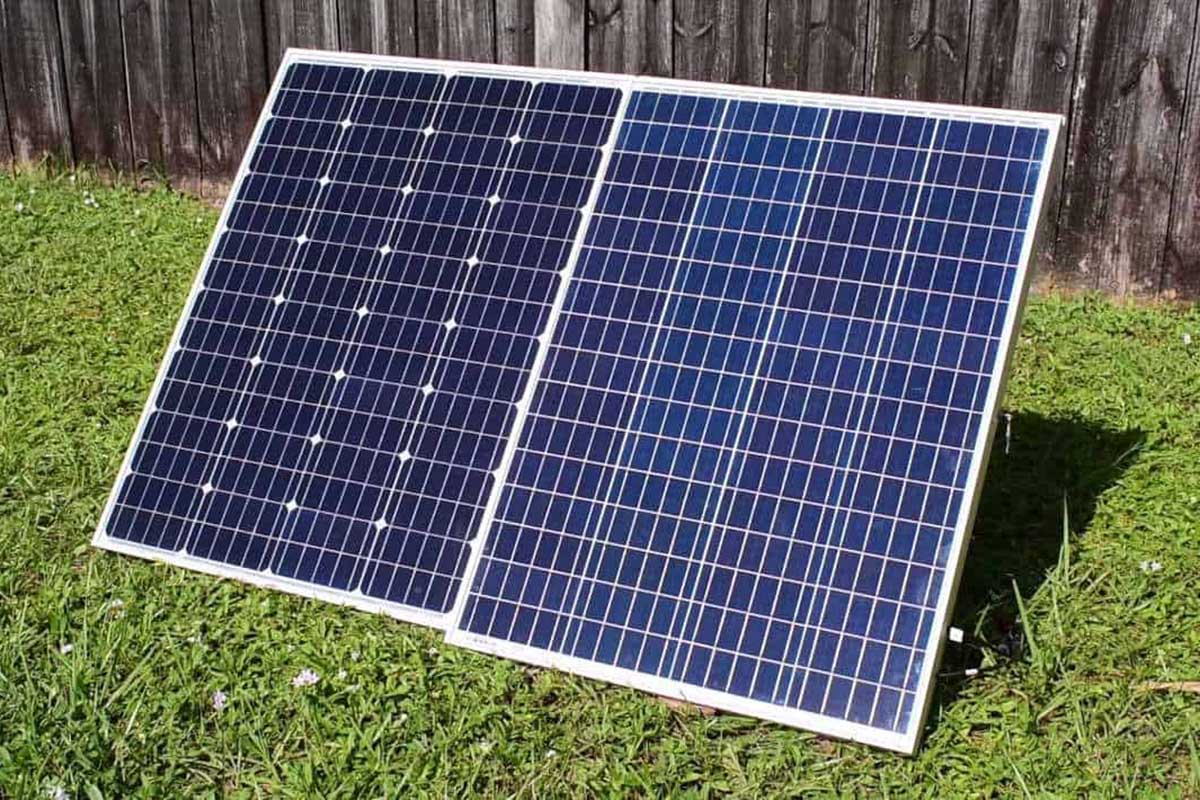
Standard monocrystalline panels usually use a white Backsheet, causing a distinct white diamond or square grid pattern to appear between the dark blue-black cell cells, looking like a giant chessboard from afar.
To pursue minimalist esthetics, manufacturers introduced module configurations known as "Triple Black":
1. Black Cells: utilizing the natural black crystal structure of monocrystalline silicon, combined with anti-reflective coating, to absorb over 95% of visible light and eliminate reflection.
2. Black Backsheet: Replacing the traditional white polymer backsheet with a black one. This change eliminates the color contrast in the cell gaps, making the entire panel visually connect into a deep whole, no longer disjointed.
3. Black Frame: Abandoning the generic silver aluminum alloy frame in favor of Black Anodized aluminum alloy.
Goodbye Ugly Silver Lines
Traditional panel surfaces have 5 to 12 thin silver lines for collecting current. Under sunlight, these silver lines glisten, destroying the overall black texture.
High-end monocrystalline technology hides these lines through process improvements:
· IBC Technology (Interdigitated Back Contact): Manufacturers move all electrodes and wiring to the back of the cell cells. The panel front has absolutely no metal lines, just a pure black glass surface.
· Shingled Cells Technology: Overlapping cell cells like roof tiles, using conductive adhesive instead of metal ribbons. This structure eliminates gaps between cells and blocks most metal connections, making the panel surface look like a single continuous piece of material.
Handling Picky HOAs
In the US, one of the biggest obstacles homeowners face when installing solar is often not budget, but the Homeowners Association (HOA).
Many HOAs have strict Covenants, Conditions, and Restrictions (CC&Rs) regarding community appearance, prohibiting facilities deemed "eyesores" or "destroying community uniformity."
Old-style blue poly panels, due to uneven color and severe reflection, are frequently rejected by HOAs on grounds of "causing visual pollution" or "producing glare."
All-black monocrystalline panels are a weapon for passing HOA approval:
· Low Glare: The matte black surface greatly reduces sunlight reflection, causing no light pollution for neighbors or streets.
· Low Profile: All-black panels blend quickly into the background, no longer standing out. Often, the HOA committee struggles to even detect that a PV system has been installed on the roof.
Blending with Shingles
The vast majority of US homes use Asphalt Shingles, with mainstream colors being Charcoal, Dark Gray, or Black.
Installing all-black monocrystalline panels on such roofs can achieve a "Pseudo-embedded" visual effect.
Although the panels are actually Rack-mounted, because the color matches the shingles highly, and modern mounting racks are extremely low-profile, the panels seem to be inlaid inside the roof.
Visual Comparison | Blue Poly Panel (Silver Frame) | All-Black Mono Panel (Black Frame) |
Distant View | Obvious blue patches, clashing with roof color | Almost invisible, not intrusive, adds texture instead |
Frame Visibility | Silver lines outline every panel | Black frames blend into shadows, no boundaries between panels |
Accessory Integration | Silver rails and clamps clearly visible from the side | Matching black clamps and End Caps hide metallic luster |
For certain high-end homes using dark cement tiles or Slate, this color consistency is mandatory; any other panel color would destroy the home's original classical or modern architectural style.
Easier to Sell the House without Devaluation
According to surveys by the National Association of Realtors (NAR), homebuyers are willing to pay a premium for homes with solar systems, but there is a premise: the system must look good and be well-maintained.
A messy, intrusive blue panel system might even have the opposite effect, making potential buyers feel they need to spend money to remove or renovate it.
Conversely, a well-designed all-black monocrystalline system is seen as a "high-tech upgrade," similar to a kitchen renovated with high-end black stainless steel appliances.
This esthetic advantage ensures your home remains competitive in the resale market, avoiding price suppression by buyers due to appearance issues.
Climate Adaptability
The power temperature coefficient of ordinary monocrystalline panels is typically between -0.34%/°C and -0.38%/°C, while N-type TOPCon or Heterojunction (HJT) technology can be as low as -0.26%/°C.
Compared to polycrystalline silicon (about -0.45%/°C), high-efficiency monocrystalline panels can retain 3% to 5% more rated power when the panel temperature reaches 65°C in summer.
Furthermore, monocrystalline modules generally pass 5400Pa front snow load and 2400Pa rear wind load tests, combined with salt mist resistance certification (IEC 61701), enabling adaptability to various extreme environments from high-heat deserts to high-humidity coasts.
Output Under High Temperatures
Relationship Between Voltage and Temperature
Although high temperatures can slightly increase electron activity (slightly boosting current, Isc), they significantly narrow the "Band Gap" of the silicon material.
The direct consequence of a shrinking band gap is a significant drop in Open-Circuit Voltage (Voc). For standard crystalline silicon cells, voltage drops by about 2mV to 3mV for every 1°C rise in temperature.
· Impact of Voltage Drop: Power equals voltage times current (P = V x I). When current is nearly unchanged but voltage drops significantly, total power naturally decreases.
· Advantage of Monocrystalline Silicon: High-purity monocrystalline silicon lattices are neatly arranged with few internal impurities. Compared to polycrystalline silicon, monocrystalline silicon (especially N-type cells) has a stronger ability to maintain stable voltage under high temperatures, which is directly reflected in a lower "Power Temperature Coefficient."
Temperature Coefficient
It indicates what percentage of output power is lost for every 1°C rise after the panel temperature exceeds Standard Test Conditions (STC, i.e., 25°C).
Differences in coefficients between technology routes are distinct:
Panel Technology Type | Typical Temperature Coefficient | Heat Loss Description |
Polycrystalline Silicon | -0.40% / °C to -0.50% / °C | Worst heat resistance, fast power loss at high temperatures. |
Ordinary Mono P-PERC | -0.34% / °C to -0.38% / °C | Current market mainstream, average performance. |
Mono N-TOPCon | -0.29% / °C to -0.32% / °C | Excellent heat resistance, suitable for high-temperature areas. |
Mono Heterojunction (HJT) | -0.25% / °C to -0.27% / °C | Superb heat resistance, almost approaching thin-film panel performance. |
Data Example:
Assume two panels nominally rated at 400W, one is ordinary poly (coefficient -0.45%), the other is high-efficiency mono HJT (coefficient -0.26%).
At noon in summer, when panel surface temperature reaches 65°C (40°C higher than STC standard):
· Poly Panel Loss: 40 x 0.45% = 18%. Actual output only 328W remaining.
· Mono HJT Panel Loss: 40 x 0.26% = 10.4%. Actual output still 358.4W.
The monocrystalline panel generated 30W more electricity at this moment; this gap accumulates into a huge difference in power generation throughout the summer.
Cell Operating Temperature
Dark solar panels absorb heat. On days with strong sunlight and no wind, the actual temperature of the cells is usually 25°C to 35°C higher than the surrounding air temperature.
If in Arizona or Nevada, where ambient temperature reaches 40°C (104°F), solar panel temperatures on roofs can easily breach 75°C.
Under such extreme operating conditions, the material properties of high-efficiency monocrystalline panels come into play:
1. Lower Thermal Resistance: Premium monocrystalline modules typically use encapsulation materials with better thermal conductivity (like POE film) and backsheets, helping heat dissipate from the back of the cell cells.
2. Anti-LeTID Degradation: Many P-type monocrystalline or polycrystalline panels suffer from "Light and elevated Temperature Induced Degradation" (LeTID) under the dual action of high temperature and light, causing permanent power loss. N-type monocrystalline silicon is doped with Phosphorus instead of Boron, chemically naturally immune to this high-temperature degradation caused by Boron-Oxygen complexes, ensuring full life-cycle stability.
Heat Dissipation of Half-Cut Technology
Modern high-efficiency monocrystalline panels generally adopt Half-cut Cell Technology.
Manufacturers use lasers to cut standard 182mm or 210mm cells in half.
This physical change is not just for esthetics but primarily to control heat:
· Halved Current: According to Joule's Law, heat loss is proportional to the square of the current (Q = I²R). Cutting the cell in half reduces operating current by half, lowering heat loss generated by internal resistance to 25% of the original.
· Lower Operating Temperature: Measured data shows that under identical conditions, the average operating temperature of half-cut mono modules is 2°C to 3°C lower than full-cell modules.
Power Generation in Low Light Environments
It's Not Just Direct Light That's Useful
When clouds block the sun, Direct Irradiance is indeed blocked, but "Diffuse Irradiance" still exists.
Clouds act like a giant softbox; although they filter out some long-wavelength red light and infrared rays, penetration remains strong in the short-wavelength blue and violet bands.
· The Shortcoming of Polycrystalline: Traditional polycrystalline silicon has a chaotic crystal structure with massive recombination centers at grain boundaries.
· Broad Spectrum Capture of Monocrystalline: High-purity monocrystalline silicon, especially panels introducing Heterojunction (HJT) or TOPCon technology, has a wider spectral response range.
Waking Up Early, Sleeping Late
PV inverters have a hard "Start-up Voltage" threshold. Only when the sum of the module string voltage exceeds this threshold will the inverter wake up and start working.
At sunrise, light is extremely weak:
1. Ordinary Panels: Due to lower internal Shunt Resistance, photo-generated current "leaks" inside the cell, causing voltage to climb slowly. It might take until 8:30 AM, when sunlight reaches 400 W/m², for the voltage to be sufficient to start the inverter.
2. High-Efficiency Monocrystalline Panels: Extremely high internal shunt resistance ensures that even with weak photo-generated current, high open-circuit voltage can be maintained. They might wake up the inverter and start exporting power to the grid as early as 7:45 AM, when sunlight is only 200 W/m².
Cruel Test at 200W/m²
The PV industry typically uses an irradiance of 200W/m² (only one-fifth of the standard 1,000W/m²) to simulate typical cloudy or dawn/dusk environments.
Theoretically, if light reduces by 80%, power should also reduce by 80%, keeping efficiency unchanged.
But in reality, as light intensity weakens, due to the effect of parasitic resistance, the conversion efficiency of most panels drops sharply.
Technology Type | Relative Efficiency Performance at 200W/m² | Explanation |
Standard Poly Silicon | Drops 3% - 5% | When light gets weaker, its ability to convert light energy also gets weaker (double blow). |
Ordinary Mono PERC | Drops 0% - 2% | Stable performance, basically maintains nominal efficiency. |
N-Type TOPCon / HJT | Increases 0% - 1% | Surprising counter-intuitive phenomenon: in weak light, the relative efficiency of some high-efficiency mono panels is actually higher than in strong light. |
Microscopic Game of Parasitic Resistance
To deeply understand the weak light advantage, we must discuss two microscopic parameters of cell cells: Series Resistance (Rs) and Shunt Resistance (Rsh).
In strong light, current is like a raging flood, mainly affected by Series Resistance (the width of the channel).
But in weak light, current is like a trickle, and at this time Shunt Resistance (whether the dyke leaks) becomes crucial.
· Low-Quality Cells (Low Rsh): Like a water pipe full of cracks. When water flow (photo-current) is small, most water leaks directly through cracks (crystal defects) and never reaches the tap (output end).
· High-Efficiency Mono (High Rsh): Perfect lattice structure, using high-quality edge passivation processes, blocking channels for electron leakage.
Tilt Angle and Incident Light Loss
Weak light performance is also related to the optical properties of the panel glass, involving the "Incidence Angle Modifier" (IAM).
In the early morning and evening, sunlight strikes the panel glass at a very large oblique angle.
Ordinary glass acts like a mirror, reflecting most of the obliquely incident light back to the sky instead of letting it enter the cell cell.
High-end monocrystalline module manufacturers use advanced Anti-Reflective Coating and special surface light-trapping textures on tempered glass.
1. Light Trapping Action: This texture causes "secondary refraction" of large-angle incident light on the glass surface, forcibly changing the light path and guiding it into the cell cell.
2. Actual Gain: In high-latitude areas in winter, the sun is in a low-angle position all day. Monocrystalline panels with excellent IAM performance can capture more than 5% more oblique light energy than ordinary panels.
Wind and Snow Load Capacity
Snow is Not Just Weight, It's Pressure
During the slight warming process after severe cold, accumulated snow melts and refreezes, forming a highly dense mixture of ice and snow.
· Dry Snow: Density approx. 100 kg/m³.
· Wet Snow/Ice: Density can reach 500 to 800 kg/m³.
The industry standard IEC 61,215 stipulates a basic test load of 5400 Pascal (Pa).
Each square meter of panel surface must withstand a weight of about 550 kg. For a standard 2-square-meter residential monocrystalline panel, this is equivalent to a small car pressing on it.
High-end monocrystalline manufacturers (such as REC or Maxeon) realize that 5400 Pa might be a critical value in some extreme blizzard years, so they often raise internal test standards to 7000 Pa or even higher.
Invisible Cracks are the Big Trouble
Compared to visible glass breakage, Micro-cracks are a more hidden threat.
When the panel bends under pressure, although tempered glass has some elasticity, the silicon wafer sandwiched in the middle is very brittle.
If the bending amplitude exceeds physical limits, invisible fine cracks will occur inside the silicon wafer.
1. Characteristics of Polycrystalline: Grain boundaries are originally discontinuous, crack propagation is relatively disordered, and the impact on power is unpredictable.
2. Characteristics of Monocrystalline: Crystal structure is perfectly unified. Once stressed to crack, it often cuts through the entire cell cell.
3. Consequences: Problems may not be visible initially, but with thermal expansion and contraction, cracks widen, forming "Dead Zones," causing local resistance to rise sharply, generating Hot Spots, and eventually burning the backsheet.
To solve this problem, modern high-efficiency monocrystalline modules usually use Multi-Busbar (MBB) or Shingled technology.
Even if the cell develops micro-cracks due to heavy pressure, the dense network of metal grid lines acts like "stitches," building conductive bridges to ensure current can still bypass the cracks and flow out, controlling power loss within 1%.
Wind Sucks the Panels Up
In windy weather, solar panels face not only frontal thrust but, more dangerously, "suction" from the back.
According to Bernoulli's principle, when airflow moves rapidly over the roof and panel surfaces, the slower airflow on the back of the panel (the side closer to the roof) creates a pressure difference.
This force tries to uproot the panel from the bracket. This is called Negative Load or Wind Uplift.
IEC standards require the back to withstand a pulling force of 2400 Pa.
This roughly corresponds to a wind speed of 130 mph (about 210 km/h), equivalent to a Category 3 or 4 hurricane.
However, in actual installations, especially for systems installed at a tilt on flat roofs, wind pressure in edge areas multiplies.
· Reinforced Frames: Cheap panels use 30mm or 35mm high aluminum frames. High wind load resistant monocrystalline panels typically use 40mm or even 46mm 6005-T6 anodized aluminum alloy frames designed with a double-layer Hollow Chamber structure.
· Torsional Resistance: This thickened design greatly enhances torsional stiffness, ensuring that the panel does not flutter like a piece of paper during violent vibrations caused by strong winds, thereby protecting internal cell connection points from fatigue fracture.
Physical Advantages of Double Glass Structure
To completely solve mechanical stress problems, many N-type TOPCon or HJT monocrystalline panels adopt Double Glass encapsulation technology.
The traditional panel structure is: Glass + Cell + Plastic Backsheet.
Double glass panel structure is: 2.0mm Glass + Cell + 2.0mm Glass.
This symmetrical sandwich structure introduces a very important concept in mechanics: Neutral Axis.
· When a single-glass panel bends under pressure, the cell cell is on the side being stretched and breaks easily.
· When a double-glass panel bends under pressure, because the stiffness of the upper and lower materials is consistent, the cell cell is located exactly at the "Neutral Axis" of the force. Here, the cell cell is neither stretched nor compressed, and is almost unaffected by stress.
Data shows that after the same 5400 Pa snow load test, the micro-crack rate of double glass monocrystalline modules is more than 80% lower than that of traditional single glass modules.