Bifacial Monocrystalline Panels | Pros, Cons and Application Scenarios
Bifacial monocrystalline modules, in high-reflection scenarios such as snow or white-painted ground, can achieve a rear-side generation gain of 5% - 30%.
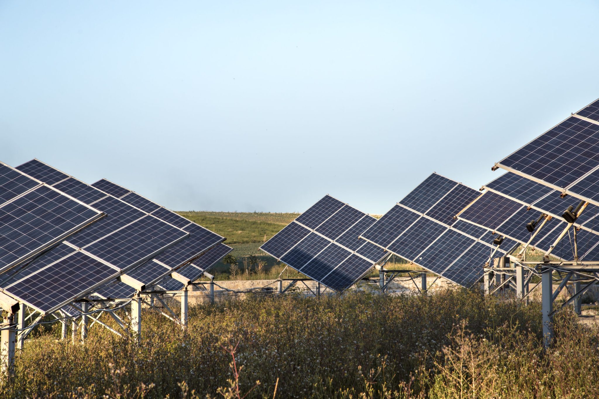
Installation requires raising the racking height and avoiding rear shading.
Although the initial cost is slightly higher, it is the preferred solution for large-scale ground-mounted power stations to reduce the Levelized Cost of Electricity (LCOE).
Pros
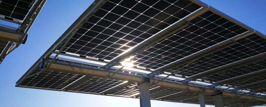
Bifacial monocrystalline modules absorb ground-reflected light (Albedo) and environmental scattered light through the glass or transparent backsheet on the rear side, generating an additional 5% to 30% power gain.
The magnitude of this gain depends on the ground reflectivity; for example, it peaks on snow or white roofs.
Due to the predominant adoption of the Dual-Glass (Glass-Glass) structure, these modules typically come with a 30-year linear power warranty, which is 5 years longer than traditional single-sided modules.
Their annual degradation rate is typically lower than 0.45% (compared to 0.55% for traditional modules), and the zero water permeability of glass significantly reduces the risk of PID (Potential Induced Degradation) and snail trails, giving them a superior advantage in total power generation (LCOE) over their lifecycle.
Rear Side Gain
Albedo determines the upper limit
Different ground surface materials have vastly different albedos, directly leading to generation gains ranging from 5% to 30%.
Data indicates that only when the albedo is higher than 15% - 20% can the additional equipment investment (such as bifacial module costs and specialized racking) be covered by the generation revenue.
The following are reference data for measured albedo of common ground surface materials:
Ground Material Type | Albedo Range | Estimated Rear Generation Gain |
Fresh Snow | 80% - 90% | > 25% - 30% |
White TPO/EPDM Roof | 70% - 80% | > 20% - 25% |
Dry Sand / Light Soil | 25% - 35% | 8% - 12% |
Grass (Green) | 15% - 25% | 6% - 8% |
Old Concrete / Cement | 20% - 30% | 7% - 10% |
Dark Asphalt / Wet Soil | 10% - 15% | < 5% (Low Return) |
Note: Over time, white roofs will accumulate dust and become dirty, with albedo typically dropping by 10% - 15% two years after installation. When calculating 25-year lifecycle revenue, one cannot rely solely on the initial albedo but must input a degradation curve from high to low.
Engineering data on mounting height
If the module is installed close to the ground, the rear side will not only be blocked by the module's own shadow, but the angle of light entering the rear (View Factor) will also be restricted.
However, infinitely increasing the racking height will significantly increase steel costs and wind load risks.
According to PVsyst simulations and field data from the NREL laboratory in the US, there is a critical point of diminishing returns:
· 0.2m - 0.5m: The rear side receives severely uneven light, and the gain is very limited, usually below 4%. Being low to the ground not only means less light but also makes it easy to be blocked by ground vegetation.
· 0.5m - 1.0m: This is the range where gains increase the fastest. Increasing the height from 0.5m to 1.0m typically brings an additional 2% - 3% system efficiency boost on grass.
· 1.0m - 1.5m: The revenue curve begins to flatten. The extra power generation from continuing to increase height often struggles to cover the increased costs of steel and manual installation.
· Optimal Balance Point: For most ground-mounted power stations, 1.0m to 1.2m (distance from the lowest point of the module to the ground) is currently the most economically optimal height setting.
Impact of row spacing
In traditional single-sided module stations, the design of row spacing (Pitch) mainly considers avoiding shading the front row at 9 AM on the winter solstice.
But in bifacial module systems, if the arrangement is too dense, a "self-shading" effect occurs.
Here is a specific engineering metric: GCR (Ground Coverage Ratio).
· Single-sided module stations usually have a GCR designed around 50%.
· For bifacial module stations, to let more light hit the ground and reflect, it is recommended to lower the GCR to 35% - 45%.
· Data tests show that at the same height, widening the row spacing by 1 meter can increase rear irradiance by 5% - 10%, but this requires weighing against land lease costs.
Rear shading caused by racking structure
The racking structure itself casts shadows on the back of the module, known as "rear structure shading loss."
1. Purlin/Beam Shading:
If traditional racking beams cross directly behind the module, they will block 3% - 5% of the cell area. Since cells are connected in series, shading a small part can cause the current of the entire cell string to drop. Modern bifacial-specific racking typically uses an "avoidance design," fixing only at the module frames or using specially designed narrow-section rails to control shading loss within 1% - 1.5%.
2. Junction Box Location:
To reduce shading, the Junction Box of bifacial modules is usually split into three small independent boxes located at the edges of the module, rather than a large block concentrated in the middle like traditional modules. This design increases the rear light-receiving area by about 0.5%.
3. Difference between 1P and 2P Trackers:
When using trackers, the torque tube (main axis) of a 1P (One-in-Portrait) structure is usually located directly behind the module. If the main axis is a round or square tube, a gap of at least 100mm - 150 mm (Torque tube gap) must be maintained from the module back, otherwise, it causes severe shading and creates local hot spots. In contrast, 2P (Two-in-Portrait) structures usually have a gap between the two rows of modules, so the main axis does not directly shade the cells, and rear optical performance is generally superior to 1P structures.
Mechanical Performance
Structural change from single glass to double glass
Traditional single-sided modules typically use 3.2mm photovoltaic glass plus a layer of polymer backsheet.
Bifacial modules currently mostly use a configuration of 2.0mm + 2.0mm dual-sided semi-tempered or fully tempered glass.
Although the two layers of glass combined are only 0.8 mm thicker than the original, this symmetrical "sandwich" structure changes the physical model of the module under load.
The Young's Modulus (a measure of material stiffness) of glass is about 70 - 75 GPa, whereas traditional plastic backsheets are only 2 - 4 GPa.
Cells located in the "Neutral Layer"
When a module bends downward due to wind or snow pressure, the surface endures compression, while the bottom endures tension.
· Traditional Modules: Since the front is hard glass and the back is soft backsheet, the center of force (neutral layer) shifts towards the glass side. The silicon cells located underneath endure immense Tensile Stress. Silicon wafers are very brittle and prone to micro-cracks when stretched.
· Bifacial Dual-Glass Modules: Since both front and back are 2.0mm glass, with completely symmetrical material and thickness, the "neutral layer" falls exactly between the two layers of glass—which is where the cell cells are located. According to mechanics, the neutral layer endures almost neither tension nor compression during bending.
Laboratory data shows that under the same 5400 Pa load, the stress endured by cells in bifacial modules is typically 40% - 50% lower than in traditional modules.
Ultimate load capacity
In IEC 61215 standard tests, modules need to withstand 2400 Pa wind load (equivalent to 130 km/h wind speed) and 5400 Pa snow load (equivalent to about 550 kg of snow per square meter).
Due to the high structural strength of bifacial dual-glass modules, many tier-1 manufacturers' products can even pass 7200 Pa or higher static load tests on the front side without glass breakage in internal stricter tests.
For Nordic or North American regions where extreme blizzards are frequent due to climate change, this mechanical redundancy is very practical.
Moreover, the back of bifacial modules is also glass, giving it stronger "rear wind resistance."
In certain installation scenarios (such as high racking or array edges), rear wind pressure can instantly exceed 2400 Pa.
Traditional backsheets might tear or suffer fatigue delamination, while dual-glass structures can handle it with ease.
Physical defense against hail and sand
The Mohs Hardness of glass is around 6.5, far higher than any polymer backsheet. This gives bifacial modules natural impact resistance.
· Hail Tests: Standard tests require modules to withstand a 25 mm diameter ice ball hitting at 23 m/s (about 82 km/h). In reality, dual-glass modules can usually pass more rigorous tests, such as 35mm or even 45mm hail impact tests.
· Sand Abrasion: In the Middle East or US Southwest desert regions, continuous sand blowing acts like a sandblaster. Ordinary backsheets will thin, become brittle, and eventually lead to insulation resistance failure under perennial sand erosion. Glass, being an inorganic material, hardly loses thickness due to sand abrasion, ensuring electrical insulation safety for 30 years or more.
Long Lifespan
Natural advantage of inorganic materials against UV
To understand why bifacial dual-glass modules can last 5 years longer or more, one must look at the nature of the materials.
The protective layer on the back of traditional single-sided modules is a Polymer Backsheet, usually laminated from organic plastics like PET, PVDF, or Tedlar.
Even the highest-grade fluorine-containing backsheets will have their polymer chains gradually broken by high-energy photons from ultraviolet (UV) rays after 20 years of sun exposure.
This photodegradation leads to yellowing, embrittlement, and even chalking and cracking of the backsheet.
Once the backsheet cracks, electrical insulation fails, leading to leakage risks.
In contrast, the Photovoltaic Glass on the back of bifacial modules is an inorganic material (primarily silicon dioxide).
The bond energy of silicon-oxygen bonds is extremely high, and UV energy is insufficient to break them.
No matter how many years it is exposed to intense UV, the light transmittance and physical strength of glass remain almost unchanged.
This is why we see 50-year-old glass windows still intact outdoors, but rarely see plastic sheets that remain tough after 20 years.
Blocking moisture penetration and acetic acid corrosion
Water vapor is the biggest driver of PV module aging.
· Water Vapor Transmission Rate (WVTR) Comparison:
Although high-quality polymer backsheets look waterproof, they are breathable at a microscopic level. Their WVTR is typically between 1 g/m²/day and 3 g/m²/day.
· Acetic Acid Formation and Corrosion:
When water vapor penetrates the backsheet and enters the module, it reacts with the encapsulant film (EVA, Ethylene-Vinyl Acetate) via hydrolysis. This reaction releases Acetic Acid (Vinegar). Acetic acid is a corrosive agent that slowly corrodes the silver grid lines and ribbons on the cell surface, increasing series resistance (Rs) and ultimately causing a significant drop in power.
Encapsulant Material Upgrade: From EVA to POE
To accommodate bifacial generation characteristics and ensure a 30-year lifespan, bifacial modules have also undergone a passive upgrade in encapsulation materials.
Since glass is non-breathable, if traditional EVA film is used in a dual-glass structure, decomposition products during lamination cannot be expelled, causing bubbles.
Therefore, current high-quality bifacial modules (especially N-type TOPCon and HJT) universally adopt POE (Polyolefin Elastomer) or EPE (EVA-POE-EVA co-extrusion) films.
POE film has two decisive lifespan advantages over traditional EVA:
1. Higher Volume Resistivity: POE's insulation performance is 1 to 2 orders of magnitude higher than EVA, which is particularly evident in high-temperature and high-humidity environments.
2. Chemical Inertness: POE molecular chains do not contain polar groups and will not decompose to release acidic substances like EVA does.
Data Differences in Degradation Curves
The industry uses the Annual Degradation Rate to quantify this metric.
The standard degradation model for traditional single-sided modules is typically: 2% in the first year, followed by 0.55% annually.
Bifacial dual-glass modules, especially those combined with N-type cell technology, typically promise: 1% in the first year, followed by 0.40% or even 0.35% annually.
Do not underestimate this 0.15% gap; over a 30-year span, the difference is massive:
Year | Traditional Single-Sided Module (P-type Backsheet) Remaining Power | Bifacial Dual-Glass Module (N-type Bifacial) Remaining Power |
1 Year | 98.0% | 99.0% |
10 Years | 93.0% | 95.4% |
20 Years | 87.5% | 91.4% |
25 Years | 84.8% (Warranty usually ends) | 89.4% |
30 Years | No Warranty (Estimated < 82%) | 87.4% |
In year 30, bifacial modules can still maintain over 87% of their factory generation capacity, which directly extends the asset's cash flow generation period in financial models.
Anti-PID (Potential Induced Degradation) Performance
In 1500 V high-voltage DC systems, a huge potential difference exists between the cells and the grounded frame.
This drives sodium ions in the glass to move or causes carrier recombination on the cell surface, leading to power degradation, known as the PID phenomenon.
Bifacial dual-glass modules have structural advantages in PID resistance:
1. Frameless or Insulated Treatment: Many dual-glass modules use frameless designs, or better insulation between the frame and glass, cutting off leakage current paths.
2. Blocking Humidity: PID effects are often exacerbated in high-temperature, high-humidity environments. As mentioned, the dual-glass structure completely blocks moisture entry, suppressing PID conditions from environmental factors.
3. Encapsulant Film: Using the high-impedance characteristics of POE film further reduces leakage current to the microampere (uA) level, keeping PID degradation within 2% even under rigorous test conditions of 85°C and 85% humidity.
Cons
Compared to single-sided modules, the per-watt cost of bifacial products is typically 1-3 cents higher, and specialized racking to avoid rear shading increases installation costs by 5-10%.
The most significant constraint lies in Ground Reflectivity (Albedo): if installed on asphalt or dark soil (reflectivity <10%), the rear generation gain is extremely low and cannot offset the initial investment.
Additionally, the dual-glass structure brings the average module weight to 25-30 kg, limiting its application on older roofs with weak load-bearing capacity.
Reliance on Ground Reflection
Albedo is money, but it's hard to earn
The "Albedo" input in PV system simulation software (like PVsyst) is usually a fixed number, but in actual operation, this value is an uncontrollable variable.
If the project site's ground reflectivity is below 15%, the extra electricity generated by bifacial modules is usually insufficient to cover the hardware premium (CAPEX) of 0.01-0.03 USD/Watt over single-sided modules.
Common Inefficiency Traps:
· Dark Asphalt & Old Concrete: Many commercial roofs use dark gray waterproofing layers with reflectivity of only 4% to 9%. In this context, the additional power output from the rear may be only around 1%, which is basically negligible.
· Common Soil & Dry Grass: Standard soil reflectivity is around 15%, which is just the break-even line.
Contradiction between Module Height and "View Factor"
There is a pure geometric limitation here, known in engineering as the View Factor.
How much ground the back of the module can "see" directly determines how much light it can receive.
· Too close to the ground is fatal: As long as the gap between the module and the ground (or roof) is less than 1 meter, the reflected light received by the rear drops sharply.
· Self-Shading Effect: The module itself blocks direct sunlight from hitting the ground directly below it. If the installation height is too low (e.g., 0.4m - 0.5m), there will always be a black shadow band directly below the module.
Data Comparison:
In the same grass environment (20% reflectivity):
· Installation height 1.2 m: Rear gain may reach 7% - 9%.
· Installation height 0.5m: Rear gain will plummet to 2% - 3%.
Too dense arrangement ruins the rear side
To install more watts on limited land, PV plants often pursue a high GCR (Ground Coverage Ratio). But this is mutually exclusive with bifacial generation.
· Blocked Light Path: If the front and rear rows of modules are too close (narrow row spacing), sunlight can hardly shine on the ground between the two rows. If the ground receives no direct light, naturally there is no light energy to reflect back to the module.
· Data Quantification: When GCR exceeds 0.5 (i.e., modules cover 50% of the land area), bifacial gain begins to decay significantly.
· Economic Calculation: Developers face a dilemma—widen the row spacing (wasting land rent) for rear gain? Or narrow the spacing (saving land) but sacrifice bifacial effects? On expensive land, the advantage of bifacial modules gets wiped out by high land prices.
Invisible costs of environmental aging and O&M
That white TPO roof set to "70% reflectivity" in the design phase will definitely not be white two years later.
· Natural Soiling: Exposed white waterproofing membranes or white gravel will turn gray due to dust settlement, rain stains, tire marks, and mold growth.
o Measured Data: A newly laid white roof (75% reflectivity) typically sees its reflectivity drop to 40% - 50% within two years without special cleaning.
· Ground Must Be Cleaned: To maintain the calculated Rate of Return (IRR), the O&M team must clean not only the modules but also the roof or ground.
Hardware discount of Bifaciality
Cell technology dictates that the rear side is always weaker than the front.
This is called the Bifaciality Factor.
· PERC Cells: Currently the largest stock in the market, their rear efficiency is usually only about 70% of the front. Even if you expose the back to sunlight as strong as the front (physically impossible), it only generates 70% of the electricity compared to the front.
· TOPCon Cells: Slightly better, reaching 80% - 85%.
· HJT Cells: Can reach over 90%, but are expensive.
If you use standard PERC bifacial modules, combined with ordinary grass (20% reflectivity), plus racking shading and angular losses, the rear gain reaching the inverter is often only 5% - 7%.
High Racking Costs
The back must not be blocked, which costs extra
The logic of bifacial modules is simple: let there be light on the back. But traditional racking design logic is completely the opposite.
In standard single-sided module installations, the most economical method is to use two long horizontal rails directly traversing the back of the module.
This method is fast and uses minimal aluminum, making it the cheapest. But if this racking is used on bifacial modules, these two beams will directly block the rear cells.
· Double Hit from Shading:
o Direct Generation Loss: Areas blocked by beams cannot generate electricity at all.
o Hot Spots Risk: Cells blocked by racking for a long time become loads, consuming current generated by other cells, leading to local overheating and even glass breakage.
To solve this, you must buy racking systems specifically designed for bifacial modules. Such systems usually use "frame mounting" or only longitudinal beams, ensuring the area directly behind the module is empty.
· Hardware Premium: This specialized racking structure is more complex, usually 10% to 15% more expensive than universal racking.
· Additional Accessories: Extra clamps and spacers are needed to ensure the PV panel is suspended above the racking beams to avoid contact shading. Every extra metal part adds to the BOM (Bill of Materials) cost.
Piles must be longer, steel usage skyrockets
To let ground reflected light crawl under the modules, bifacial modules must be raised higher.
· Height Determines Light Quantity: The lowest ground clearance (Leading Edge Height) for standard single-sided ground stations is usually set around 0.5 meters, mainly for flood prevention and splash protection. But for bifacial modules to get decent rear gain, the clearance must reach at least 1.0 meter or even 1.2 meters.
· Mechanical Leverage Effect: Lifting an array of hundreds of tons of modules by half a meter has a huge impact on the Moment (Torque) on the racking piles.
o When the module position rises, the lever arm for wind force increases, doubling the stress at the root.
o To resist this stronger overturning moment, racking piles must use thicker steel (e.g., increasing wall thickness from 2.5mm to 3.0mm or 4.0mm).
o Pile driving depth also needs to increase. If the soil is soft, it might require switching from driven piles to independent concrete foundations, causing Civil Works costs to soar by over 20%.
Wind resistance design is harder, especially in windy areas.
Most bifacial modules use dual-glass structures, heavier than traditional backsheet modules, and the glass surface is smoother than plastic backsheets with a lower friction coefficient.
· Slippery Glass: Traditional aluminum clamps rely on friction to grip module frames. But in high wind pressure areas, dual-glass modules are more prone to sliding out of clamps due to their own weight and smooth characteristics.
· Reinforcement Costs: Structural engineers usually require special clamps with anti-slip teeth or increasing the number of clamps (e.g., from standard 4-point fixing to 6-point fixing). Two extra fixing points per module means hundreds of thousands of extra metal parts and corresponding labor hours for a 100MW plant.
· Galloping Effect: Bifacial modules are widely used on trackers. Due to high installation height and open rear, vortices formed by airflow behind the module are more complex. To prevent destructive galloping on windy days, the racking system needs more Dampers or stiffeners, which are extra expenses not needed for single-sided systems.
"Torque Tube" avoidance fees for trackers
The currently recognized best combination is "Bifacial Modules + Trackers," as trackers keep modules at optimal angles all day while also increasing ground reflected light.
But on single-axis trackers (1P or 2P structures), the thick main axis (Torque Tube) in the middle is a huge obstruction.
· Distance Creates Beauty, and Bills: If modules are installed tight against the main axis, the axis casts a 10-15 cm wide shadow on the back. To avoid this, special Gap Brackets or Tube Clamps must be installed between the module frame and the main axis to elevate the module, allowing light to bypass the axis and hit the back.
· Installation Precision Requirements: This elevated structure increases installation complexity. Workers need to align more bolt holes, slowing installation efficiency by about 15% compared to direct flush mounting.
Cables can't be tossed around, wire management costs money
In single-sided module plants, Wire Management is relatively crude. Cables are often zip-tied casually to the beams behind the module or even hung directly behind it.
But in bifacial systems, this doesn't work.
· Shadow Allergy: Even a thin PV cable crossing the back of a module acts like a sundial pointer, casting a moving shadow on cells all day. This causes severe current Mismatch.
· Routing Must Detour: Cables must run along the metal frame of the module, strictly hiding in the frame's shadow, or be concealed in specially designed Trunking.
· Cost Quantification:
o Need to buy more stainless steel Cable Clips; plastic zip ties are usually not allowed due to short life and tendency to loosen/shift.
o Because cables must route around frames at right angles, the total usage of DC Cable is usually 5% - 8% higher than in single-sided systems.
o Electrician wire management time doubles. Under strict acceptance standards, no hanging cables are allowed to be seen on the back, which consumes immense labor hours.
Application Scenarios
In snow or white TPO roof environments where reflectivity exceeds 80%, rear generation gain can reach 20%-30%;
Whereas in ordinary grass or soil environments (reflectivity 15%-25%), the gain typically stabilizes at 5%-10%.
To maximize the performance of PERC or TOPCon cells, installation design must meet a minimum ground clearance of 1 meter and prioritize racking systems without rear shading to ensure scattered light can smoothly enter the back of the module.
High Albedo Ground Plants
Snow environment is a natural reflector
The reflectivity of fresh dry snow stabilizes between 80% and 90%. In this environment, the performance of PV systems is exaggerated.
· Low Temperature High Voltage Effect: PV cells fear heat, not cold. Snowy days are usually accompanied by low temperatures, and the open-circuit voltage (Voc) of silicon-based batteries rises as temperature drops (temperature coefficient usually -0.24%/C to -0.28%/C). "Extremely high ground reflection" plus "low-temperature environment" can allow bifacial modules to instantly output power exceeding 110% to 120% of their nameplate rating.
· Rear Snow Melting Function: Many worry about snow coverage. In fact, bifacial modules have a self-cleaning advantage in snow. When the sun rises in the morning, the back receives strong reflected light from the snow first and starts working and heating up. This heat conducts to the front, melting the bottom of the snow on the module surface into a water film. The snow slides off in chunks due to gravity. Test data from Minnesota or Northern Europe shows that bifacial modules lose 3% to 5% less generation annually due to snow compared to single-sided modules.
Spectrum and Red Light Reflection in Desert
Although sand reflectivity (25% - 35%) is far less than snow, desert environments have a special optical advantage: spectral red shift.
· Stronger Infrared Reflection: Light-colored sandy soil reflects longer wavelength light (red and near-infrared) more strongly than short wavelength (blue light). Crystalline silicon cells (whether PERC, TOPCon, or HJT) happen to have extremely high spectral response to the 700nm - 1100nm near-infrared band.
· Racking Shadow Control: Direct light is strong in deserts, making shadows sharp. If "2-Portrait (2P)" or "multi-row" racking is used, rear beam shadows will be very heavy. The trend is to use "1-Portrait (1P)" independent support structures and increase the distance between the Torque Tube and module backsheet to 100mm - 150mm, specifically to diffuse the shadow so it doesn't block the cells dead on.
Is it worth laying artificial white ground cover?
Some owners are not satisfied with natural ground and calculate whether buying white geotextile to cover the ground will pay off.
· Material Selection & Degradation: Common materials include Polypropylene (PP) woven fabric or white gravel. When freshly laid, reflectivity can reach 70%. But outdoor environments are dirty; after three months of dust coverage, reflectivity drops to 50% - 60%. In rainy areas, mud splashes can drop reflectivity back to around 40% after a year.
· ROI Data: According to field tests, raising reflectivity from 20% (soil) to 50% (old white cloth) artificially increases bifacial gain from 7% to 15%. If the electricity price is below 0.03 USD/kWh, laying ground cloth usually doesn't pay back, because the cost of material plus labor is about 0.01 - 0.02 USD/Watt, and the cloth only lasts 3-5 years before needing replacement.
Reflectivity and Lifespan Comparison of Common Surface Materials
Material Type | Initial Reflectivity | Expected Reflectivity after 1 Year | Maintenance Difficulties |
Fresh Dry Snow | 85% - 90% | N/A (Seasonal) | Must monitor if snow depth buries module bottom edge |
White Geotextile | 70% - 75% | 40% - 50% | Prone to tearing, weed growth, darkening from dust |
White Gravel/Crushed Stone | 50% - 60% | 40% - 50% | Easily sinks into soil, high laying cost |
Light Concrete | 40% - 50% | 35% - 40% | Extremely high cost, usually only for hardened areas |
Dry Sand | 30% - 35% | 30% - 35% | Airborne dust causes severe soiling on module surface |
Modules must be mounted higher than usual
In the single-sided module era, to save steel, racking was kept as low as possible. But in high-albedo ground plants using bifacial modules, the racking must "grow taller."
· View Factor: Imagine the back of the module has eyes. If it's too close to the ground (e.g., only 0.5m), these eyes can only see their own black shadow cast on the ground, not the distant ground illuminated by the sun.
· Golden Height 1.5m: Engineering data shows that when the module's lowest point (Clearance Height) is raised from 0.5m to 1.0m, rear radiation increases the fastest. After exceeding 1.5 m, the gain saturates, and raising it further only increases steel costs and wind load risks. Therefore, most projects utilizing high-reflectivity ground design their lowest point between 1.0m and 1.5m.
Inverter Ratio needs recalculation
High-albedo ground keeps modules in a high-power output state for long periods, affecting the DC/AC Ratio.
· Clipping Loss Risk: Traditional single-sided plants might push the DC/AC ratio to 1.3 : 1 or even 1.4 : 1 because they rarely hit full power. But on snow or white roofs, bifacial modules might continuously output energy exceeding nameplate ratings at noon. If the inverter is too small, the excess electricity gets clipped and wasted.
· Adjustment Strategy: In high-reflectivity scenarios, it is recommended to lower the DC/AC ratio to 1.15 : 1 or 1.2 : 1. Although buying larger inverters costs more, considering the recovery of 10% more electricity, this investment usually pays off in financial models.
Tracker Systems
Morning and Evening oblique sunlight earns the most
Many intuitively think generation is strongest at noon. But in bifacial tracker systems, the most significant gain periods are actually morning and evening.
· Large Angle Tilt Effect: In the morning (before 8 AM) and evening (after 5 PM), to align perpendicularly with the low-angle sun, the tracker tilts to 50 degrees to 60 degrees. At this time, the modules are almost standing upright.
· Wide Open View: When modules stand upright, the "view" from the back is very open, receiving reflection from a large area of sunlit ground behind it, as well as scattered light from the western (morning) or eastern (evening) sky.
· Data Performance: Measured curves show that the power output curve of bifacial tracker systems is significantly "lifted" during morning and evening hours. Compared to fixed racking, this system extends the high-power generation window by 2 to 3 hours daily.
Vertical vs. Horizontal installation affects rear shading significantly
Tracker structures are mainly of two types: 1P (Single Portrait) and 2P (Double Portrait). Bifacial modules have completely different sensitivities to these two structures, mainly depending on whether the steel tube behind blocks light.
· 1P Tracker (Single Row): Most common in US projects. A Torque Tube runs horizontally across the center of the module back. If the module is mounted flush against the main axis, 5% to 10% of the rear cell area is blocked.
o Solution: Must use raised clamps or special connectors to leave a gap (Tube Gap) of 90mm to 120mm between the module backsheet and the main axis.
· 2P Tracker (Double Row): More common in Europe and Australia. The main axis is located in the gap between the two rows of modules, not directly blocking cells. However, to support two rows, it requires more cross-beams (Purlins).
Comparison of 1P vs 2P Tracker Adaptation for Bifacial Modules
Feature Dimension | 1P (One-in-Portrait) | 2P (Two-in-Portrait) |
Rear Shading Source | Thick main axis tube directly behind module center | Complex purlin and beam structure |
Shading Solution Cost | Low (Just increase connector height) | High (Structural design hard to avoid) |
Bifaciality Loss | Can be reduced to below 2% with good gaps | Typically between 3% and 5% |
Installation Wind Resistance | Lower profile, suitable for windy areas | Higher profile, large wind area, needs stronger damping |
Terrain Adaptability | Strong, suitable for undulating ground | Weak, requires flatter land |
Algorithms need to be smart, not just staring at the front sun
Ordinary tracker algorithms (Astronomical Algorithms) only calculate the sun's position to maximize direct light on the front. But for bifacial modules, this logic needs modification.
· Smart Backtracking: In the morning/evening, to prevent the front row's shadow from covering the back row, trackers actively flatten out; this is called "backtracking." Bifacial algorithms need to be more aggressive. Sometimes deviating slightly from the direct front angle loses 1% of front light, but if the back can receive stronger ground reflection, total power is actually higher.
· Cloud Cover Mode: When clouds are thick and direct light is near zero, the sky is full of diffuse light. If modules still blindly point at the invisible sun, they only capture a portion of the sky's light. Smart algorithms will flatten the tracker (0 degrees) to let both front and back receive scattered light from the entire dome. Data shows that in cloudy weather, this strategy can recover 1% to 2% of daily generation.
Axis needs to be high enough, row spacing wide enough
When trackers rotate, module edges swing up and down like a seesaw.
· Edge Height Limit: When the tracker turns to the maximum angle (60 degrees), if the bottom edge of the module is lower than 0.3m from the ground, it is easily blocked by weeds, and ground reflected light gets "blocked" by the bottom edge before it can spread, causing the bottom cells to receive far less light than the top, creating severe current mismatch. Engineering suggests the axis height should be at least 1.5 m, ensuring the bottom edge stays at least 0.5 m off the ground at steep angles.
· Ground Coverage Ratio (GCR): This is the ratio of module area to land area. For bifacial modules to work, row spacing cannot be too tight. If GCR exceeds 50% (meaning half the ground is covered by panels), sunlight can't hit the ground between rows, so there is no reflection for the back. It is usually recommended to control GCR at 30% to 40%; although land is wasted, the higher per-watt generation makes it very worthwhile in areas with cheap land.
Bifacial glass panels are heavy, racking needs wind resistance
Most bifacial modules use dual-glass encapsulation (2.0mm + 2.0mm glass). A large 600W+ panel typically weighs over 33 kg.
· Torque Pressure: The tracker main axis is a steel tube dozens of meters long. Once loaded with dual-glass modules, the total weight is 20% heavier than single-sided backsheet modules.
· Aeroelastic Galloping: Bifacial modules are usually more rigid, but under high winds, heavy-loaded trackers are more prone to resonance. Suppliers usually need to install hydraulic dampers to absorb vibration. When selecting, one must confirm the tracker's static wind load calculation is based on the weight of dual-glass modules, otherwise, the main axis might deform like a twisted pretzel in high winds.
Commercial White Roofs
White waterproofing membrane is the best reflector
Commercial flat roofs typically use TPO or PVC waterproofing membranes, which are bright white when they leave the factory.
· Extremely High Initial Reflectivity: According to Cool Roof Rating Council (CRRC) data, new white TPO membranes have an Initial Solar Reflectance as high as 0.70 to 0.80. Over 70% of light hitting the roof is diffusely reflected back to the sky or right into the back of the modules above.
· Performance After Aging: Many worry about roofs getting dirty. Indeed, after 3 years of natural weathering and dust accumulation, the reflectivity of white roofs drops. But even in an "Aged Solar Reflectance" state, as long as there is no significant standing water turning it black, reflectivity can maintain around 0.50 to 0.55. In contrast, traditional gray modified bitumen roofs only have a reflectivity of 0.10 to 0.20.
· Diffuse Reflection Characteristics: TPO roof surfaces are not mirrors but Lambertian Reflectors. This is very favorable for PV modules because diffusely reflected light scatters in all directions, so the module back receives relatively uniform light regardless of the sun's angle, minimizing local "hot spots."
Common Commercial Roof Material Reflectivity and Estimated Bifacial Gain
Roof Material Type | Initial Albedo | 3-Year Aged Albedo | Expected Bifacial Gain |
White TPO / PVC | 75% - 80% | 50% - 55% | 15% - 25% |
White EPDM (Rubber) | 70% - 75% | 45% - 50% | 12% - 20% |
Gray Concrete / Cement | 30% - 40% | 25% - 30% | 8% - 12% |
Black EPDM / Asphalt | 5% - 10% | 5% - 10% | < 3% |
Panels must be propped up, not laid flat
On residential pitched roofs, modules are usually mounted flush against the tiles (Flush Mount). But for bifacial modules on commercial flat roofs, this method is absolutely forbidden.
· Minimum Height Red Line: Optical simulation shows that the Clearance Height of the module's bottom edge from the roof surface has a logarithmic relationship with rear generation. When the height is below 0.2m, the back receives almost no reflected light, and the module's own shadow dead-locks the area below, forming a "shadowing loop."
· Recommended Installation Parameters: To ensure air circulation for cooling and light entry, engineering standards suggest the lowest point clearance should be between 0.4m and 0.5m. Although every 10 cm lift increases steel cost and wind resistance, on a white roof, the 8% to 10% extra power yield from this height fully covers the cost.
· Tilt is not just for orientation: Besides height, modules need tilt. Although flat roofs allow flat laying (0 degrees), a tilt of 10 to 15 degrees creates gaps between modules, allowing sunlight to shine directly on the white roof between rows.
Racking design must balance wind deflectors and light entry
This is a contradictory engineering detail. To prevent tilted modules from being blown over by high winds, traditional flat roof racking (Ballasted System) installs metal Wind Deflectors on the back.
· Side Effect of Deflectors: Traditional fully enclosed metal wind deflectors directly block the rear light path. If the back is blocked by a large metal plate, using bifacial modules is pointless.
· Improved Solution: For bifacial commercial roof racking, the trend is to forego fully enclosed deflectors and instead increase the weight of ballast blocks or reduce module tilt (e.g., to 10 degrees) to resist wind.
· Special "Airflow" Design: Some high-end racking manufacturers design "louvered" or "grid-like" deflectors, or only install deflectors on the northernmost edge of the array while keeping the middle open.
Too dense row spacing kills generation
Commercial roof space is expensive, and owners often want to install as much as possible, but this falls into the "high-density trap."
· Ground Coverage Ratio (GCR): On white roofs, the row spacing (Pitch) directly determines how much sunlight hits the white waterproofing membrane. If GCR reaches 70% (panels packed tight), the ground is almost entirely in shadow, making the roof's whiteness irrelevant.
· Optimization Suggestion: Data indicates that on white TPO roofs, controlling GCR at 50% to 60% yields the best economics. Between every 2-meter wide module array, a channel of at least 1.5 meters should be left.
Roof obstacles affect generation
Commercial roofs are not blank sheets of paper; they are usually cluttered with HVAC units, exhaust fans, skylights, and fire lanes.
· Complex Shadow Environment: These devices cast irregular shadows on the white roof. The back of bifacial modules is very sensitive; if the front has light but one corner of the back is shaded by an HVAC unit shadow, the Bypass Diode inside may activate, causing the power of the entire string to drop.
· Application of Module-Level Power Electronics (MLPE): To solve rear lighting unevenness (Albedo Mismatch) caused by roof obstacles, many commercial roof projects are starting to use Power Optimizers. Optimizers allow each module to work independently, so even if one module's back is blocked by an exhaust fan, it won't drag down other modules in the string. Although this adds 0.05 - 0.10 USD/Watt to initial costs, in complex roof environments, it can recover 3% to 5% of system mismatch losses.