Polycrystalline vs. Bifacial Solar Modules | Which is More Efficient
Bifacial module efficiency is significantly higher than polycrystalline.
Polycrystalline module efficiency is only about 17%, whereas bifacial module front-side efficiency usually exceeds 22%, with the rear side capable of utilizing reflected light to provide an additional 5%-30% gain.
It is recommended to install them in high-albedo environments such as concrete, snow, or white-painted ground to maximize power generation revenue.
Nominal Efficiency
Polycrystalline silicon modules are locked at an efficiency of 15% - 17% due to electron recombination at grain boundaries.
In comparison, single-crystal structure-based bifacial modules (such as PERC or TOPCon) have reached front-side efficiencies of 21% - 23%.
If factoring in a rear-side bifaciality factor of 70% - 85% and ground reflection gains, the actual system equivalent efficiency of bifacial modules can exceed 27%, creating an absolute technical generation gap of 5-10 percentage points in power output per unit area between the two.
Polycrystalline
What it looks like and how it's made
Take a look at the solar cell; if there are blue patterns of varying shades, looking like frosted windows or shattered ice surfaces, that is polycrystalline.
· Manufacturing Process (Improved Siemens Method):
The manufacturing process of polycrystalline silicon is similar to making ice cubes. The factory pours high-purity silicon material (Silicon Feedstock) into a square quartz crucible and heats it to over 1400°C to melt it completely.
· Cooling and Crystallization:
Subsequently, the molten silicon liquid cools slowly inside the crucible. During this process, silicon atoms begin to arrange into crystals. Because there is no unified "seed crystal" to guide them, silicon atoms start crystallizing from multiple points simultaneously in different directions.
· Physical Result:
When these crystals growing in different directions meet, they form Grain Boundaries. The final sliced silicon wafer is a collection of countless small crystal grains pieced together. The square silicon wafer has complete corners, which is a visual difference from monocrystalline (which usually has chamfered or cut corners).
Grain Boundaries:
At the microscopic level, the generation of current depends on the movement of electrons within the silicon material. Monocrystalline silicon is an unimpeded highway inside, while polycrystalline silicon is filled with roadblocks.
1. Recombination Centers:
The atomic arrangement at grain boundaries is chaotic, containing a large number of Dangling Bonds. After light excites electrons, during their movement toward the electrode, electrons are easily "captured" by these defects at the grain boundaries and recombine, turning back into ordinary atoms instead of becoming current.
2. Electron Mobility:
Due to the many obstacles, the Minority Carrier Lifetime in polycrystalline silicon is usually only 1 - 10 microseconds. In contrast, modern monocrystalline silicon carrier lifetimes can reach over 1,000 microseconds.
Efficiency Data Locked
· Mass Production Efficiency Cap:
The mass production conversion efficiency of standard polycrystalline silicon cells is hard to break through 18.5% - 19%. After encapsulation into modules, deducting glass reflection and frame area, the module's nominal efficiency is typically only 16% - 17%.
· Low Power Density:
Taking the standard 72-cell format (about 2 square meters) as an example, the power of polycrystalline modules usually stagnates at 330W - 345W. With the same area, if switched to current monocrystalline PERC or TOPCon bifacial modules, the power can easily reach 550W - 580W.
Heat Sensitivity:
For all photovoltaic modules, as the temperature rises, the voltage drops, leading to a decrease in power. This parameter is called the Temperature Coefficient.
· Pmax Temperature Coefficient:
The temperature coefficient of polycrystalline modules is usually between -0.38% / °C and -0.41% / °C.
· Real Calculation:
Assuming an ambient temperature of 35°C, the module working temperature might rise to 65°C (40°C higher than STC standards).
o Polycrystalline module power loss: 40°C × 0.41% = 16.4%.
o N-type monocrystalline module (-0.29%/°C) loss: 40°C × 0.29% = 11.6%.
Initial Light Induced Degradation (LID)
The vast majority of polycrystalline silicon belongs to P-type silicon wafers, using Boron in the doping process.
· Boron-Oxygen Complex:
Silicon feedstock inevitably contains oxygen. When the module is exposed to the sun for the first time, positively charged boron and oxygen atoms will pair up to form Boron-Oxygen Complexes. This substance absorbs electrons like a black hole.
· First Year Data:
This phenomenon is called Light Induced Degradation (LID). Within the first few weeks of installation, the power of polycrystalline modules will drop rapidly by 2% - 3%. Although degradation slows down afterwards (about 0.7% annually), this starting "toll fee" is unavoidable.
In comparison, modern N-type bifacial modules are doped with Phosphorus, have no boron-oxygen bonds, and first-year degradation can be controlled within 1%.
Why it used to be popular, and now it is gone
Polycrystalline silicon was the market leader for one reason only: It was cheap.
· Energy Costs:
The ingot casting process (melting silicon and pouring into a mold) is much faster and consumes less electricity than pulling monocrystalline rods (Czochralski method). At that time, monocrystalline wafers were 20% - 30% more expensive than polycrystalline wafers.
· Market Reversal:
With the popularization of diamond wire cutting technology and the expansion of monocrystalline furnace capacity, the cost of monocrystalline silicon dropped significantly. Currently, the production cost difference between monocrystalline and polycrystalline is less than 0.1 cent per watt.
· BOS Cost Calculation:
Due to the low efficiency of polycrystalline, installing the same 1MW power station requires more land, more racking, and longer cables. This increased BOS (Balance of System) cost has far exceeded the tiny price difference of the modules themselves.
Bifacial Modules
How to distinguish front/back and structural differences
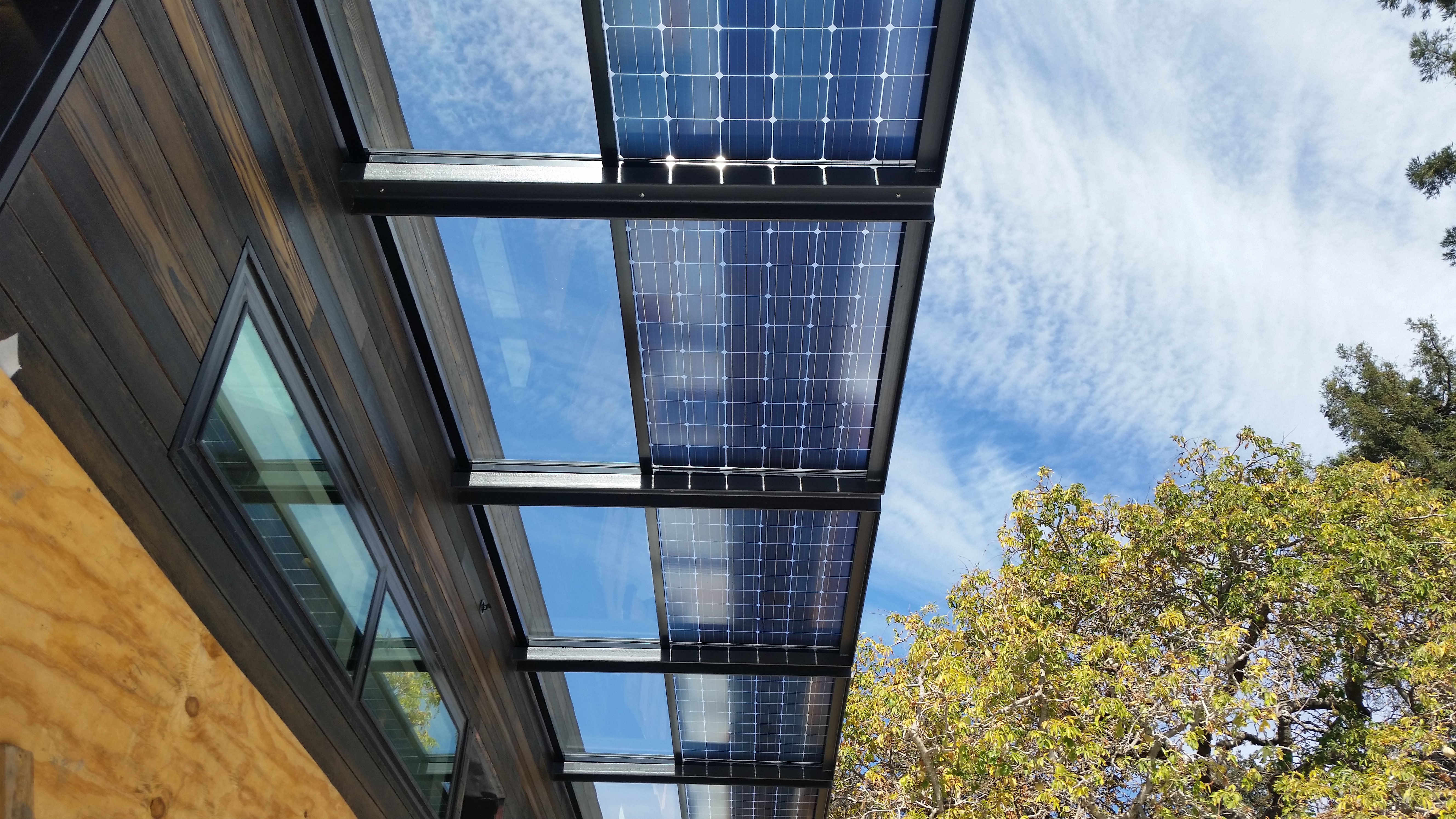
Holding a bifacial module, the most obvious feature is that it is translucent.
· Dual Glass Structure:
Currently, mainstream bifacial modules mostly use "Dual Glass" encapsulation. The front is 2.0mm semi-tempered glass, and the back is also 2.0mm semi-tempered glass (previously, single-sided modules were usually a single piece of 3.2mm glass). This sandwich structure clamps the cells in the middle.
· Frameless vs Framed:
Early on, to prevent frames from blocking light on the back, many bifacial modules were made Frameless. However, because they broke easily during installation, mainstream products still have aluminum alloy frames, but the frames are designed to be narrower, or special treatment is done on the back to prevent shadows from projecting onto the cell edges.
· Junction Box (J-box):
Look at the junction box on the back; it is no longer a large box blocking the middle but is split into three independent small boxes (Split J-box), located at the edges of the module.
The cells inside have changed
You can't just tear off the backsheet and call it a bifacial module; the cell itself must be able to generate electricity on both sides.
· Disappearance of Aluminum Back Surface Field (BSF):
Old-fashioned P-type cells had backs full of aluminum paste (for conduction), which was opaque. Bifacial cells (such as Bifacial PERC, TOPCon, HJT) turn the aluminum layer on the back into thin grid lines (Grid Lines), just like the grid lines on the front.
· Bifaciality Factor:
This is a hard indicator used to measure how much the back resembles the front.
o PERC Cells: Rear efficiency is usually only about 70% of the front. Because the rear grid lines still block a lot of area for conduction.
o TOPCon Cells: Can achieve 80% - 85%.
o HJT (Heterojunction) Cells: Its structure is symmetrical, with the highest bifaciality, reaching 90% - 95%; the back is almost as strong as the front.
The brighter the ground, the better (Albedo)
How much extra electricity a bifacial module can generate is not up to the module factory, but up to the installation environment. This environmental parameter is called Albedo (Ground Reflectivity).
This is the biggest variable when calculating Bifacial Gain. The same 500W bifacial module installed on asphalt versus on snow will have completely different output power levels.
Ground Type | Average Albedo | Expected Generation Gain | Notes |
Asphalt/Dark Soil | 10% - 15% | 4% - 6% | Gain is very low, barely covering the bifacial module premium |
Grass | 20% - 25% | 7% - 10% | Most common ground station scenario |
Concrete/Sand | 30% - 40% | 10% - 15% | Desert PV plants show obvious effects |
White TPO Roof | 70% - 80% | 20% - 25% | Best match for commercial rooftops |
Snow | 80% - 90% | 25% - 30%+ | Note that snow can also block the front |
Installation height and spacing matter
If you buy bifacial modules but install them incorrectly, it's a waste of money. Light reflection requires space.
· Elevation (Height from ground):
If the module is installed sticking to the ground, the back is pitch black and cannot receive any reflected light. Data shows that the lowest point of the module must be at least 1 meter above the ground for the rear gain to be significant. When the height exceeds 1.5 meters, the gain curve tends to flatten.
· Row Spacing (GCR):
There must be gaps between rows to let light hit the ground. If the arrangement is too dense (GCR > 50%), the front row modules will block the light for the ground of the rear row modules. Bifacial module projects usually deliberately increase row spacing; although land is wasted, the output per single module is higher.
· No Rear Shading:
The mounting structure cannot lie across the back of the module. Current trackers or fixed racks use specialized "bifacial designs" to avoid purlins directly crossing the back of the cell cells, otherwise, obvious shadows will occur, which not only reduces generation but also easily creates Hot Spots.
Slow degradation, long life
Besides generating more power, bifacial dual-glass modules have a physical advantage: durability.
· Anti-Micro-cracking:
The cells are sandwiched between two layers of glass, residing in the "zero stress" layer. When the wind blows and the module shakes, the cell cells are not prone to micro-cracks.
· Anti-Water Vapor:
Glass is an inorganic substance and completely impermeable to water. Although traditional plastic backsheets have low water permeability, after 15 or 20 years, water vapor will still penetrate and cause corrosion. Dual-glass modules completely avoid this problem, making them particularly suitable for seaside and floating solar power stations.
· Warranty Data:
Because of this physical characteristic, the linear power warranty for bifacial modules is typically 30 years, while single-sided standard modules are usually 25 years. The annual degradation rate also drops from 0.55% for single-sided to 0.4% or even lower (N-type technology).
Durability & Degradation
Polycrystalline modules typically rely on polymer backsheets, with an average annual linear degradation rate of about 0.6% - 0.7%, and remaining power after 25 years is about 80%.
Bifacial modules mostly use a 2.0mm + 2.0mm dual-glass structure, replacing plastic backsheets with inorganic glass, possessing zero water vapor transmission rates.
Bifacial modules (especially N-type) typically have a first-year degradation lower than 1.0%, a linear annual degradation rate as low as 0.4%, an expected lifespan of over 30 years, and a final power retention rate exceeding 87.4%.
Encapsulation Materials
Front Glass:
Almost all PV modules use low-iron tempered glass as front encapsulation, but they are completely different in thickness and treatment processes.
· Polycrystalline Modules (Single Glass Structure):
o Thickness Standard: Industry standard is typically 3.2mm.
o Process: Fully physically tempered.
o Transmittance: Base transmittance is about 91%, usually coated with an anti-reflective coating (ARC) to boost transmittance to 93% - 94%.
o Weakness: Although 3.2mm glass is strong enough, it only covers one side.
· Bifacial Modules (Dual Glass Structure):
o Thickness Reduction: To control weight, bifacial modules rarely use two pieces of 3.2mm glass (which would make the module weigh over 30kg, making it hard to install). The mainstream solution is to use two layers of 2.0mm or 2.5mm semi-tempered glass.
o Heat Strengthening Treatment: Since 2.0mm glass is too thin, it is difficult to perform traditional full tempering; physical strengthening (Heat Strengthened) processes are usually adopted. Although single-layer strength is slightly lower than 3.2mm fully tempered glass, the combined stiffness formed after laminating two layers of glass with encapsulant is actually higher.
o Photovoltaic Transmittance: The front is consistent with polycrystalline modules, but since the glass is thinner, light absorption by the glass matrix is slightly reduced, theoretically boosting transmittance by a faint 0.5% - 1%.
Encapsulant Materials:
This is a technical detail where the durability gap between polycrystalline and bifacial modules widens, often overlooked by non-professionals. The role of the encapsulant is to bond the cells to the glass/backsheet.
· Polycrystalline Modules (EVA Dominated):
o Material: Ethylene-Vinyl Acetate (EVA).
o Chemical Hazard: EVA is an ester material. In high-temperature and high-humidity environments, EVA easily undergoes hydrolysis reactions, producing Acetic Acid (Vinegar).
o Corrosion Chain: The generated acetic acid is trapped between the glass and backsheet and cannot be released, directly corroding the silver paste grid lines on the cell surface and corroding the TCO (Transparent Conductive Oxide) layer.
· Bifacial Modules (The Rise of POE):
o Material Challenge: The back of a bifacial module is also glass, and the rear cells are very sensitive to PID (Potential Induced Degradation). Ordinary EVA films cannot meet the high water resistance requirements of dual-glass encapsulation.
o Solution: Most high-quality bifacial modules (especially N-type) use POE (Polyolefin Elastomer) or EPE (EVA-POE-EVA) composite films.
o Technical Data:
§ Water Vapor Transmission Rate (WVTR): POE's WVTR is about 2-5 g/m²·day, far lower than EVA's 20-40 g/m²·day.
§ Volume Resistivity: POE's volume resistivity is 1-2 orders of magnitude higher than EVA. In high-voltage systems (like 1500V), leakage current is minimal, greatly reducing the risk of PID effects.
o Acid-Free Characteristic: The POE molecular chain is very stable and will not hydrolyze to produce acidic substances, cutting off the path of cell corrosion from the chemical source.
Rear Protection Layer:
This is the most intuitive feature distinguishing the two types of modules.
· Polycrystalline Modules (Backsheet):
o Structure: Composite multi-layer structure, typically TPT (Tedlar-PET-Tedlar) or KPK (Kynar-PET-Kynar). The middle PET layer provides insulation and mechanical properties, while the outer fluorine-containing material provides weather resistance.
o Physical Thickness: Usually between 0.3mm - 0.4mm.
o Aging Mode:
§ Yellowing: Under long-term UV irradiation, polymers degrade and turn yellow, reducing rear reflectivity and increasing module temperature.
§ Cracking: In thermal cycling caused by day-night temperature differences, due to the different thermal expansion coefficients of plastic and glass, long-term stress accumulation leads to backsheet cracking.
o Breathability: The backsheet is "breathable," allowing trace amounts of water molecules to pass through. While early on this was thought to help expel acetic acid from EVA, it also allows external moisture to enter more easily.
· Bifacial Modules (Rear Glass):
o Symmetry: The rear uses the same 2.0mm glass as the front, with the main difference being that the rear glass is usually drilled (to lead out junction box wires), and some high-end models print a white grid on the inner side of the rear glass to reflect light and increase the utilization of gaps between cells.
o Zero Permeability: Glass is a dense inorganic material with a water vapor transmission rate of 0. This builds a fully enclosed "hermetic capsule."
o Fire Rating: Plastic backsheets can usually only reach Class C fire rating (flammable), while dual-glass structures naturally possess Class A fire rating (non-combustible), which is very favorable for insurance assessments of rooftop PV projects.
Characteristic Indicator | Poly Module Backsheet (Polymer) | Bifacial Module Rear Glass | Impact Result |
Water Vapor Transmission Rate (WVTR) | ~ 1-3 g/m²/day | 0 (Zero) | Bifacial modules are almost immune to moisture corrosion |
Mechanical Hardness | Low (Easily scratched) | High (Mohs hardness 6-7) | Bifacial modules can resist desert sand abrasion |
Thermal Expansion Coefficient | ~ 50 x 10⁻⁶ /K | ~ 9 x 10⁻⁶ /K | Glass matches silicon wafers (3 x 10⁻⁶ /K) better, reducing thermal stress |
UV Blocking | Requires added UV stabilizers | Natural blocking (especially short-wave UV) | Better protection for internal film and cells |
Frames and Sealing:
The last line of defense for encapsulation is the frame and sealant.
· Aluminum Frame: Polycrystalline modules come standard with anodized aluminum frames. Early bifacial modules tried "Frameless" designs to prevent frame shadows from blocking rear generation, using only clamps for installation. However, field data showed that frameless designs caused glass edges to break extremely easily during transport and cleaning. Current mainstream bifacial modules have returned to frame designs, but use half-frames or special profiles with narrower C-sides to minimize rear shading.
· Sealant:
o Polycrystalline modules typically use single-module silicone for edge sealing, mainly for bonding.
o For bifacial dual-glass modules, if a frameless or half-frame design is used, the edges are very sensitive to lateral water vapor infiltration because there is no backsheet wrapping.
Degradation Rate Comparison
Gap at the Starting Line:
From the first few hours to weeks of operation, modules experience a rapid power drop. This is known as "Light Induced Degradation" (LID).
· Polycrystalline Module Performance:
o Boron-Oxygen Complex Defects: Traditional polycrystalline silicon wafers usually use the P-type Boron-doped process. Oxygen atoms are mixed into the silicon ingot during the pulling process. When the module is first exposed to sunlight, boron atoms combine with oxygen atoms to form "Boron-Oxygen complexes" (B-O defects). These complexes capture electrons, reducing minority carrier lifetime.
o Data Quantification: The first-year degradation rate for polycrystalline modules is usually set between 2.0% and 2.5%. A module nominally rated at 300W will have its actual power ceiling permanently dropped to around 292.5W after the first month of operation.
o LeTID Risk: Under the combined action of high temperature (>50°C) and light, polycrystalline modules are also prone to "Light and elevated Temperature Induced Degradation" (LeTID). This is a degradation mechanism that is slower than LID but more destructive; some tests show LeTID can cause an additional 3% - 5% power loss.
· Bifacial Module (Especially N-type) Performance:
o Material Immunity: Modern bifacial modules are mostly based on monocrystalline PERC (using Gallium-doped process) or N-type (TOPCon/HJT) technologies. N-type silicon wafers are doped with Phosphorus, containing absolutely no boron, eliminating the source of B-O complexes at the atomic level.
o Data Quantification: Bifacial PERC modules using gallium-doped wafers can control first-year degradation to 1.5% - 2.0%. N-type bifacial modules are even more aggressive, with first-year degradation usually trending towards 1.0% or even 0.5%.
Long-Run Performance:
After passing the first-year adaptation period, modules enter a linear stable degradation period spanning over 20 years. Tiny percentage differences here, amplified by the compounding of time, translate into huge differences in generation volume.
· Polycrystalline Modules (Backsheet Aging):
o UV Erosion: The polymer backsheet on the back of polycrystalline modules undergoes photochemical degradation under long-term ultraviolet (UV) irradiation. This degradation not only causes the backsheet to yellow (Yellowing), reducing its ability to reflect light from the front gaps, but also increases the water permeability of the encapsulation materials.
o Corrosion Accumulation: As moisture slowly penetrates, the metal grid lines on the cell surface are gradually oxidized, series resistance (Rs) rises year by year, and the fill factor (FF) drops.
o Degradation Rate: Industry standard linear warranties typically allow for 0.55% - 0.7% annual degradation. By year 25, remaining power is typically between 80% - 83%.
· Bifacial Modules (Glass Inertness):
o Inorganic Advantage: Dual-glass encapsulated bifacial modules have glass on both front and back. Glass does not yellow or become permeable over time like plastic. The cells are in a chemically extremely stable environment.
o N-type Stability: N-type cells have lower sensitivity to metal impurities and better control over surface recombination rates.
o Degradation Rate: The average annual degradation rate of bifacial modules is typically promised to be under 0.45%, with some high-end N-type products even promising 0.40%.
o Long-Cycle Calculation: Based on a 0.4% annual degradation rate, bifacial modules can still reach over 87.4% remaining power at the end of year 30. Compared to polycrystalline modules dropping to 80% at year 25, bifacial modules not only run for 5 extra years but also retire in a better state than polycrystalline modules do.
Hidden Dangers of Voltage:
Potential Induced Degradation (PID) is a common performance killer in high-voltage systems (1000V or 1500V).
· Polycrystalline Module Shortcomings:
o In P-type polycrystalline modules, there is a high potential difference between the cell and the grounded aluminum frame. If environmental humidity is high, sodium ions (Na+) will precipitate from the glass, migrate through the EVA film to the cell surface, causing PN junction shunting.
o In IEC 62804 standard tests (85°C, 85% humidity, 96 hours), ordinary polycrystalline modules without specialized anti-PID treatment may suffer a power plunge exceeding 5% - 30%, and this degradation is usually irreversible.
· Bifacial Module Defense Mechanisms:
o Structural Cut-off: Dual-glass modules often use frameless designs or insulated frames, cutting off the leakage current path.
o Film Isolation: The POE film widely used in bifacial modules has a volume resistivity more than 100 times that of EVA, effectively blocking the migration of sodium ions.
o Test Data: Under the same rigorous PID tests, the power degradation of bifacial dual-glass modules is usually negligible (< 1%), demonstrating extremely strong electrical endurance.
Invisible Internal Injuries:
Besides chemical and electrical factors, physical damage caused by mechanical stress is also a major source of degradation.
· Neutral Layer (Neutral Axis) Principle:
o Polycrystalline (Asymmetric): Glass (Hard) + Backsheet (Soft). When the module bends under wind pressure or snow load, the cell cells mainly endure tensile stress (Tension). Silicon wafers are extremely brittle; tension easily leads to micro-cracks.
o Bifacial (Symmetric): 2.0mm Glass + Cell + 2.0mm Glass. This symmetrical structure places the cell cell exactly in the physical "Neutral Layer."
· Impact on Degradation:
Dynamic Mechanical Load (DML) tests by third-party labs like DNV GL (now DNV) show that after 1000 load cycles, Electroluminescence (EL) images of polycrystalline modules usually show multiple black crack areas, with power degradation of 1% - 3%. In contrast, under the same test, bifacial dual-glass modules' EL images often remain intact, with power changes < 0.5%.
Mechanical Strength
"Sandwich" Structure and Neutral Layer Principle
· Polycrystalline Modules (Asymmetric Structure):
o Material Distribution: Front is 3.2mm rigid glass, back is 0.3mm flexible backsheet.
o Stress Performance: When heavy wind or accumulated snow presses on the module surface causing it to bend, due to the inconsistent strength of front and rear materials, the center of force shifts towards the glass side.
o Tensile Effect: At this point, the fragile silicon wafer (only about 160-180 microns thick) sandwiched in the middle is not at the force balance point but endures immense Tensile Stress. Silicon wafers are very brittle; once subjected to tension, they easily develop Micro-cracks invisible to the naked eye.
· Bifacial Modules (Symmetric Structure):
o Material Distribution: Front 2.0mm Glass + Cell + Rear 2.0mm Glass.
o Neutral Layer Protection: This symmetrical "Glass-Cell-Glass" structure creates a perfect I-beam effect in physics. When the module bends, the outer glass is stretched, the inner glass is compressed, but the position right in the middle has zero force.
o Zero Stress: The cell cell sits exactly on this "Neutral Axis." No matter how much wind pressure deforms the module, the cell itself endures almost no tensile force, greatly reducing the risk of micro-cracks.
Static and Dynamic Load Tests
The IEC 61215 standard tests module compression capabilities in two ways: pressing without moving (static) and repeated pushing/pulling (dynamic).
· Static Load (Simulating Snow):
o Standard: The industry universal test standard is 5400 Pa (Pascals), equivalent to bearing 550 kg per square meter.
o Polycrystalline Performance: Relying on 3.2mm thick glass and aluminum frames, polycrystalline modules can usually pass the 5400 Pa test. However, under high loads, the backsheet will undergo obvious physical deformation (bulging or depression).
o Bifacial Performance: Even using thinner 2.0mm glass, the overall bending resistance after dual-layer lamination is superior, with deformation amplitude typically 15% - 20% smaller than polycrystalline modules.
· Dynamic Load (Simulating Gusts):
o Scenario: Strong winds don't press on the module constantly; they blow and pause repeatedly. This cyclic stress most easily leads to metal fatigue and cell breakage.
o DML Test: In Dynamic Mechanical Load tests, modules are subjected to ±1000 Pa pressure, cycled 1000 times.
o Result Comparison:
§ Polycrystalline Modules: Electroluminescence (EL) images after testing often show fine cracks along the main busbars. These cracks may not affect power initially, but will expand with thermal expansion and contraction.
§ Bifacial Modules: Thanks to neutral layer protection, after undergoing the same 1000 cycles, EL images usually remain intact, with power degradation often < 0.5%, which is almost negligible.
Impact Resistance Difference of Glass Types
Although bifacial module glass is thinner, it doesn't mean it's more brittle. This involves changes in glass treatment processes.
· Polycrystalline Modules (Fully Tempered Glass):
o Use 3.2mm Fully Tempered glass.
o Advantage is extremely high hardness; once broken, it shatters into obtuse small granules, meeting safety glass standards.
o The disadvantage is that if the glass contains trace nickel sulfide impurities, there is a very low probability risk of Spontaneous Breakage.
· Bifacial Modules (Semi-Tempered/Heat Strengthened Glass):
o Use 2.0mm Heat Strengthened glass.
o Because 2.0mm is too thin, full tempering cannot be performed (otherwise it warps easily). The surface stress of heat-strengthened glass is lower than fully tempered, but flatness is better.
o Impact Resistance: Although single-sheet strength is inferior to 3.2mm fully tempered, two sheets bonded by encapsulant form a structure similar to a car windshield. In IEC standard Hail Tests (25mm diameter ice ball hitting at 23 m/s speed), the breakage rate of dual-glass modules is extremely low.
o Advantage: Heat-strengthened glass has almost no spontaneous breakage risk, solving a maintenance pain point for large power stations.
Hidden Damage During Transport and Installation
The greatest mechanical damage to modules often happens not during power station operation, but during truck transport and worker handling.
· Torsional Rigidity:
o When handled on uneven ground, modules are prone to diagonal twisting.
o Polycrystalline modules have poor twist resistance because the backsheet is soft. Once twisted, the cell cells shatter easily.
o Bifacial dual-glass modules are like a hard brick, with extremely strong twist resistance. Under rough construction conditions (e.g., rough handling by workers), the probability of internal damage to bifacial modules is lower.
o Frameless Design Trap and Return:
§ Early bifacial modules tried Frameless designs to pursue dual-side light reception.
§ Field data showed that the glass edges of frameless modules were very fragile; slight bumps during installation would cause the entire glass to shatter.
§ Status Quo: Current mainstream bifacial modules have returned to Framed designs (usually anodized aluminum). This design protects glass edges while using silicone or butyl rubber inside the frame groove to provide extra cushioning, further enhancing overall mechanical strength.
Ground reflectivity
Polycrystalline module backsheets are usually opaque Tedlar or EVA materials, having zero response to ground reflected light.
In contrast, bifacial modules receive reflected radiation via rear cells, and their Bifacial Gain is positively linearly related to ground albedo.
Outside of Standard Test Conditions (STC), grass environments (albedo ~20%) usually bring 7% - 10% extra generation to bifacial modules;
Whereas in white TPO roof or snowy environments (albedo >60%), gains can break through 25%.
If installation height is lower than 0.5 meters, the module's own shadow will block the reflection path, causing the actual performance of bifacial modules to fall back to the level of polycrystalline modules, thus losing the economic basis for the premium.
Differences in Light Energy Utilization
Does the back block or transmit light?
· Polycrystalline Modules:
The back is usually encapsulated with a layer of white or black Tedlar (PVF) or PET composite backsheet. This material is opaque. When ambient light (diffuse reflection or ground reflection) hits the back of a polycrystalline module, photons are absorbed by the backsheet material and converted into Phonons (Heat Energy), causing the module temperature to rise, which conversely lowers the output voltage of the front cells. Light energy utilization here is a negative value.
· Bifacial Modules:
The back uses photovoltaic glass (usually 2.0mm thick) or a transparent organic backsheet. Light penetrates the glass directly to the passivation layer on the back of the cell. The indicator measuring this capability is Bifaciality.
o p-PERC Bifacial Modules: Due to large shading by rear aluminum grid lines, bifaciality is usually 70% ± 5%. Meaning if the front generates 100W, the back can generate 70W under the same illumination.
o n-TOPCon or HJT Bifacial Modules: Rear grid lines are thinner, and the wafer structure is symmetrical, so bifaciality can be boosted to 80% - 85%.
Crystal Structure Trapping Electrons
After photons enter the cell and excite electrons, the microstructure of polycrystalline vs. bifacial (usually based on monocrystalline technology) determines whether electrons can smoothly escape to become current.
· Grain Boundary Recombination in Polycrystalline:
Polycrystalline silicon is composed of many small grains with different orientations. The interface between grains is called the Grain Boundary. Grain boundaries contain large amounts of dangling bonds and impurities, forming deep-level recombination centers.
o Data Performance: When photons excite electron-hole pairs far from the PN junction, the minority carrier lifetime in polycrystalline silicon is typically only 1-5 microseconds.
o Result: This causes a significant drop in Internal Quantum Efficiency (IQE) for polycrystalline modules in the long-wave band (red light and near-infrared), locking overall conversion efficiency at 18% - 19%.
o Monocrystalline Bifacial's Unimpeded Channel:
Bifacial modules generally use monocrystalline silicon wafers, with neat atomic arrangement and no grain boundary interference.
§ Data Performance: Monocrystalline silicon minority carrier lifetime is usually over 100 - 1,000 microseconds, two orders of magnitude higher than polycrystalline.
§ Result: Even for infrared photons with long penetration depths (wavelength > 900 nm), electrons excited deep in the wafer have enough time to diffuse to the PN junction and be collected. This sets the baseline conversion efficiency of bifacial modules starting above 21.5%.
Scattered Light on Cloudy Days and Morning/Evening
Sunlight doesn't always shoot straight down. In the early morning, evening, or cloudy weather, Diffuse Horizontal Irradiance (DHI) dominates.
· Rayleigh Scattering Effect:
Shorter wavelength blue-violet light is more easily scattered by atmospheric molecules. On cloudy days, Direct Normal Irradiance (DNI) is close to zero, and the ground receives almost entirely scattered light. Scattered light is "omnidirectional," meaning light shoots at the module from all directions.
· Reception Capability Comparison:
o Polycrystalline Modules: Can only capture scattered light falling on the front. Since their surface usually uses worm-like structures formed by Acid Texturing, their ability to capture high-angle scattered light is weaker than the pyramid structure of monocrystalline.
o Bifacial Modules: Scattered light shines not only on the front but also on the back. On cloudy days, the sky itself is a huge scattered light source, plus ground diffuse reflection, the irradiance on the back is not much lower than the front.
o Measured Data: In fully cloudy environments, the total generation of bifacial modules is usually 5% - 8% higher than polycrystalline modules of the same wattage.
Refraction Loss of Oblique Light
The sun moves constantly throughout the day, and the time light hits the module vertically is very short. Most of the time, light enters obliquely. This involves the Incidence Angle Modifier (IAM).
· Glass-Air Interface:
When light enters glass from air, reflection occurs.
o Polycrystalline Modules (Single Glass): Only one layer of glass. After light passes through glass and hits the EVA film and cell, if unabsorbed photons reflect back to the glass-air interface, most will escape.
o Bifacial Modules (Dual Glass): Although there is an extra layer of glass, the internal reflection path is more complex. Part of the light passing through cell gaps, or light reflected by the cell surface, will undergo Total Internal Reflection between the two layers of glass, increasing the probability of photons striking the cell surface again.
· Morning/Evening Differences:
When the solar incident angle is greater than 60 degrees (before 8 AM or after 4 PM), reflection losses for ordinary polycrystalline modules increase sharply. High-quality bifacial modules, usually combined with anti-reflective coatings (ARC) and aided by the Light Trapping effect of the dual-glass structure, can retain more oblique light energy. This extends the effective generation time of bifacial modules by about 10-15 minutes in the morning and evening each.
Ground Surface Material
Black Asphalt Road
· Physical Characteristics: Newly laid asphalt consists of dark black tar and aggregate, having a very high light absorption rate. Photons hitting the surface are almost entirely swallowed and converted to heat.
· Data Performance:
o New Asphalt: Albedo is extremely low, usually 4% - 5%.
o Aged Asphalt: After oxidation and dust accumulation, color turns dark gray, albedo rises to 10% - 12%.
· Module Comparison:
o Polycrystalline Modules: Thermal radiation (long-wave infrared) from the hot ground will actually heat the module, causing voltage drop.
o Bifacial Modules: On new asphalt, the rear contribution is almost zero. Considering dual-glass modules usually cost 0.5 - 1 cent more per watt than polycrystalline, the 1% - 2% generation gain here cannot cover the extra BOM cost.
Soil and Sand
· Physical Characteristics: Different soil mineral compositions determine the color and intensity of reflected light. Iron-rich red soil has lower reflectivity, while quartz-containing sandy soil has higher reflectivity.
· Data Performance:
o Dark Humus Soil: Albedo 15% - 20%.
o Dry Sand/Desert: Albedo 25% - 30%.
o Light Clay: Albedo 20% - 35%.
· Spectral Response Difference:
Sand reflects the near-infrared band (700nm - 1100nm) stronger than the visible band. Silicon-based batteries (whether poly or mono) happen to be very sensitive to this band.
· Module Comparison:
In desert environments, bifacial modules can achieve stable gains of 8% - 12%. Although polycrystalline modules can work in deserts, bifacial modules use rear photocurrent to offset power degradation caused by high temperatures.
Green Grass and Crops
In "Agrivoltaics" projects, plants are the main background.
· Physical Characteristics: Plant chlorophyll absorbs red and blue light for photosynthesis but strongly reflects green light and near-infrared light (NIR). This is called the "Red Edge" effect.
· Data Performance:
o Ordinary Grass: Average albedo 15% - 25%.
o Dry/Withered Grass: Albedo can rise to over 30%.
· Dynamic Changes:
Grass height is a variable. If grass grows too high (over 0.5 meters), it not only blocks rear light entry but also hinders air circulation behind the module, raising working temperatures.
· Module Comparison:
Polycrystalline modules have a mediocre response to green light reflected by grass. Bifacial modules (especially n-type TOPCon) have stronger capture capabilities for near-infrared light reflected by plants. Field data shows that on neatly trimmed grass, bifacial gain maintains around 6% - 8%.
Concrete and Gravel
Standard configuration for commercial rooftops and substation grounds.
· Physical Characteristics: Concrete surfaces are rough, producing ideal Diffuse Reflection, distributing light evenly, which helps reduce current mismatch between cells.
· Data Performance:
o New Concrete: Light color, albedo 30% - 35%.
o Old Concrete: Darkens, albedo drops to 20% - 25%.
o White Gravel: Artificially laid reflection layer, albedo can reach 40% - 50%.
· Economic Calculation:
On flat concrete roofs, bifacial modules typically bring 10% - 15% generation increase.
White Roof Membrane
This is the "multiplier" for bifacial module performance, common on large warehouse roofs in Europe and America.
· Material Types: Thermoplastic Polyolefin (TPO), PVC, or Acrylic Cool Roof Coatings.
· Data Performance:
o Brand New White TPO: Albedo as high as 75% - 85%.
o After Three Years: Due to oxidation and dust, stabilizes at 55% - 60%.
· Extreme Value Effect:
In the first few months after installation, high reflectivity leads to a surge in bifacial module current, potentially even hitting the inverter's "DC Clipping" point.
· Module Comparison:
Polycrystalline modules on this roof not only cannot use reflected light but also, because the white roof reflects a lot of thermal radiation, ambient temperature is slightly lower than black roofs, though the efficiency boost is minimal. In contrast, bifacial modules here can achieve amazing gains of 20% - 30%, with LCOE (Levelized Cost of Electricity) far lower than polycrystalline modules.
Winter Snow
· Physical Characteristics: Ice crystal structures almost totally reflect visible light.
· Data Performance:
o Fresh Dry Snow: Albedo 80% - 90%.
o Melting Wet Snow: Albedo 40% - 60%.
· Snow Melting Mechanism Difference:
o Polycrystalline Modules: Once the front is covered by snow, generation stops. Relies only on gravity or manual removal.
o Bifacial Modules: As long as the back is exposed to scattered light or side reflected light, the cell works and generates heat. This heat conducts to the front glass, forming a water film between the glass and snow, prompting the snow to slide off.
Installation Height
Shadows too dark to use
The closer the module is to the ground, the deeper the shadow it casts directly underneath. This involves a geometric optics concept: Umbra and Penumbra.
· Ground-Hugging Installation (< 0.3 meters):
At this point, the ground behind the module is completely in the "Umbra" zone. Sunlight is thoroughly blocked by the module, and the illuminance directly below is close to zero.
o Bifacial Module Performance: Since the view from the back is pitch black, received reflected radiation is extremely low. At this point, bifacial module performance is almost indistinguishable from polycrystalline modules, or may even be slightly lower due to poorer ventilation caused by dual-glass frames blocking airflow.
o Polycrystalline Module Performance: Works normally. As long as there is light on the front, it doesn't care if it's dark underneath.
· Elevated Installation (> 0.8 meters):
As height increases, surrounding Diffuse Light can creep under the module, and the originally pitch-black shadow fades, forming a "Penumbra" zone.
o Bifacial Module Performance: Ground brightness increases, and light intensity reflected back increases. Data shows that raising height from 0.2 meters to 1.0 meter typically increases effective rear irradiance by 3 to 4 times.
o Unevenness Risk: Low height leads not only to less light but also to uneven lighting (dark in the middle, bright at edges). This unevenness triggers Mismatch Loss within cell strings, further dragging down output power.
How wide is the field of view
Engineers usually use the View Factor to quantify how much ground the back of the module can "see." This value is between 0 and 1.
Geometric Relationship:
The View Factor is determined by the ratio of module width (chord length) to height from the ground:
l When tight to the ground: View factor is almost zero.
l At infinite height: View factor is about 0.5 (for an infinite plane).
Data Saturation Point: Gain does not grow linearly with height indefinitely.
n 0.2m to 0.5m: Every 10cm lift may boost bifacial gain by 1% - 1.5%.
n 0.5m to 1.0m: Growth slows. Every 10cm lift boosts gain by about 0.5%.
n Over 1.2m: Curve enters a plateau. The optical return from continuing to raise the rack is very low, with significant diminishing marginal utility.
For polycrystalline modules, this complex geometric parameter is completely invalid; its output power is always a straight line regardless of how the view factor changes.
How much does it cost to raise
To raise modules for optical gain, physical costs must be paid. This involves moment (Torque) calculations in structural engineering.
· Wind Load Amplification:
The higher the module installation, the greater the wind speed typically encountered (wind shear effect), and the longer the lever arm of wind force acting on the foundation.
o Moment Formula: M = F × L. If height is increased from 0.5m to 1.5m, under the same wind pressure, the bending moment at the root increases by 2 times.
o Steel Usage: To resist this larger bending moment, racking piles need thicker sections or deeper driving depths. Typically, raising ground clearance from 0.6m to 1.2m leads to a 10% - 15% increase in racking steel weight.
· Cost Critical Line:
o Polycrystalline Systems: No need to dwell on this. To save money and facilitate construction, the design principle is usually "as low as possible without being buried by snow or flooded," typically 0.3 - 0.5 meters off the ground.
o Bifacial Systems: A balance point must be found. 0.8 meters - 1.0 meters is generally considered the economic "sweet spot."
Too close to the ground causes fever
Besides light, air circulation is also a physical quantity affecting efficiency. This involves Operating Temperature.
· Heat Pocket Effect:
When modules are installed close to the ground, module heat generation heats the air below. If the air cannot flow away smoothly, a hot air pocket forms, continuously baking the back of the module.
o Polycrystalline Modules: Temperature coefficient is usually -0.38%/°C to -0.41%/°C. If hugging the ground causes a 5-degree temp rise, power is lost by 2%.
o Bifacial Modules: Although the dual-glass structure has higher heat capacity, if too close to the ground (< 0.2m), the back gets no light and suffers from poor heat dissipation due to airflow blockage.
· Height and Cooling:
Raising modules favors the Venturi Effect or simple natural convection.
o Data Measurement: At noon in summer, the operating temperature of modules 1.0m off the ground is usually 3 - 5 °C lower than modules 0.2m off the ground.
o Double Bonus: For bifacial modules, raising the height increases light (numerator) and decreases temperature rise (denominator), obtaining a double positive correction in the power output formula.
Weeding maintenance trouble
Height also directly affects the complexity and cost of later Operations & Maintenance (O&M).
· Vegetation Shading:
If the project is on grass, weeds grow amazingly fast.
o Below 0.5m: Weeds easily grow past the lower edge of the module. For polycrystalline modules, this leads to severe Hot Spot Effects, potentially burning out diodes.
o Bifacial Specifics: Even if weeds don't block the front, as long as they grow high enough, they block the ground reflection path, forcibly downgrading "bifacial modules" to "single-sided modules."
· O&M Frequency:
o Low Installation (Common for Poly): May require weeding 3-4 times a year.
o High Installation (Recommended for Bifacial): Over 1.2m off the ground allows weeds to grow naturally to a certain height without affecting rear light entry, or allows mechanical mowers to drive directly in for work, significantly reducing manual labor hours for O&M.