Why Bifacial Solar Panels are More Efficient | 3 Reasons
Bifacial solar panels significantly outperform traditional monofacial modules by utilizing a dual-sided design that captures reflected sunlight from the ground, known as the albedo effect, which typically increases total energy generation by 5% to 30% depending on surface reflectivity like snow or white rooftops.
Unlike standard panels with opaque backsheets that waste reflected photons, bifacial modules feature a transparent rear side that actively converts scattered light during early mornings, late afternoons, and cloudy days, effectively extending the daily high-power production window by approximately 30 to 45 minutes.
Furthermore, their robust double-glass structure provides superior mechanical protection against environmental stress, lowering the annual degradation rate to just 0.4% compared to 0.55% for conventional panels, resulting in a guaranteed power output of over 87.4% after 30 years of continuous operation.
Albedo Effect
Albedo Calculation
In PVsyst or SAM simulation software, small deviations in input values can lead to 3% to 5% errors in power generation simulation results.
Typically, fresh dry snow is the king of reflection, with Albedo values as high as 0.80 to 0.95, meaning for every 1,000 W of incident light per square meter, 800 W to 950 W will be reflected. The instantaneous power gain of bifacial modules in such scenarios can soar to 25% or even 30%.
In contrast, old asphalt roofs are almost like blackbodies, with Albedo only 0.05 to 0.10, reflecting almost no light. In this case, the backside gain of bifacial modules will plummet to below 3%, making them almost no different from monofacial modules.
If installed on ordinary grass, the reflectivity fluctuates around 0.15 to 0.25, depending on the yellowness and density of the grass;
On flat concrete ground, this value stabilizes between 0.25 and 0.35. For a 50 MW power station, if the site is selected on light-colored sand (Albedo ≈ 0.35) compared to dark soil (Albedo ≈ 0.15), the first-year power generation can increase by 3.5 million to 4.5 million kWh.
Most Cost-Effective Paving
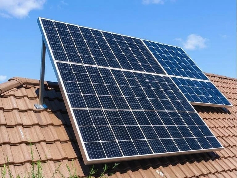
In commercial rooftop projects, using white TPO (Thermoplastic Polyolefin) waterproofing membranes or applying high-reflectivity white paint can force the roof albedo up to 0.70 to 0.80.
Measured data shows that in regions at 35 degrees north latitude, increasing the roof reflectivity from 0.20 to 0.75 will increase the total annual power generation of the system by 12% to 15%.
If your project uses 580W bifacial modules, this modification can make the actual average daily output of a single module equivalent to a 650W giant module.
Although the cost of laying white geotextiles or paint is approximately $3 to $5 per square meter, considering the additional 0.15 to 0.20 kWh produced per watt each year, this modification cost can usually be recovered through extra electricity revenue within 2.5 to 3.5 years.
It should be noted that these high-reflectivity materials require maintenance. Dust coverage can cause the reflectivity to decay from 0.80 to 0.60 within six months, so the O&M budget must include the cost of high-pressure water gun cleaning once per quarter, with each cleaning costing about 0.5% of the power station's annual income.
Higher Elevation for Light Absorption
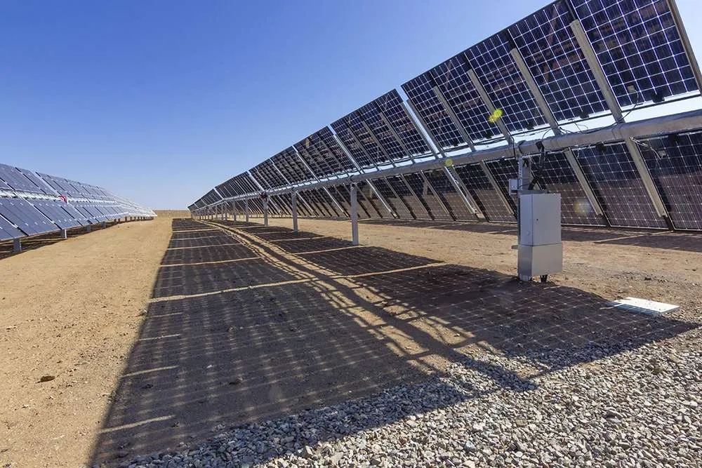
If the lowest point of the module is only 0.2 meters from the ground, the backside field of view is restricted, the self-shading is most intense, and the backside irradiance uniformity is extremely poor, which may lead to local hot spots and severe mismatch losses.
Data indicates that increasing the ground clearance from 0.2 meters to 0.5 meters results in an exponential growth in backside radiation received, with the gain jumping from 2% to 8%.
Continuing to increase from 0.5 meters to 1.0 meter makes the gain curve start to flatten, usually adding another 3% to 5% of power generation;
Exceeding 1.5 meters enters a saturation zone, where every 0.5 meter increase only brings about 0.5% in generation gain, but this will increase the cost of steel brackets by 10% to 15%, and the wind resistance requirements will also increase accordingly.
Therefore, 1.0 meter to 1.2 meters is generally considered the "golden height" for ground power stations.
At this height, the backside irradiance inhomogeneity can be controlled within 10%, maximizing the reduction of power loss caused by diode conduction triggered by local shading.
Avoid Over-Dense Arrangement
If you set the GCR to 0.6 or 0.7 (i.e., the projected area of modules accounts for 60%-70% of the land area), the shadows of front-row modules will heavily block the ground below the rear-row modules during morning and afternoon periods, reducing effective reflected light by more than 40%.
The optimal GCR range for bifacial modules is usually between 0.35 and 0.45, meaning a passage equivalent to 1.5 to 2 times the module width must be left between each row of modules.
In a 100-mu site, although reducing the GCR means the total installed capacity drops from 6MW to 4.5MW, the energy yield per watt (kWh/kWp) will increase by 8% to 12%, and the system's Levelized Cost of Energy (LCOE) will actually be lower.
Especially in desert or wasteland projects where land rent is low, increasing the spacing to lower the GCR to 0.3, combined with a ground reflectivity of 0.4, can easily push the bifacial gain past 15%.
Inverter Configuration
For monofacial modules, to spread out inverter costs, they are usually oversized at a ratio of 1.25 to 1.30 (i.e., 1.3 MW of modules for a 1 MW inverter).
However, in bifacial module systems, if the ground reflectivity exceeds 0.5 (such as snow or white roofs), the backside gain may reach 20%. At this time, the actual output power on the module side often exceeds 1.1 times the nominal value.
If you still use a 1.3 ratio to configure the inverter, during the high-light periods from 11:00 to 14:00, the inverter will frequently trigger clipping, wasting excess electricity.
Data shows that in high-reflectivity scenarios, the DC/AC ratio for bifacial modules is recommended to be controlled between 1.10 and 1.15.
For projects using tracking brackets and with Albedo > 0.4, a 1.05 ratio is even recommended.
Although the initial inverter investment increases by $0.01 per watt, the saved clipping losses can be worth tens of thousands of dollars annually, avoiding the waste of revenue caused by "a small horse pulling a large cart."
Bracket Shading Prevention
If traditional purlins pass horizontally across the back of the module, they will directly block 3% to 5% of the cell area.
Since photovoltaic cells are connected in series, this 5% physical shading can cause the entire string's output current to drop by 10% or even more.
Bracket systems specially designed for bifacial modules must minimize backside beams or keep them at least 50 mm away from the module backsheet to allow scattered light to wrap into the shadow area.
Current mainstream 1P (single row vertical) or 2P (double row vertical) tracking brackets design the main axis as a hexagonal or octagonal tube, strictly control the axis width between 100 mm and 150 mm, and use special clamps to elevate the modules.
Tests show that brackets with a backside shadow-free design can recover an additional 2.5% to 4% of bifacial gain compared to traditional brackets.
When purchasing brackets, the "backside shading rate" parameter must be reviewed, requiring it to be below 1.5%; otherwise, half of the performance of the high-priced bifacial modules you bought will be consumed by the bracket.
Bifacial Design
Bifaciality Ratio Gap
Traditional P-type PERC cells, originally designed with a full-coverage aluminum back surface field for conduction, were modified to have local aluminum grid lines for bifaciality.
This results in a large shaded area on the back, with the bifaciality ratio usually stuck in the 70% ± 5% range.
This means if the front side can generate 550 W, the back side can only generate 385 W at most, even under identical light conditions. In contrast, current mainstream N-type TOPCon cells, with their naturally symmetrical passivated contact structure, have a bifaciality ratio that jumps directly to 80% to 85%.
This generational gap means that under the same ground reflection conditions, the actual per-watt yield of N-type modules is 3.5% to 5% higher than that of P-type.
Even more extreme are Heterojunction (HJT) cells, whose bifacial structure is almost completely symmetrical, allowing the bifaciality ratio to soar to 90% or even 95%.
In vertical installation or high-latitude snow scenarios, the HJT backside generation capability is almost equal to the front.
This structural transparency directly determines the baseline LCOE for the 25-year life cycle of the power station.
"Under a typical backside reflected irradiance of 130 W/m², every 10% increase in bifaciality ratio increases the module's integrated output power by 1.5% to 1.8%. For a 100MW project, this 10% bifaciality gap is equivalent to 2 million kWh of free electricity every year."
Double the Glass Thickness
To allow light to reach the back, opaque TPT/KPE polymer backsheets were removed and replaced with a "Double-Glass" structure.
This design typically uses two pieces of 2.0 mm thick semi-tempered glass to sandwich the solar cells like a sandwich.
Don't underestimate this change from 3.2mm single-layer glass to 2.0mm + 2.0mm double-layer glass; it causes the weight of 72-cell large-format modules to jump from 22 kg to 32 kg or even 35 kg.
This 10 kg+ weight increase is a huge physical challenge for installers and also requires the bracket system's load-bearing redundancy to increase by more than 15%.
However, the physical gain brought by this back glass is significant: it achieves zero water permeability.
Traditional backsheets have a water vapor transmission rate of about 1-3 g/m²/day, which can lead to cell edge corrosion or snail trails over long-term operation.
Glass, being inorganic, completely seals out moisture, reducing the annual degradation rate of bifacial modules in high-temperature and high-humidity environments from 0.55% to 0.40%.
Additionally, although 2.0 mm glass is thin, after heat treatment and when combined with the frame, it can withstand a front snow load of 5400 Pa and a back wind load of 2400 Pa. Its micro-crack resistance is more than 30% higher than that of monofacial modules.
Separated Junction Box Installation
Early monofacial modules had a large rectangular junction box fixed right in the center of the module's back, blocking the most core strings of cells. To solve this, bifacial modules have widely adopted a "Split J-Box" design.
Engineers split the originally centralized large box into three independent small boxes, placing them at the edges or top center of the module.
Each small box houses a bypass diode, usually with a rated current between 25A and 30A, to handle the high current impact from bifacial light reception.
This layout frees up more than 98% of the backside surface area to receive reflected light, not only reducing physical shading but also optimizing heat dissipation paths.
Three dispersed small heat sources are 20% more efficient at dissipating heat than one centralized large source, reducing the internal operating temperature of the junction box by 5°C to 10°C.
At the same time, this design, paired with 4mm² cross-section cables of 300mm or 1,200mm length, allows for "leap-frog" or horizontal connections in the array, reducing DC cable usage by about 10%.
Choosing the Right Encapsulant Film
In monofacial modules, inexpensive EVA (Ethylene-Vinyl Acetate) film is the standard.
However, in bifacial modules, there is no "breathing" channel between the back and front glass. Acetic acid produced by EVA decomposition cannot escape and will corrode the cell grid lines.
Therefore, bifacial modules typically require the use of POE (Polyolefin Elastomer) or EPE (EVA-POE-EVA co-extruded) films.
The volume resistivity of POE is two orders of magnitude higher than EVA, and its water vapor barrier rate is more than 10 times higher.
Most importantly, it can completely eliminate Potential Induced Degradation (PID).
In 1500 V high-voltage DC systems, without the protection of POE film, sodium ions will migrate to the cell surface under the electric field, causing module power to plummet by 5% to 30% within a year.
Although POE film costs 15% to 20% more per square meter than EVA, this layer of "invisible body armor" is the chemical defense line that ensures bifacial modules maintain a power retention rate above 87.4% during their 30-year warranty period.
Do Frames Block Light?
While standard 30mm or 35mm anodized aluminum frames provide rigidity, they cast shadows 5mm to 15mm wide on the edge cells of the back side when the sun is at an oblique angle.
This is critical for series circuits, as the "bottleneck effect" will pull down the output of the entire string.
To mitigate this, modern high-efficiency bifacial modules use a "Half-height C-side" design, shortening the length of the frame's C-side on the back, or directly adopting a frameless double-glass clamp solution.
Although the frameless design completely eliminates edge shadows and allows snow and dust to slide off more easily (self-cleaning effect), it also leaves the glass edges directly exposed to the risk of bumping during transport and installation, with breakage rates rising from 0.1% to about 1%.
Consequently, the current mainstream solution is still to retain the frame but apply high-reflectivity white paint on the back or compress the back frame height to the limit, attempting to recover that 0.5% to 1% edge shading loss.
"At an installation height of 1.5 meters, traditional 35mm frames cause approximately 1.2% irradiance loss on the back of the module annually. By optimizing the frame cross-section design and using transparent sealant, this loss can be compressed to within 0.3%."
Round Ribbons are Better
Traditional flat ribbons directly reflect part of the incident light back to the glass and then out, causing about 2% to 3% shading loss.
Bifacial modules now commonly use Round Wire or triangular ribbons, paired with SMBB (Super Multi-Busbar) technology, usually 16 or 20 busbars.
The diameter of the round ribbon is only 0.25 mm to 0.35 mm. It can perform a secondary reflection of the light hitting the ribbon, bouncing it obliquely onto the cell surface to be absorbed, which is known as the "zero shading" or "light trap" effect.
For bifacial modules, round ribbons work equally well on the back, effectively capturing wide-angle scattered light from the ground.
Data shows that compared to traditional 5-busbar flat ribbons, bifacial modules using SMBB round ribbons see an optical utilization increase of 1.5% to 2.0%.
Moreover, due to the dense solder joints, there are more current transmission paths after a busbar break, and the ability to resist micro-crack risks is correspondingly enhanced.
Diffuse Light Conditions
Capturing More Light at Morning and Evening
During the early morning from 6:00 to 8:00 and late evening from 17:00 to 19:00, the sun moves along the horizon, with altitude angles usually below 20 degrees.
At these times, the path length of sunlight through the atmosphere (Air Mass) reaches AM5.0 or even higher, which is more than 3 times the AM1.5 path at noon.
A long path means that most high-energy direct light is scattered by gas molecules and suspended particles in the atmosphere, forming what is known as "Rayleigh Scattering."
During these periods, the direct module (Beam Module) received by the ground may drop below 300 W/m², while the diffuse module (Diffuse Module) ratio can soar to 50% or even 70%.
In the morning and evening, the space between heaven and earth is filled with diffuse light from all directions. The bifacial light-receiving structure of the bifacial module allows it to maintain operating voltage even during this "off-peak time."
Measured data shows that within 1.5 hours after sunrise and before sunset, the output power of bifacial modules is typically 15% to 20% higher than monofacial modules of the same specification.
If the inverter's startup voltage is set to 200V, bifacial modules often "wake up" 30 minutes earlier and "go to sleep" 30 minutes later than monofacial modules. This extra one hour of low-light generation per day adds up to 365 hours of extra operating time per year.
No Slumping on Cloudy Days
When cloud thickness reaches a certain level, such as when stratocumulus coverage exceeds 80%, Direct Normal Irradiance (DNI) is abruptly blocked, and ground irradiance can instantly drop from 900 W/m² to below 200 W/m².
At this point, all light consists of "Mie Scattering" light after multiple reflections through water droplets in the clouds, which is non-directional and uniformly distributed in all directions.
This kind of light is a nightmare for traditional modules that rely on specific direct angles, with output current dropping to single-digit Amperes.
Bifacial modules show extreme resilience in such scenarios. Because diffuse light is not picky about angles, it uniformly envelops both the front and back of the module.
For N-type modules with an 80% bifaciality ratio, the backside cells are just as efficient as the front at this time, greedily absorbing weak light from the ground, cloud reflections, and even reflections from surrounding buildings.
Data indicates that under overcast conditions, the relative gain of bifacial modules is actually higher than on sunny days, reaching 10% to 15%.
Weather/Irradiance Scenario | Direct Irradiance Ratio (DNI) | Diffuse Irradiance Ratio (DHI) | Monofacial Module Output Efficiency (Baseline) | Bifacial Module Output Efficiency (Comparison) | Relative Gain (Gain) |
Sunny Noon | > 85% | < 15% | 100% | 108% - 110% | 8% - 10% |
Partly Cloudy | 40% - 60% | 40% - 60% | 55% | 62% - 65% | 12% - 18% |
Heavy Haze/Rainy | < 10% | > 90% | 15% | 17.5% - 19% | 16% - 25% |
Morning/Evening | < 30% | > 70% | 25% | 30% - 32% | 20% - 28% |
Large Backside Aperture
The ability of bifacial modules to utilize diffuse light is also related to their spectral response characteristics.
In diffuse light, short-wavelength blue-violet light has a higher proportion (because shorter wavelengths are easily scattered), while long-wavelength red light penetrates more easily.
Crystalline silicon cells themselves are very sensitive to the near-infrared band (700 nm - 1100 nm) but respond to the average-ly to short-wave bands.
However, the back glass of bifacial modules usually uses high-transmittance white glass. Compared to the front glass treated with anti-reflective coating, the back can be quite efficient at capturing blue light coming in at specific diffuse angles.
More crucial is the "View Factor." In an environment full of diffuse light, light is not a straight line but more like a mist. The back of a monofacial module is a closed aluminum backsheet, equivalent to sealing off half of the light-sensing area.
The bifacial module is transparent front and back, and its effective light-sensing aperture is 1.8 times that of a monofacial module (considering bifaciality loss).
In environments dominated by diffuse light, light will seep into the gaps of the bracket and reach the back of the module. Especially when the module tilt angle is large (such as above 30 degrees), the back actually faces a large portion of the sky's diffuse radiation.
In high-latitude regions like Northern Europe, where most of the long winter daylight consists of low-angle diffuse light, the back of a bifacial module can contribute more than 30% of the total power generation.
Working Even When Standing Vertically
In some agrivoltaic or noise barrier projects, bifacial modules are installed vertically (90 degrees) to the ground, usually facing East-West.
In this extreme posture, direct light at noon is not only scarce but also comes at a poor angle (skimming across the panel), which might seem like it would not generate power or even lose money.
But look at the morning and evening data: in the morning, the front faces the rising eastern sun; in the afternoon, the back faces the setting western sun. And at noon, although direct light utilization is low, the vertical panel has an extremely strong ability to capture diffuse light from the sky overhead and the ground.
In regions above 45 degrees latitude, vertically installed bifacial modules can generate 10% to 20% more power in winter than traditional south-facing tilted installations.
The reason is simple: the winter sun is low, diffuse light is strong, and vertical surfaces do not accumulate snow. The high reflectivity of snow (Albedo > 0.8), combined with ubiquitous diffuse light, allows both sides of the vertical module to work at full load.
For areas with expensive land, this installation method can reduce land occupancy by more than 90% while ensuring that the power output per mu does not decrease but increases, relying on the bifacial module's all-round ability to absorb diffuse light.