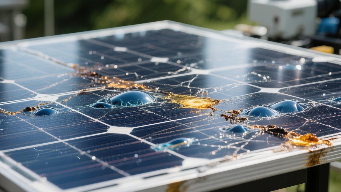
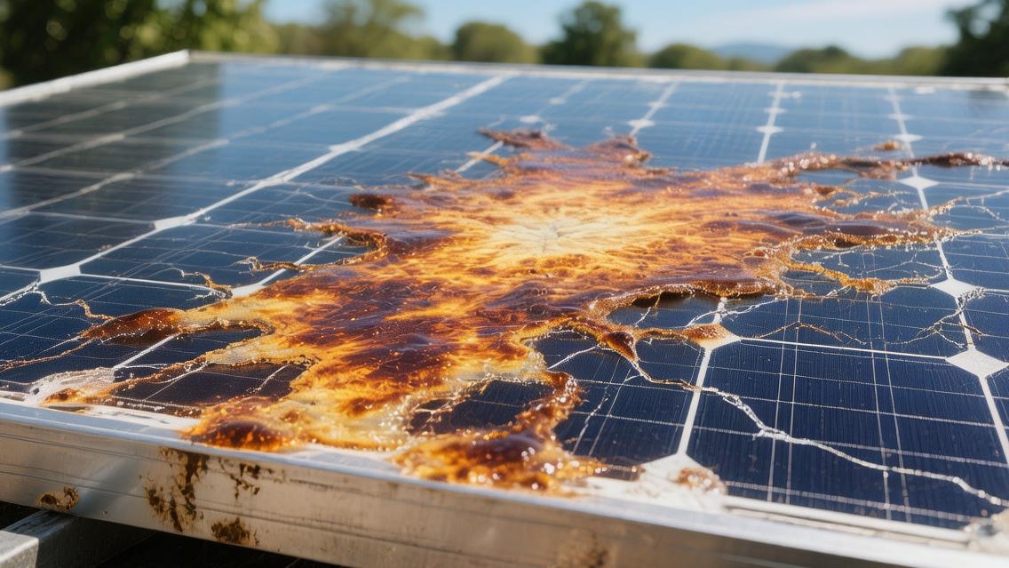
What happens when a solar cell is overcharged
Overcharging will cause the cell voltage to exceed the standard (e.g., Lithium-ion > 4.2V), triggering high temperatures above 60℃ and shortening the lifespan by more than 50%.
This will cause electrolyte depletion, cell bulging, and even fire risks.
It is recommended to install a PWM/MPPT controller for precise voltage control to ensure long-term safe operation of the system.
Primary Victim
Electrolyte is Decreasing
When the charging voltage of a 12V lead-acid cell exceeds the gassing threshold of 14.4V, 98% of the redundant electrical energy inside the cell will be used to electrolyze water instead of performing chemical energy conversion.
Under a continuous high voltage of 15.5 V, every 1 Ah of excess charge injected will electrolyze 0.33 grams of distilled water into 0.42 liters of hydrogen and 0.21 liters of oxygen.
This reaction will cause the electrolyte level to drop by 2 to 3 mm within 24 hours, exposing 5% of the area at the top of the plates to the air, resulting in oxidation.
· Electrolyte concentration increases from 1.28 g/cm³ to 1.35g/cm³, with acidity increasing by more than 15%.
· The safety valve opening frequency reaches 20 times per minute, resulting in the inability to release the internal pressure of 0.15 MPa.
· 30% of the micropores inside the separator will be blocked by generated bubbles, increasing the internal resistance by 12%.
· A single 10-hour severe overcharge will cause a permanent loss of 50 to 80 ml of electrolyte.
As the internal liquid volume continues to decrease, the ion conduction rate of the cell will drop by about 25%, causing the rated capacity of 100Ah to shrink to around 92Ah within 48 hours.
When the liquid level is 1 cm below the upper edge of the plates, the internal resistance heat loss will increase by 40%, causing the charge-discharge efficiency to drop from 90% to a level of 65%.
Plates Become Brittle
Under the strong action of a high-voltage electric field above 14.7 V, the lead dioxide particles on the positive plate will undergo a volume expansion of 10% to 15%, leading to a 30% decrease in the adhesion between the active material and the lead grid.
This physical structural damage causes the 0.5 mm thick grid to corrode and thin to 0.35 mm within 3 months, with the tensile strength decreasing by 45%.
When the grid corrosion ratio exceeds 20%, the current collection capacity of the plate will drop by 50%, causing the cold cranking current of the 12V system to plummet from 600A to below 350A.
· Lead sulfate crystals formed on the plate surface exceed 10 microns in diameter, with a coverage rate reaching 40%.
· The shedding rate of active materials increases at a rate of 3.5% per month in an overcharged environment.
· The thickness of the oxidation layer on the positive grid increases by 0.02 mm every 24 hours, blocking 5% of the current channels.
· The thickness of sludge at the bottom of the plates reaches 5 mm, leading to a 2% probability of a bottom short circuit.
This physical "softening" causes the voltage drop to instantly reach 1.5V to 2.0V when the cell is subjected to a 1C rate high-current discharge.
Plates originally designed to withstand 500 deep cycles will have only 60% of their structural integrity remaining after 10 overcharges, resulting in a residual cycle life of less than 150 cycles at 100% depth of discharge.
Voltage Out of Control
When the cell voltage of a 12.8V lithium iron phosphate cell reaches 3.7V, the SEI film on the negative electrode surface will begin to undergo microscopic decomposition with a thickness of 2 nanometers.
If the charging voltage is continuously maintained above 4.2V, the internal chemical reaction heat will generate an additional heating power of 50W to 80W.
In this environment, 25% of the electrolyte solvent inside the cell will undergo oxidative decomposition, producing more than 200 ml of flammable alkane gases.
In the process of the temperature climbing from 25°C to 60°C, the internal chemical reaction speed will grow by powers of 2.
· The cell voltage range expands from 0.02 V to over 0.35 V.
· The passive balancing power of the BMS system when detecting a 3.9V high voltage is only 50 mA.
· Internal pressure relief disks will physically break at 1.2 MPa, leading to 100% charging failure.
· The extraction ratio of lithium ions from the positive electrode material exceeds 95%, leading to an 8% collapse of the lattice structure.
This out-of-control state will cause the terminal voltage to rapidly drop from 14.6V to 13.2V or even lower within one hour after being fully charged, showing more than 15% of false capacity.
Due to the irreversible deformation of the lattice structure, the internal resistance of the cell will jump from 30 milliohms to 85 milliohms, causing a 3,000W inverter to automatically shut down due to undervoltage after carrying a load for 5 minutes.
Lifespan Cut by Half
An off-grid solar energy storage system of 48V 200Ah, if subjected to 1 hour of 58V overcharge daily, will see its expected 5-year design life rapidly shortened to 1.8 years.
This means the annual system maintenance budget needs to increase from 1200 RMB to 3500 RMB, with depreciation costs rising by more than 190%.
In a standard environment of 25°C, for every 0.1 V of overcharge, its 100% depth cycle count will decrease by 15% to 20%.
· Return on Investment (ROI) drops from an expected 18% to a low level of 6.5%.
· The average cost of storing 1 kWh of electricity skyrockets from 0.45 RMB to 1.15 RMB.
· The consistency deviation of the cell pack expands from 2% to 18% within 30 days.
· The annual availability of the system drops from 99% to 82%, increasing the risk of 15 unplanned power outages.
When 25% of the cells in the cell pack suffer overcharge damage, the discharge time of the entire pack will shrink from 8 hours to 3.5 hours.
To maintain the same electrical load, users have to pay an additional 4000 RMB or more to replace the entire cell pack, which extends the payback period of a solar project that could originally recover costs within 3 years to 7.5 years or even longer.
Money Down the Drain
Using a cheap PWM controller of 200 RMB instead of an MPPT controller of 800 RMB saves 600 RMB initially but will cause the cell pack worth 6000 RMB to fail prematurely within 24 months.
The 20% energy loss caused by overcharging means that one-fifth of the electricity generated by the solar panels is not effectively used, equivalent to 400 RMB of a 2000 RMB solar module being in an idle state.
This inefficient operation will increase the levelized cost of energy (LCOE) of the system by about 0.7 RMB, significantly reducing the economic competitiveness of the solar power plant.
· Cell replacement frequency increases from once every 2000 days to once every 650 days.
· Due to a 50% increase in cell internal resistance, the heat loss electricity during charging reaches 450 kWh annually.
· The appliance failure rate caused by system voltage fluctuations increased by 12.5%.
· The effective output ratio per 1000 RMB of investment decreases from 0.85 to a level of 0.42.
This means that over the entire 10-year system operation cycle, due to ignoring overcharge protection, the total expenditure will be 1.5 to 2.2 times higher than that of a scientifically managed system.
If the 50A charging current is precisely limited to the absorption voltage point of 14.2V, the cumulative throughput of the cell can increase from 120,000 kWh to 280,000 kWh, and the usage value per unit capacity is improved by 130%.
Physical Sign
Case Bulging
When the internal pressure of a 12V 100Ah cell exceeds the venting threshold of 0.07 MPa, and the safety valve cannot open normally due to a 15% crystallization blockage, the ABS plastic shell will bear a tension of 1.5 kg per square centimeter.
This pressure causes a physical deformation of 5% to 10% in the cell side walls, and the cell with an original width of 172 mm will expand outward by 8 to 15 mm.
Under an extreme overcharge voltage of 16.5 V, the volume of hydrogen precipitated inside the cell will reach 1.2 liters within 120 minutes, causing the tensile strength of the shell material to decrease by more than 40%.
Physical Deformation Data Reference:
· Shell thickness thinning rate: 3% to 7%
· Internal gas pressure peak: 2.5 PSI to 4.8 PSI
· Structural displacement: 3 mm to 12 mm per side
· Plastic deformation ratio: over 1.2 times the material yield point
This expansion will cause the pressure on the internal plate group to increase by 20%, compressing the separator between the plates by 0.2 mm and increasing the probability of an internal short circuit by 15%.
If you measure the length, width, and height of the cell pack, you will find that its total volume has increased by about 350 cubic centimeters, meaning the molecular structure of the shell has undergone irreversible permanent stretching.
Hot to the Touch
At an ambient temperature of 25°C, the surface temperature of a normally charging cell should not exceed 35°C, but in an overcharged state, internal thermal runaway will cause the temperature to rise by 4°C to 6°C every 10 minutes.
When the temperature hits the red line of 65°C, the chemical reaction rate inside the cell will be 3.5 times faster than the standard state, causing 20% of the active materials to undergo pyrolysis.
Under an infrared thermal imager, a high-temperature core zone with a diameter of 50 mm and a temperature as high as 85°C can be observed in the center of the cell, which is 25°C higher than the edge area.
Heat Loss Indicators:
· Heating power: 45W to 110W per cell
· Thermal conductivity decrease value: 0.5% per degree Celsius
· Thermal runaway trigger point: more than 40°C above ambient temperature
· Cooling time constant: extended by over 150%
Due to the high temperature, the conductivity of the electrolyte increases by 12%, and the charging current will additionally increase by 0.8 A to 1.5 A, forming a vicious cycle.
If the cell stays at a high temperature above 60°C for 5 consecutive hours, the softening degree of its internal sealant will reach 30%, resulting in tiny cracks with a width of 0.1 mm around the terminals.
Gassing and Leakage
Overcharging will cause 90% of the water electrolysis reaction inside a 12V cell to produce a large amount of mixed gas, with an hourly gas flow rate of over 600 ml.
These gases carry a 0.5% concentration of dilute sulfuric acid aerosol, and after being sprayed through the safety valve, they will leave a white crystalline area of about 20 square centimeters on the top of the cell.
If measured with a precision electronic scale, you will find that a 30 kg cell will decrease in weight by 150 to 280 grams after 24 hours of overcharging due to water loss.
Material Loss Statistics:
· Electrolyte loss rate: 5% to 12% per month
· Acid mist spraying initial velocity: 0.2 m/s to 0.8 m/s
· Liquid density change: increasing from 1.280 g/cm³ to 1.325g/cm³
· Safety valve opening frequency: 45 to 110 times per hour
This mass loss directly causes 15% of the upper area of the plates to be out of the electrolyte immersion, reducing the active materials effectively participating in the reaction by 185 square centimeters.
Due to the reduction in water, the sulfuric acid concentration in the electrolyte increases by 10%, which increases the oxidation speed of the plate grid by 2.5 times, causing the expected life of the cell to shrink from 1800 days to less than 600 days.
Charred Terminals
When the overcharge current generates a voltage drop of more than 0.3 V at the terminal post, the local ohmic heat will cause the temperature of the lead terminal to instantly reach 150°C or even higher.
At this high temperature, the contact resistance will skyrocket from 2 milliohms to 15 milliohms, resulting in a 10% power loss at the connection point.
Observations show that a 50-micron thick black oxide film will appear on the surface of copper terminals, which will cause the conduction efficiency to drop by 22% and increase the system's line loss expenditure by 0.5%.
Connection Part Parameters:
· Contact resistance increase: 300% to 750%
· Local temperature rise speed: 12°C per minute
· Oxidation layer thickness: 20 nm to 85 nm
· Bolt tightening torque loss: 15% to 30%
If overcharging continues for 72 hours, the plastic sealing ring around the terminal post will undergo 20% carbonization, losing 0.05 MPa of sealing pressure.
This physical damage will cause the internal acidic gas to climb along the terminal gaps, corroding the surrounding circuit board modules within 14 days and increasing the system's short-circuit risk by 8%.
Reduced Energy Storage
Overcharging will cause the diameter of lead dioxide particles on the plate surface to coarsen from 1 micron to over 5 microns, reducing the effective electrochemical surface area by 40%.
This change in physical structure results in a 100Ah cell being able to release only 75Ah of effective electrical energy after being charged with 120Ah, with the coulombic efficiency dropping from 95% to 78%.
Testing at a 0.5C discharge rate, the voltage will rapidly drop from 12.6V to 11.5V within 45 minutes, and the discharge platform is shortened by a time cycle of 35%.
Performance Decay Details:
· Effective reaction area reduction: 25% to 55%
· Coulombic efficiency loss: 12% to 28%
· Internal resistance jump: from 4 milliohms to 18 milliohms
· Self-discharge rate: increasing from 3% per month to 15% per month
This change in physical properties means that 25% of the active materials inside the cell have failed and shed to the bottom, forming a lead mud layer about 3 mm thick.
This layer of sediment will occupy 10% of the storage space at the bottom of the cell, obstructing the electrolyte circulation and causing the terminal voltage to be falsely high by 0.4V to 0.7V under the same charging current, further misleading low-end charging controllers with a 5% accuracy deviation.
Long-term Result
More Expensive Later
In a lead-acid cell system rated at 48V 400Ah, if it undergoes 2 hours of overcharge exceeding 59V daily, its original 1500 deep cycle life will be reduced to about 450 times within 12 months, a life loss ratio as high as 70%.
This sharp reduction in life means that during a 3-year operation cycle, users need to replace the cell pack 2.5 times, whereas in standard operation only 0.4 times is needed.
Based on a procurement cost of 8000 RMB per cell pack, the direct equipment depreciation cost caused by overcharging skyrockets from 222 RMB per month to 666 RMB, thereby increasing the storage cost per kWh by 3 times.
Since lead sulfate crystals on the plate surface will form an inert layer over 15 microns thick under 15.5 V high voltage, the internal resistance of the cell will gradually accumulate and increase from 4 milliohms to over 25 milliohms.
This increase in internal resistance will result in about 62.5 watts of additional ohmic heat loss per hour inside the cell under a 50A charging current.
In a 10-hour sunshine cycle, this is equivalent to wasting 0.6 kWh of electricity, accounting for 12% to 15% of the total daily production of a 1000-watt solar array.
Over time, this decrease in energy conversion efficiency will cause the total return on investment (ROI) of the system to slide from an expected 14% to around 4.5%.
Operating Indicators (3-Year Period) | Normal Charge Control (±0.1V) | Continuous Overcharge State (+1.2V) | Performance Change Magnitude |
Cumulative cycle count | 1200 times | 380 times | Decreased by 68.3% |
Available capacity retention rate | 88% | 32% | Dropped by 56 percentage points |
Average internal resistance (mΩ) | 4.8 mΩ | 22.5 mΩ | Increased by 368% |
Storage cost per kWh | 0.35 RMB/kWh | 1.18 RMB/kWh | Increased by 237% |
Number of unplanned system shutdowns | 2 times/year | 14 times/year | Increased by 6 times |
25% of the cells in the cell pack will suffer from serious individual voltage imbalance around the 18th month due to thermal runaway caused by overcharging, and the voltage difference will expand from the normal 0.05 V to more than 0.8 V.
This imbalance will cause the BMS system to frequently trigger current-limiting protection, causing a 5,000W inverter to automatically protect and cut off when the load rate reaches 30% due to instantaneous voltage drops.
Staying in this voltage fluctuation environment for a long time will shorten the lifespan of the filter capacitors inside the inverter by 40%, increasing the potential maintenance budget by about 500 RMB.
In a standard environment of 25°C, every time the cell undergoes severe overcharging, the shedding speed of its active materials will increase by 5 to 8 times, leading to an increase of 1.5 cm per year in the sediment at the bottom of the cell tank.
When this conductive sludge comes into contact with the bottom of the plates, it will trigger a self-discharge current of about 2.5A, causing the cell to self-drain 15% of its electricity every 24 hours even without a load.
This self-discharge phenomenon will be further intensified under 40°C high temperature in summer, causing the overall power supply reliability of the system to drop from 99.9% to below 85%.
Cannot Hold a Charge
Due to electrolyte dry-out caused by overcharging, the sulfuric acid concentration inside the cell will increase from 1.28 to over 1.40, which will cause the corrosion rate of the plate grid to increase at a rate of 35% per year.
This change in chemical properties results in a 100Ah cell being able to output only about 45Ah of actual electrical energy after being charged with 150% energy, and the effective depth of discharge (DoD) is forced to reduce from 80% to 30%.
For an off-grid household dependent on solar power, this means the backup power that could originally support two rainy days now can support less than eight hours, and system redundancy has disappeared by more than 80%.
Under high-density charge impacts, the SEI film inside the lithium cell will thicken by 5 to 10 nanometers, which will hinder the diffusion speed of lithium ions, causing a 20% to 30% drop in charge and discharge power.
Batteries that originally supported 1C rate fast charging can only support 0.3C slow charging after being damaged by overcharging; otherwise, the cell voltage will instantly soar to the warning line of 4.25V.
This performance degradation causes 40% of the electricity generated by the solar system during the 4-hour golden generation period at noon to be forced to be wasted by the charge controller because it cannot be stored rapidly into the cell.
Performance Degradation Parameters | Month 1 | Month 12 | Month 24 |
Charging acceptance efficiency (%) | 96% | 75% | 45% |
Rated discharge time (h) | 10.0 h | 6.2 h | 2.8 h |
Maximum charging power (W) | 2,400 W | 1,200 W | 500 W |
Shell deformation displacement (mm) | 0 mm | 4.5 mm | 12.8 mm |
This long-term physical damage will cause the voltage platform of the cell pack to shift downward as a whole, so loads that originally operated at 12.6V now have to face a low voltage input of 11.2V.
Low voltage will cause the current of inductive loads such as DC water pumps and refrigerator compressors to increase by 15% to 20%, thereby increasing the heat generation of these appliances' motors by 30%, and is expected to shorten the appliance life by more than 2 years.
Over the entire life cycle of 10 years for the system, because overcharge protection was initially ignored, the user's total expenditure on cell replacement, appliance repair, and energy loss will be over 22,000 RMB higher than a normal system.
Complete Waste
When more than 30% of the plate grids inside the cell are oxidized into non-conductive substances, the cell will completely lose its charge and discharge capability, and its residual value will only be the 5% lead material recycling price.
Due to shell bulging and electrolyte leakage caused by overcharging, the discount rate of such scrap batteries in the recycling market is usually as high as 40%, as the environmental cost for processing leaking batteries increases by 2 times.
In actual system operation, this means that a cell worth 1000 RMB a year ago will see its asset value rapidly shrink to less than 60 RMB after 18 months of incorrect use.
Due to acid mist corrosion generated by long-term overcharging, the contact resistance of supports, connecting cables, and combiner boxes around the cell cabinet will generally increase by 200% to 500%.
This invisible systemic damage will cause the voltage drop at the terminals to increase from 0.05 V to 0.4 V, making it so that even with a new cell, the overall efficiency of the system cannot recover to 90% of the initial state.
To repair the impacts brought by these corrosion, users usually need to spend an additional 800 RMB or so to replace damaged cables and galvanized brackets.
If we summarize this data into a long-term economic model, we can find that every 1 RMB invested in a high-quality charge controller can avoid 25 RMB of cell loss and 12 RMB of energy loss within 5 years.
This 1:37 input-output ratio proves that preventing overcharge is the link with the highest economic benefit in a solar system.
Ignoring this link will cause the actual LCOE of photovoltaic power generation to exceed 4 times the grid electricity price, making the originally environmentally friendly and energy-saving solution completely financially unfeasible.