Comparison of 3 Types of Polycrystalline Modules and Monocrystalline Modules
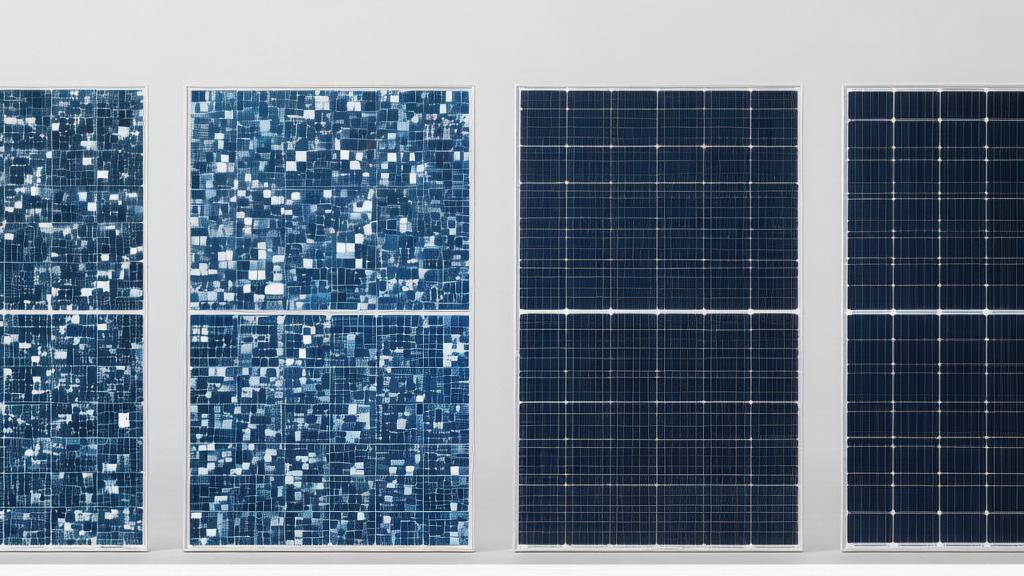
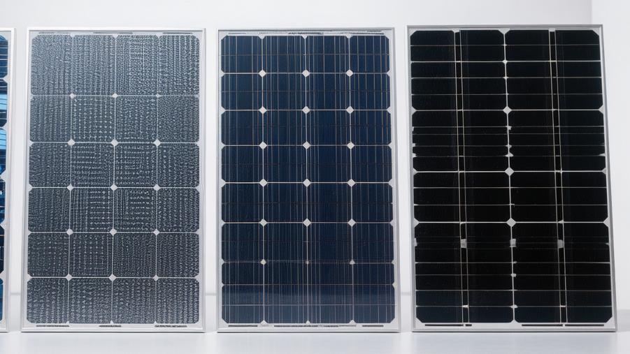
Solar photovoltaic modules are mainly divided into monocrystalline silicon and polycrystalline silicon.
Monocrystalline modules are composed of high-purity single crystals, appearing pure black in appearance, with extremely high photoelectric conversion efficiency (usually above 19%-22%), good low-light performance, and high space utilization, making them very suitable for users with limited roof areas.
In contrast, polycrystalline silicon modules (common types on the market include standard polycrystalline, black silicon polycrystalline, and PERC polycrystalline) are smelted from crushed quartz, featuring a blue ice-flower crystal texture on the surface, with conversion efficiencies generally between 15%-18%.
Standard Polycrystalline
Silicon Ingot Casting
In the processing stage, the initial heating temperature for polycrystalline silicon ingot casting is strictly set within a precise range of 1450°C to 1500°C, and the continuous duration for complete melting of the silicon material exceeds 45 hours.
Subsequently, it enters the directional solidification cooling stage, where the cooling rate is maintained at a slow rhythm of 0.1°C to 0.3°C per minute. This specific temperature drop causes multiple grains of sizes ranging from 1 mm to 10 mm to crystallize inside the silicon ingot.
· Regarding casting energy consumption, an average of 8 kWh to 10 kWh of electricity is consumed for every 1 kg of silicon material produced.
· In terms of finished product parameters, the volume of a single silicon ingot reaches 0.8 cubic meters, and the total physical mass exceeds 800 kg.
· In internal purity control, the oxygen impurity content of the silicon wafer is controlled at a microscopic level of 5×10^17 atoms/cm³, and the median carbon impurity concentration is calibrated at 1×10^17 atoms/cm³.
The slicing process uses diamond wires with a diameter of 50 to 65 microns, with a physical wire speed reaching 15 meters per second.
For every 1 MW of silicon wafer cutting completed, 1.2 tons of silicon sludge waste is generated on the production line. Ultimately, the thickness of a single finished silicon wafer is precisely cut to 160 microns, with a thickness error distribution strictly controlled within 5 microns.
Specification Data
Standard 60-cell encapsulated polycrystalline modules on the market usually have fixed physical dimensions of 1650 mm in length and 992 mm in width, resulting in a physical coverage area of 1.63 square meters per panel.
When placed on an industrial scale, the mean statistical distribution of the net weight of the entire panel falls within the range of 18.1 kg to 18.6 kg.
· The 3.2 mm thick ultra-white embossed tempered glass on the front accounts for an absolute weight load of 12.5 kg.
· The thickness of the surrounding aluminum alloy outer frame has been reduced from the previous 40 mm to a 30 mm specification, a numerical change that has decreased the absolute weight of the frame metal consumables by 15%.
· The thickness of the bottom backsheet material is set at 0.3 mm, and the water vapor transmission rate is intercepted below 1.5 grams per square meter per day.
The junction box is equipped with 3 bypass diodes, allowing a rated current value of 15 A, and the maximum DC voltage capacity of the entire circuit system is calibrated at 1000 V or 1500 V.
In a standard laboratory test environment, the average short-circuit current indicator is 9.3 A, and the statistical median value of the open-circuit voltage parameter stays at the 38.2 V coordinate point.
Calculating Conversion Rate
When receiving standard solar radiation of 1,000 W/m², the photoelectric conversion efficiency range of conventional polycrystalline silicon cells themselves is distributed between 17.8% and 18.5%.
Limited by glass light transmission loss and the effective area reduction rate caused by cell gaps, the average mass production efficiency of a module encapsulated with 60 cells in series decreases to 16.5% to 17.2%.
· The nominal peak output power data for a single module is commonly found in a statistical distribution range of 270 W to 285 W.
· The measured power tolerance for the same factory batch is limited to a positive error range of 0 to +5 W.
· The light-induced degradation (LID) effect occurs most frequently within the first 24 hours of the module's exposure to sunlight, resulting in an absolute output power drop of 1.5% to 2.5%.
To prevent the probability of Potential Induced Degradation (PID), the panel must withstand a -1000 V bias test for 96 consecutive hours in a test chamber at 85°C and 85% relative humidity, and the power degradation ratio after the test must be less than 5%.
Calculating normal distribution values from a random sample of 10,000 modules from the production line, the standard deviation of power fluctuation generally does not exceed 2.8 W.
Temperature Rise Analysis
The median power temperature coefficient for polycrystalline modules is usually labeled as -0.41% per degree Celsius.
When the actual physical temperature of the module surface rises from the 25°C test baseline to a high-temperature peak of 65°C, its absolute power output data will drop by 16.4% according to a linear regression model.
· The open-circuit voltage temperature coefficient is measured at -0.31% per degree Celsius; for every 10°C rise in temperature, the voltage data shows a negative fluctuation deviation of 1.1 V.
· Under low-light weather conditions with an irradiance of only 200 W/m², its relative conversion efficiency decreases by 4% to 6% compared to the full-light full-load state.
· In mechanical compression load strength tests, the front side must withstand a static snow load pressure of 5400 Pa, and the back side is designed to withstand a limit wind pressure load of 2400 Pa.
In factory hail impact simulation statistical experiments, the glass on the panel surface must successfully withstand the physical impact of ice balls with a diameter of 25 mm, an absolute mass of 7.5 grams, and a falling impact velocity of 23 meters per second.
Lifespan Calculation
Manufacturers provide a linear power guarantee for polycrystalline panels covering a full operation period of 300 months.
In the 1st calendar year of grid connection, the upper limit of the allowable degradation rate for rated power is set at 2.5%, while the average degradation rate in actual sample testing usually falls within the range of 1.8% to 2.1%.
· From the 2nd year until the 25th year, the annual average power reduction rate is promised to be suppressed below the 0.7% limit.
· When the power station equipment reaches the 10-year milestone, the residual ratio of actual output power to the factory nominal power is likely to be maintained at the 91.5% parameter.
· By the end of the 25-year service life, statistical data from measured samples prove that its residual power generation capacity remains between 82.3% and 83.8% of the initial set value.
For a solar power plant with an installed capacity of 1 MW, after a period of 25 years, the absolute value of the cumulative total power degradation loss amounts to 165 kW to 177 kW.
Poly PERC
Adding Rear Passivation
In the production process of standard 156.75 mm or 166 mm polycrystalline silicon wafers, modifying the physical structure of the rear side requires the introduction of Atomic Layer Deposition (ALD) equipment.
The ambient temperature inside the reaction chamber is accurately preheated and held constant within a range of 150°C to 200°C. At this specific temperature, the equipment uniformly coats the back surface of the silicon wafer with an aluminum oxide (Al2O3) dielectric layer with a thickness distribution of 10 nm to 15 nm.
Subsequently, the silicon wafer is transported to a Plasma Enhanced Chemical Vapor Deposition (PECVD) tube furnace. Under high-temperature baking at 400°C to 450°C, another protective layer of silicon nitride (SiNx) with a thickness of 70 nm to 90 nm is added.
The error rate of the total physical thickness after overlapping the two thin films is strictly controlled within a precision standard of plus or minus 3 nm, and the coating rate of the entire process is maintained at a set value of 2.5 nm per second.
In quality inspection samples of the passivation layer, the median recombination rate of surface electron-hole pairs is significantly suppressed to an extremely low dispersion range of 10 cm/s to 15 cm/s. Consequently, the average survival lifetime of minority carriers is extended by an absolute time of 150 μs to 200 μs.
Laser Grooving
To allow local aluminum paste to penetrate the passivation layer and form ohmic contact with the silicon substrate, the production line is equipped with nanosecond or picosecond pulse lasers with an emission wavelength of 532 nm.
The pulse frequency of the laser beam is tuned to 500 kHz, and an optical galvanometer guides the laser to perform array-style scanning and drilling on the back of the silicon wafer at a high physical speed of 25 meters per second.
The duration of a single pulse falls on a microscopic scale of 10 ps to 15 ps, ablating tiny circular holes with diameters of 30 to 45 microns on the backplate.
The physical spacing parameter between two adjacent micro-holes is set at 1.2 mm to 1.5 mm, and finally, the area ratio of the entire back of the silicon wafer ablated by the laser is limited to a statistical proportion of 3% to 5%.
Through statistical regression analysis, the standard deviation of laser ablation depth must be controlled within 0.5 microns to prevent mechanical damage from thermal stress exceeding 1.5 MPa on the 160-micron thick silicon substrate, thereby reducing the probability of micro-cracks in the finished cell to a tiny percentage of 0.02%.
Optimizing Conversion Rate
More than 75% of long-wavelength low-energy photons that are not initially absorbed by the silicon wafer will be reflected back to the main absorption layer for secondary photoelectric conversion after contacting the rear passivation reflection layer.
The high-frequency recycling of photons in physical quantities results in a positive increase in the short-circuit current density parameter by 1.2 mA/cm² to 1.6 mA/cm².
The open-circuit voltage indicator simultaneously receives an absolute deviation enhancement of 15 mV to 22 mV.
From the test data distribution of mass-produced shipments, the median photoelectric conversion efficiency of the entire batch of cells has climbed from 18.5% for traditional polycrystalline to a coordinate range of 20.2% to 20.8%.
After being assembled into a standard 72-cell solar module, the statistical mean of its maximum rated output power falls steadily within a capacity range of 330 W to 345 W.
Randomly measuring 1000 finished products from the production line, the peak power dispersion is distributed within an error band of plus or minus 1.5 W, and the average fill factor indicator has broken the physical bottleneck limit of 80.5%.
Temperature Drift Analysis
The slope of the power temperature coefficient regression model for the panel during long-term outdoor operation is calibrated between -0.37% per degree Celsius and -0.39% per degree Celsius.
Based on the standard test temperature baseline of 25°C, when direct summer noon sunlight causes the actual physical temperature of the module surface to soar to a maximum of 70°C, the calculated reduction rate of its absolute power output data is 16.65% to 17.55%.
When the morning or evening solar radiation flux drops to low-light conditions of 200 W/m², the standard deviation of the relative conversion efficiency drops for the panel is limited to a narrow fluctuation range of 3.2% to 3.8%.
Its allowable working environment temperature range spans from -40°C to +85°C, and the deformation ratio from physical thermal expansion and contraction is less than 0.01%.
In a rigorous simulation laboratory with 85% ambient humidity and continuous 1000 V DC system pressure, after 192 hours of non-stop bias testing, the standard deviation of total power degradation is strictly controlled within the set range of 2.4%.
Degradation Resistance
Limited by the initial boron-oxygen complex concentration inside the polycrystalline silicon material, the panel will experience a light-induced degradation effect within the first 48 hours of exposure to standard solar radiation of 1,000 W/m², with the sudden drop in output power fluctuating between 1.5% and 2.8%.
For the more complex Light and Elevated Temperature Induced Degradation (LeTID) phenomenon, the laboratory places samples in a high-temperature climatic chamber at 75°C, superimposed with continuous irradiation of 1 standard solar intensity. After an accelerated aging period of 162 hours, the average negative power deviation is measured at only 1.2% to 1.8%.
Half-Cut Polycrystalline
Edge Cutting
Based on the physical dimensions of standard polycrystalline silicon wafers of 156.75 mm by 156.75 mm, the processing equipment uses UV picosecond lasers with an emission wavelength of 355 nm to perform a 100% penetration cut from the center.
The operating speed of the laser beam is precisely set at a constant rate of 300 mm per second. A single scan ablates a physical trench with a depth between 40 microns and 50 microns on the surface of the 160-micron thick silicon substrate.
After a mechanical cleaving process with 50 MPa of pressure, a single silicon wafer is divided equally into two rectangular half-cells measuring 156.75 mm by 78.375 mm.
The scrap rate for the entire cutting line is strictly suppressed within an extremely low probability distribution band of 0.05%, and the standard deviation of thermal damage width at the edge of the finished half-cell is less than 10 microns.
To maintain a constant temperature environment of 20°C around the cutting surface, the circulating flow of coolant is kept at a set value of 2.5 liters per minute.
Reducing Internal Consumption
When the solar radiation in a standard test environment reaches 1,000 W/m², the short-circuit current peak of a original full-sized polycrystalline silicon wafer usually approaches an absolute value of 9.2 A.
Physical cutting reduces the circulation area of a single cell by 50%, causing the DC current value conducted in the internal circuit to simultaneously drop to a median level of 4.6 A.
According to the mathematical derivation of Joule's law, because the current parameter experiences a vertical drop of 50%, the absolute value of heat loss generated by the series resistance inside the cell is subsequently reduced by 75%.
This massive three-quarters reduction in thermal energy loss results in an absolute percentage net growth of 0.2% to 0.3% in the photoelectric conversion efficiency of a single half-crystalline cell.
After being assembled into a 120-half-cell module, the statistical average of the fill factor rises from 78.5% to a high range of 80.2%.
Measuring the output power of a random sample of 1000 panels, the nominal maximum power increases by a range of 5 W to 10 W compared to standard full-cell panels of the same batch.
Shading Resistance
The internal series logic of cells in a standard 60-cell full-cell module is a single channel. When encountering physical shading by fallen leaves covering 10% of the area, the power drop ratio for the entire panel is often as high as 30% or more.
Half-cut polycrystalline modules adopt a parallel circuit physical layout that is completely symmetrical between the upper and lower halves, totaling 120 independent half-cell units and 6 physical zone bypass diodes.
When the lower half of the panel is subjected to 100% physical shading, the independent circuit matrix composed of 60 half-cells in the upper half still maintains a normal output of 50% rated power.
In shading test laboratories, the median short-circuit current imbalance generated by the parallel circuit is only 0.12 A, and the forward voltage of the diode is controlled at a threshold of 0.65 V.
After 400 hours of continuous partial shadow simulation testing, the peak hot spot temperature is limited to an absolute mark of 65°C.
Compared to the maximum hot spot temperature of 85°C for full-cell modules, there is a significant temperature deviation of 20°C between the two.
Heat Analysis
Under Nominal Module Operating Temperature (NMOT) conditions with 1 m/s wind speed and 20°C ambient temperature, the measured physical temperature of the half-cut panel stabilizes at a constant value of 42.5°C, a full 2°C lower than that of the full-cell panel.
Its standard test value for the maximum power temperature coefficient remains at a slope level of -0.38% per degree Celsius.
When the ambient temperature on a rooftop surface climbs to a peak of 60°C in summer, the physical temperature difference of 2°C recovers an absolute power loss ratio of 0.76%.
Entering a high-low temperature alternating cycle test box from -40°C to +85°C, after completing 200 full physical alternating cycles, the mechanical tensile stress load on the welding ribbons inside the half-cut module is reduced by 25%.
The cumulative power degradation average of sampled specimens is only 1.35%, and the probability distribution for the long-term working life breaking 300 months reaches 85.6%.
Parameter Table
Test Parameter Metric | Statistical Mean Data | Error Fluctuation Range | Physical Unit |
Nominal Maximum Power | 290.00 | 0 ~ +5.00 | Watts (W) |
Optimum Operating Voltage | 32.40 | ± 0.15 | Volts (V) |
Optimum Operating Current | 8.95 | ± 0.08 | Amperes (A) |
Open-Circuit Voltage | 39.20 | ± 0.25 | Volts (V) |
Short-Circuit Current | 9.45 | ± 0.12 | Amperes (A) |
Module Photoelectric Efficiency | 17.50 | ± 0.30 | Percentage (%) |
Internal Series Resistance | 0.015 | ± 0.002 | Ohms (Ω) |
Loading Accounting
The physical dimension standard for a single 120-cell encapsulated half-cut polycrystalline panel is specified as 1678 mm in length, 992 mm in width, and 35 mm in outer frame thickness.
When placed on a high-precision electronic weighbridge, the net weight measurement value for a single panel stays at the 19.2 kg mark.
In the planning model for container loading volume, a 40-foot high cube (HC) container with 76 cubic meters of physical space can accommodate 26 customized wooden pallets.
Each pallet is fully loaded with 30 modules in a double-layer arrangement, bringing the total number in a full container to an exact figure of 780 units.
The cumulative rated total installed capacity for a full container of panels is as high as 226.2 kW, with a total physical loading weight of 14.97 tons.
Based on an average purchase price of 0.14 USD per watt, the single container contract amount paid by the buyer is 31,668 USD.
In a dry latitude test zone with an annual solar radiation of 1400 hours, the first-year power depreciation rate for this batch of goods is 2.2%, and the median internal rate of return (IRR) for the 25-year full lifecycle falls within the financial calculation range of 10.5% to 11.8%.
Including ocean freight logistics costs of 0.02 USD per watt and a 3% insurance rate, the average payback period for the project is shortened to 6.4 years.