Can Solar Panels Be Installed in the Rain?
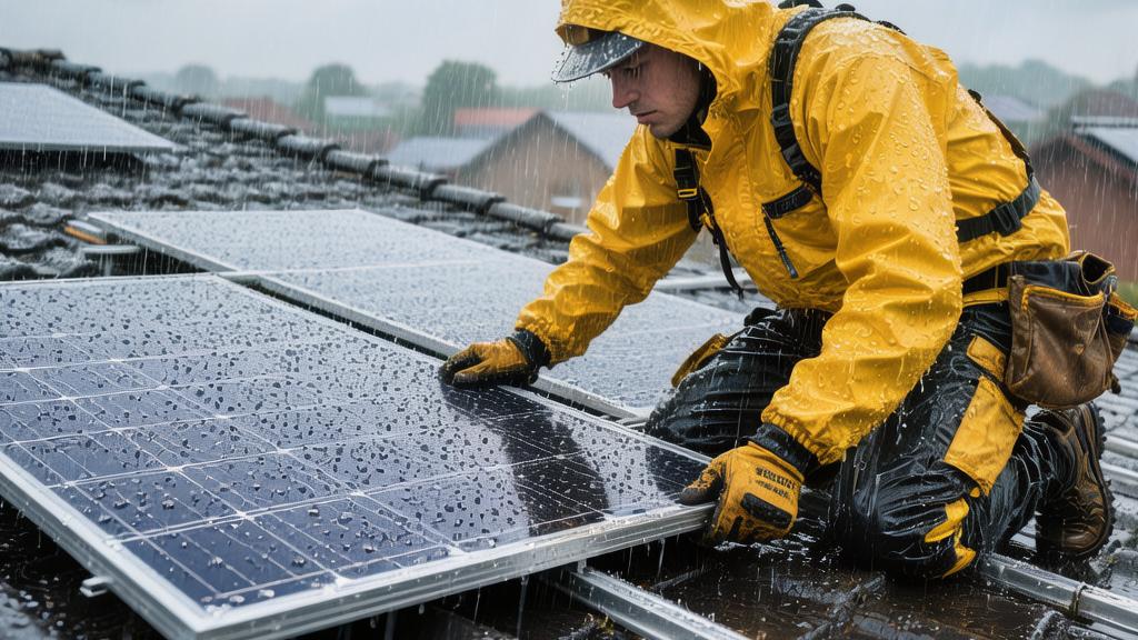
Solar panels are usually not installed on rainy days because both safety and quality will be affected.
Rainwater makes the roof slippery, increasing the risk of falls for construction personnel, while a humid environment may affect the sealing of electrical connections, reducing long-term system stability.
Most installation companies recommend construction in dry weather with temperatures between 5–35°C to ensure that bracket fixation and waterproofing seals meet standards.
Generally, the installation of a 5–10 kW home photovoltaic system takes 4–8 hours. If rainfall occurs, it is usually delayed to ensure installation quality and personnel safety.
Slips and Electrical Hazards
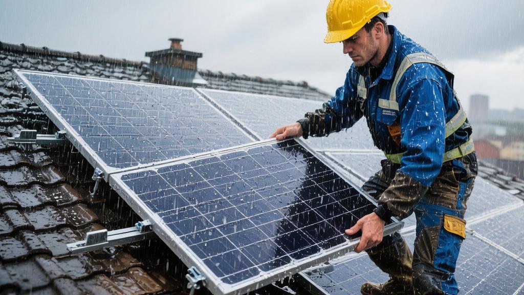
Slip Risk
Roof photovoltaic installations are usually carried out at heights of 6–12 meters. Residential roof slopes generally range between 15–35°. The average friction coefficient of a dry tile surface is about 0.65–0.75, while after rain, the friction coefficient of the same surface may drop to 0.30–0.40, a decrease of approximately 45%–55%.
When workers wear standard anti-slip construction shoes (sole rubber hardness of about 60–70 Shore A), the stable friction force generated by the contact surface of the sole in a dry environment is usually between 350–450 Newtons, while on a slippery roof, this value may drop to 150–220 Newtons, significantly reducing stability.
Taking a 5-person construction team as an example, where 2 people are moving and installing modules on the roof for a long time, they need to complete 6–10 module handling actions per hour on average. The size of a single module is usually about 2,279 mm × 1,134 mm, weighing about 27–32 kg.
When the module area reaches about 2.5 square meters, if a wind speed of 6–8 m/s occurs simultaneously, a lateral aerodynamic force of 25–40 Newtons may be generated on the module surface.
In a slippery roof environment, this lateral force will increase the offset of the body's center of gravity, and the sliding distance may increase from 0.2 meters to more than 1 meter.
Construction industry statistics show that in roof photovoltaic construction accidents, about 38% are related to slippery surfaces.
When the rainfall reaches more than 3 mm/hour, the thickness of the water film on the tile roof surface is usually between 0.2–0.5 mm. This water film will significantly reduce the contact stability between the sole and the roof.
The situation is even more pronounced for metal roofs, where the friction coefficient in a wet state can sometimes drop to below 0.25.
To reduce the risk of sliding, construction teams usually configure a dual-point safety rope system.
Common safety ropes have a diameter of 12–16 mm and a tensile strength generally in the range of 20–25kN, equivalent to a load capacity of 2000–2500 kg.
Safety ropes are connected via roof fixed anchor points. The anchor point installation position is usually 0.5–1 meter from the roof ridge, which keeps the safety rope angle between 30°–45° to reduce the impact force generated during a sudden fall.
The safety belt system itself weighs about 1.5–2.2 kg, and the extension length of the shock absorber is usually 0.8–1.2 meters.
If a fall occurs, the safety belt system can control the impact force to below 6 kN, while the impact force the human chest can withstand for a short time is generally about 8 kN.
This design can reduce the probability of serious injury to below 1%.
If the moisture content of the tiles exceeds 12%, or the metal roof surface temperature is below 20°C and the relative humidity exceeds 80%, the construction team will usually delay the module handling stage and first perform bracket positioning or ground assembly work.
Electrical Risk
The common residential photovoltaic module power is between 540W–560W, and the open-circuit voltage of a single module is usually 48V–52V.
When 20 modules are connected in series, the system DC voltage may reach 960V–1040V.
Air humidity in a rainy environment is usually in the range of 80%–95%. High humidity will reduce the surface resistance of insulating materials.
In a dry state, the surface resistance of the cable insulation layer is usually above 10 to the 12th power ohms, while when a water film forms on the surface, the resistance may drop to around 10 to the 9th power ohms.
The most common connection interface in photovoltaic systems is the MC4 connector.
The rated current of this connector is usually 45A, and the rated voltage is 1500V DC.
In a completely dry state, the average contact resistance is about 0.4–0.6 milliohms.
If moisture or dust appears inside the interface, the contact resistance may rise to more than 2 milliohms.
When the system current reaches 12–15A, the connection point may generate 0.3–0.5 watts of additional heat.
Operating for more than 3,000 hours in the long term, this local heat may cause the interface temperature to rise by 10–15°C.
Therefore, most installation companies will avoid making MC4 interface connections during rainfall.
In the actual construction process, after the modules are installed, the electrical connection stage usually takes 60–90 minutes.
If the roof is still wet, construction personnel will place the connectors into waterproof protection boxes and wait until the roof surface is completely dry to complete the final connection.
The inverter part also requires attention to the humidity environment. Common residential system inverters have a power of 5 kW–15 kW and a housing protection rating of generally IP65.
This rating means the device can withstand a water flow impact of 12.5 liters/minute for 3 minutes, but it is not suitable for long-term exposure to rain during the installation process.
Cables used during installation are usually 4 mm² or 6 mm² photovoltaic specialized cables.
This cable has a rated temperature of 90°C and an insulation thickness of about 1.2 mm.
If the cable ports contact rainwater before wiring, moisture may enter the small gaps between the copper conductors.
Even if the conductor moisture content is only 0.1%, long-term operation may accelerate oxidation, increasing resistance by about 1%–2%.
To reduce these problems, construction personnel usually take several measures on rainy days:
· Use rubber waterproof sleeves to protect connectors
· Lift unconnected cables 10–15 cm off the roof surface
· Use an insulation tester to check if the resistance value is higher than 500 megohms
These testing steps generally only take 5–10 minutes, but can significantly reduce the system's subsequent failure rate.
Roof Integrity and Waterproofing
Roof Drilling
Taking a common 10 kW system (about 25 modules of 550 W) as an example, the total area of the modules is about 52–58 square meters, and the total system weight is usually between 680–820 kg, including modules, aluminum alloy rails, and stainless steel fasteners.
To disperse the weight, construction personnel usually install 14–22 fixing points on the roof structural beams.
Each fixing point is connected to the roof wooden or steel beam via stainless steel bolts with a diameter of 8–10 mm.
Roof drilling depth is usually controlled at 55–75 mm, which ensures the bolt enters the structural beam by at least more than 40 mm.
If the drilling depth is insufficient, the tensile strength may drop from 5 kN to around 2 kN.
Common residential roofs may withstand an upward force of 700–900 Newtons per square meter of module at a wind speed of 30 m/s (about 108 km/h).
For a module with an area of 2.5 square meters, the upward force generated by a single module is approximately 1800–2200 Newtons.
Therefore, the bracket fixing points are usually designed with a density of at least 2 fixing points per square meter.
If construction occurs in rainy weather, a 0.3–0.6 mm water film easily forms on the tile surface during drilling.
This water film may cause the drill bit to slide, increasing the hole position deviation to 3–5 mm.
Excessive hole deviation will affect the flatness of the bracket, thereby increasing uneven stress on the module surface.
Construction teams usually use positioning fixtures to control hole position errors within 1 mm, ensuring that the rail horizontal deviation does not exceed 3 mm/3 meters of length.
Waterproofing Treatment
Every fixing point creates a hole in the tile or metal roof. Without a waterproof structure, rainwater may seep into the roof structure through gaps of 0.5–2 mm.
A common waterproofing method is to use an aluminum alloy base + EPDM rubber gasket. EPDM rubber gaskets generally have a thickness of 2–3 mm, and a stable seal can be formed when the compression rate is 20%–30%.
The temperature resistance range of EPDM material is usually -40°C to 120°C, and the UV resistance life can reach more than 20 years.
In a normal compressed state, the sealing area of each gasket is about 25–35 square centimeters, which is sufficient to cover all gaps around the bolt.
In addition to rubber gaskets, construction personnel will also use roof sealant around the holes.
Common sealants have a viscosity of about 300000–500000 centipoise, a curing time of 4–6 hours, and complete curing usually takes 24 hours.
After curing, the sealant layer thickness is usually 2–4 mm, and the tensile strength can reach 1.5–2 MPa.
This strength can withstand 1–2 mm of structural displacement caused by the thermal expansion and contraction of the roof.
If the roof surface moisture content exceeds 10%, the adhesion between the sealant and the tiles may drop by 30%–40%.
Therefore, many construction teams will use a heat gun or dry cloth to clean the hole area before installation, reducing the surface humidity to below 5% before applying the sealing treatment.
Roof Load-Bearing
A 10 kW residential system has a total weight of about 700 kg, distributed over a roof area of about 50 square meters, with an average load of about 14 kg/square meter.
Compared to ordinary residential roof design standards, a typical roof structure can withstand a uniform load of 120–150 kg/square meter.
From the perspective of structural load-bearing, the photovoltaic system only accounts for about 10%–12% of the roof's load-bearing capacity.
Module weight is not the only source of load; wind and snow will also increase the stress on the roof.
For example, in snowy areas, the common range for roof snow load is 80–150 kg/square meter.
When modules are installed on the roof, the module surface is smooth, and snow slides off faster. A lot of test data shows that snow stay time is reduced by 30%–50% on average.
At a wind speed of 25 m/s (about 90 km/h), each square meter of module may experience 400–600 Newtons of pressure change.
To resist this force, the bracket system usually uses aluminum alloy rails with a thickness of 3–4 mm. The rail material strength is generally 240–260 MPa, which can withstand a concentrated load of more than 1500 kg.
Wooden roof structures usually have a moisture content of 8%–12% in a dry state.
If it rains continuously for more than 24 hours, the moisture content may rise to 15%–18%.
An increase in moisture content will cause the compressive strength of the wood to drop by 5%–10%.
Seepage Probability
According to statistics from several roof repair companies, in a sample of more than 5000 residential photovoltaic projects, the proportion of roof seepage problems is about 0.4%–0.8%.
Typical roof tiles have an overlap height of 75–100 mm, and rainwater flows along the tile surface.
If the fixing point is located within 30 mm above the tile overlap area, water is more likely to enter the roof structure along the bolt position.
Therefore, many construction standards require fixing points to be at least 40 mm from the edge of the tile.
Under heavy rain conditions, the roof drainage speed is usually 1–2 liters/minute per square meter.
If the roof slope is above 20°, the time for water to pass through the bottom of the module is generally less than 3 seconds.
The bracket system maintains a 120–180 mm gap between the module and the roof. This space ensures smooth water drainage and reduces long-term rainwater retention.
Testing methods usually involve continuous spraying with a 15–20 liters/minute water flow for 10 minutes to observe if there are any signs of water seepage inside the roof.
If the sealing structure is installed correctly, most systems remain completely dry under this test.
The lifespan of photovoltaic modules is usually 25–30 years, and the design life of the roof waterproof structure also needs to be close to this cycle.
The average aging rate of EPDM gaskets is a thickness change of about 0.03 mm per year.
Calculated over a 25-year cycle, the gasket can still maintain more than 60% of its original elasticity.
Equipment Protection
The equipment involved in the installation process of a photovoltaic system mainly includes solar modules, inverters, DC cables, connectors, and installation tools.
In a rainy environment, these devices are exposed to air with humidity of 80%–95%. Without proper protection, the internal contact resistance, insulation performance, and long-term stability of the equipment will be affected.
A 10 kW residential system usually consists of 25 modules of 550 W, one 8–10 kW inverter, about 80–120 meters of DC cable, and 50–60 MC4 connectors.
The exposure time of these modules during the installation phase is usually 4–8 hours. If rainfall or roof water accumulation occurs simultaneously, equipment protection measures will significantly affect later operational stability.
Photovoltaic modules themselves have high protection capabilities. The protection rating of mainstream modules is IP67 or IP68, which can keep water out for 30 minutes in one meter of water.
The module surface uses 3.2 mm tempered glass, and the impact resistance usually reaches a pressure rating of 5400 Pa.
This pressure is equivalent to bearing about 550 kg of weight per square meter.
The water pressure generated by ordinary rainfall is generally between dozens and hundreds of pascals, far below the structural endurance range of the modules.
The module frame is usually 6063-T5 aluminum alloy, with a thickness of 1.2–1.5 mm, and the corrosion resistance cycle usually exceeds 25 years.
Short-term installation in a 90% humidity environment has almost no impact on the module body itself.
The MC4 connectors on the back of the modules have a rated voltage of 1500 V DC and a rated current of 45 A.
The internal contact resistance of the connector is usually 0.4–0.6 milliohms. If moisture or dust enters the connection port, the resistance may increase to 2–3 milliohms.
When the system current reaches 12–15 A, the connection point may generate 0.4–0.7 watts of local heat.
After long-term operation for 2000–3000 hours, this heat may cause the connector temperature to rise by 10–20°C.
To avoid this, construction personnel usually use rubber waterproof caps on unconnected interfaces. The internal diameter of the waterproof cap is generally 5–7 mm, which can completely cover the connection terminals.
Common residential system inverter power ranges from 5 kW–15 kW, and the equipment weight is usually 18–35 kg.
Inverter housing protection ratings are generally IP65. This rating means the device can withstand a water jet of 12.5 liters/minute for 3 minutes, but if exposed to rain for a long time during installation, the internal circuit boards may be affected.
The electronic module density inside the inverter is high. A 10 kW inverter motherboard has an area of about 250–350 square centimeters, with 200–400 electronic modules potentially distributed on it.
When air humidity exceeds 85%, a micron-level water film may form on the surface of the circuit board, which can cause the insulation resistance to drop from above 1000 megohms to around 100 megohms.
Therefore, construction personnel usually arrange the inverter installation under eaves or on the side of a wall and use a waterproof plastic cover film on the outside of the device.
DC cables used in photovoltaic systems are usually 4 square mm or 6 square mm copper core cables.
This cable has an insulation thickness of about 1.2 mm and a rated temperature of 90°C.
If the cable ports contact rainwater before installation, moisture may enter the small gaps between the copper conductors.
Even if the moisture content is only 0.05%–0.1%, the oxidation rate of the conductor surface during long-term operation may increase by 15%–20%.
Therefore, at the construction site, cable rolls are usually placed on racks at a height of 20–30 cm off the ground to avoid direct contact with ground water accumulation.
A common equipment protection list for a 10 kW residential installation team (4 people) is as follows:
Protection Item | Quantity | Specifications | Usage Time |
Module Connector Waterproof Cap | 30–40 pcs | Rubber material, 6mm internal diameter | Used throughout the pre-installation phase |
Inverter Waterproof Film | 1–2 pcs | 0.08mm thickness polyethylene | Installation phase 3–5 hours |
Cable Protection Bag | 3–4 pcs | 20–30 liter capacity | Storing unconnected cables |
Tool Waterproof Box | 1 pc | IP54 rating | Full-day use |
The cost of these materials is usually 30–80 USD, accounting for 2%–5% of the total 10 kW system installation cost (about 1200–1800 USD), but it can significantly reduce the probability of equipment getting damp.
Solar modules are usually transported in 30–36 pieces per pallet, with each module weighing 27–32 kg and a total pallet weight of about 900–1,100 kg.
Transport packaging usually includes paper corner protection + plastic waterproof film.
The waterproof film is about 0.06–0.1 mm thick and can keep the interior dry for more than 4 hours under a rainfall of 10 mm/hour.
If rain occurs at the construction site, construction personnel usually only unpack the modules needed for the day's installation, while the rest remain in their packaging.
Modules are usually placed on brackets with a tilt angle of 15°–20°, allowing rainwater to flow off the module surface within 2–3 seconds.
If modules are placed flat on the ground, the accumulated water thickness may reach 5–10 mm. Long-term water accumulation may increase the corrosion rate of the frame.
The corrosion rate of aluminum alloy in a humid environment is about 0.003 mm/year. Although this change is small, long-term water accumulation will still affect the appearance of the equipment.
Humidity changes also affect installation tools.
For example, electric wrenches usually use 18V lithium batteries with a capacity of 4–5 Ah.
In a 90% humidity environment, the cell terminal resistance may increase by 5%–8%, and the tool's output torque may drop by 2–4 Newton-meters.
The common torque range when installing bracket bolts is 18–25 Newton-meters. If the torque is insufficient, the long-term wind resistance of the bracket will decrease.
Therefore, construction teams usually use a torque calibration wrench to recheck the fixing points on rainy days.
The design life of a photovoltaic system is usually 25–30 years. Although the installation phase has only 6–10 hours of construction time, the requirements for equipment protection at this stage are very high.
If module connectors, cable ports, or the interior of the inverter are affected by moisture during installation, the efficiency may drop by 1%–2% after 5000–10000 hours of system operation.