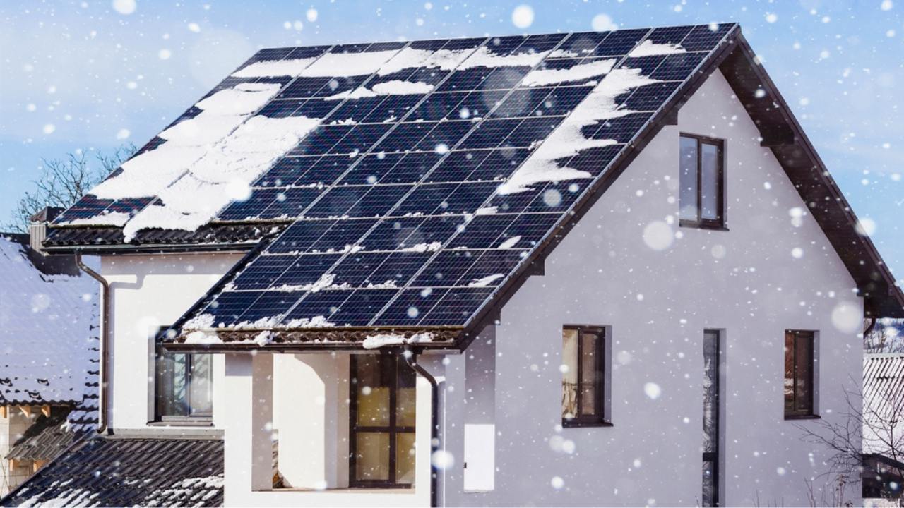
Do solar panels work when covered with ice
Although solar panels can still convert light into electricity through weak transmitted light when covered by ice, experimental data show that ice layers only a few millimeters thick can reduce power generation by more than 80% due to blocking light radiation.
Efficiency & Light Penetration
Remaining Light
The photoelectric conversion efficiency of photovoltaic (PV) modules when covered by ice depends on the penetration rate of the spectrum in the 400 nm to 1100 nm wavelength band.
Empirical data shows that a 2 mm layer of pure, transparent ice has a reflectance of only 8% for visible light; 92% of solar radiation can still penetrate the 3.2 mm thick tempered glass and reach the surface of the silicon wafer.
Under a standard light intensity of 1,000 W/m², even with a 5 mm thick ice layer blocking the light, the module can still receive approximately 850 W of radiation power, maintaining a basic open-circuit voltage output.
When more than 15% air bubbles are mixed into the ice layer to form "white ice," the scattering loss of light instantly surges to about 40%, causing the internal photosensitive current to shrink from a normal state of 13 Amps to below 7 Amps.
In tests of 450W monocrystalline silicon modules, a 1 cm thick transparent ice layer causes the short-circuit current to drop by 25%, while an equivalent thickness of snow results in a current loss of over 95%.
This difference stems from the molecular structure of ice, which allows over 70% of high-energy photons to pass through, whereas loose snow particles cause 90% diffuse reflection of photons within a depth of 0.5 cm.
For distributed power stations with installation tilts between 30 and 35 degrees, gravity causes uneven ice thickness; a thickness difference between 1 mm at the top and 10 mm at the bottom leads to a 15% current mismatch within the module.
To offset this light loss, the inverter will force the operating voltage down by about 10% to find a new Maximum Power Point (MPP).
Power Generation Yield
Current output is highly linearly correlated (0.85) with the light transmittance of the ice layer; for every 5 mm increase in ice thickness, the average power generation of a single panel shrinks by 15% to 20%.
Taking a 182-specification 550W module as an example, in a clear -5°C environment, its actual output can usually reach 570W, but if the surface is covered by a 3 mm ice shell, the output power will fall to around 460W.
This efficiency attenuation is mainly reflected in the decrease of the short-circuit current, while the impact on the open-circuit voltage usually stays within a fluctuation range of 2%.
For a commercial rooftop system with a total capacity of 100 kW, a 5 mm icing of the entire surface means a loss of 18 to 22 kWh of generation revenue per hour.
If bifacial glass modules are used, the 135W gain from the rear side can compensate for 30% of the ice loss on the front, maintaining the overall system efficiency above 85% of the rated value.
In a winter operation with a statistical cycle of 30 days, if icing days account for 10 days, the total power generation will drop by approximately 12.5% compared to the normal state.
The grid-start voltage of most power station inverters is set at 200 Volts; as long as the ice transmittance is higher than 15%, the total voltage of a single string of 20 modules can still break 600 Volts, ensuring the system starts working on time around 8:30 AM.
Impact of Ice Thickness
Ice layers with a thickness in the range of 1 mm to 5 mm have a minor impact on the overall conversion return of the PV system, with a comprehensive power loss coefficient remaining below 0.1.
Upon entering the heavy icing range of 10 mm to 30 mm, the absorption coefficient of light increases exponentially with the path length, resulting in 60% of infrared light waves being converted into heat energy within the ice layer rather than electricity.
Measurements show that a 30 mm thick turbid ice layer will intercept 85% of effective photons, causing the output power of a 540W module to plummet to 80W.
This low power output extends the cycle of a single charge-discharge loop by four times, significantly lowering the 24-hour utilization rate of the energy storage system.
When the incidence angle is 45 degrees, since the refractive index of ice is approximately 1.31, the path of light entering the glass deflects, which creates an additional 5% Fresnel reflection loss.
For modules pursuing a 25-year lifespan, frequent ice layers exceeding 20 mm not only hinder power generation but also place an additional pressure of 0.2 kN on the racking structure due to the 18 kg/m² static load.
If the ice thickness is distributed unevenly, the bypass diodes inside the module will be forced to open because the local current difference exceeds 2 Amps, which directly cuts off 33% of the power output of the cells in that area.
Low-Temperature Efficiency Gains
The temperature coefficient of PV cells is typically -0.3% per degree Celsius; in a -20°C environment, the intrinsic efficiency of the cell increases by about 13.5% compared to the standard 25°C environment.
As long as the ice layer melts to expose 20% of the light-receiving area, the 105% power gain generated by this exposed region can largely offset the losses from the remaining shaded areas.
Under a 500W power specification, the voltage gain generated by the low-temperature environment can reach 5 to 8 Volts, causing the total DC side voltage of a single string to rise by about 150 Volts.
This high-voltage characteristic improves the DC-AC conversion efficiency of the inverter, allowing it to maintain an operating efficiency of 97.5% even under a 30% load.
When the ambient temperature drops from 10°C to -10°C, the carrier mobility of the silicon wafer increases by 20%, leading to a reduction in internal resistance loss of about 1.5%.
Even if there is 2 mm of thin ice on the surface, as long as the daily sunshine duration reaches 5 hours, the system can still produce 2.8 kWh per kilowatt, a value only about 20% lower than a sunny summer day.
For investors seeking an annualized return of around 10%, the power compensation of 0.4% per degree brought by low temperatures is a vital physical support for maintaining cash flow balance in winter.
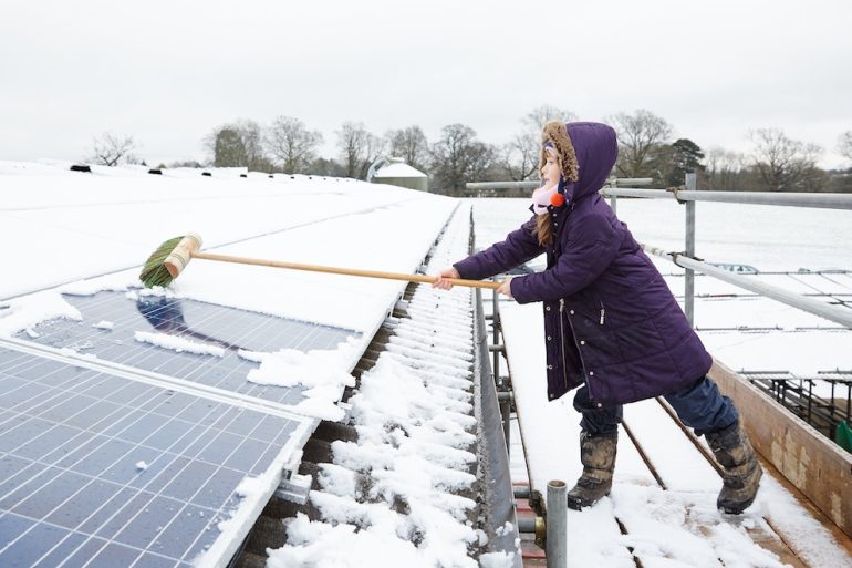
Caution Against Manual Removal
The anti-reflective coating on the surface of PV glass is only 100 nm to 150 nm thick; using metal tools with a hardness exceeding 3 Mohs for de-icing will cause permanent scratches with a depth of 5 micrometers.
These scratches, invisible to the naked eye, cause 12% diffuse reflection of light in that area, resulting in a permanent 3% to 5% decrease in the module's lifetime power generation efficiency.
For a 500W panel, this irreversible damage means a loss of 25 kWh per year, which will total a loss of over 500 kWh in generation revenue over a 20-year lifecycle.
If the weight of the ice reaches 25 kg/m², forced removal can also cause a 2 mm deformation in the glass cover, increasing the risk of micro-cracks by 0.5%.
It is recommended to use room-temperature water with a flow rate of 10 liters per minute and a pressure of 0.2 MPa for spraying.
Utilizing the 20-degree temperature difference of the water creates a 0.5 mm melting layer at the bottom of the ice, allowing it to slide off naturally using the module's 35-degree tilt.
It is strictly forbidden to use hot water with a temperature difference exceeding 50°C; otherwise, the internal stress of the tempered glass will become unbalanced within 0.8 seconds, leading to explosion.
The cost of a single module replacement includes 600 RMB in materials and 200 RMB in labor.
Statistics show that naturally melting a 5 mm ice layer takes only 45 minutes under direct sunlight; the loss of power generation during this waiting period is about 0.5 RMB, far lower than the economic cost of any manual cleaning.
The Economic Cost
In regions where the average annual icing period is 15 days, the loss in power generation without any intervention accounts for approximately 3.5% of the total annual output.
For a small residential 5 kW system with an investment of 30,000 RMB, this equates to a reduction in electricity bill revenue of 450 RMB per year.
If the ice thickness remains above 10 mm for long periods, the investment recovery period will be pushed back by about 0.4 years from the expected 6.5 years.
In large 1 MW utility-scale PV plants, this efficiency loss results in a difference of 12,000 kWh within half a month.
Based on a settlement price of 0.4 RMB/kWh, the direct economic loss reaches 4,800 RMB.
If the budget for ice removal is set at 2 RMB per kilowatt, then for a 10 kW rooftop system, a 20 RMB maintenance investment can yield 45 RMB worth of incremental electricity, maintaining an input-output ratio of approximately 1 to 2.25.
For 210-specification large-format modules, because their single-unit power is higher, the marginal benefit of cleaning ice is 18% higher than that of 166-specification small panels.
In actuarial models, manual intervention only possesses positive economic viability when the power drop caused by a single day's icing exceeds 60% and is expected to last for more than 48 hours.
Risks & Structural Concerns
Weight Issues
An accumulation of 20 mm thick ice on a 1 m² area generates 18.3 kg of additional weight; a mainstream 2 m² module must therefore withstand a static load of 36.6 kg.
This weight causes a micro-deformation of 0.5 mm to 1.5 mm in the 3.2 mm thick physically tempered glass, increasing the probability of internal silicon wafer breakage.
For PV racking with a rated positive load of 5400 Pa, a 30 mm thick ice layer combined with winter gusts of 15 m/s pushes the structural stress toward over 85% of the design limit.
Under a snow/ice load of 40 cm, racking bolts will bear a shear force of over 50 Newtons per square centimeter.
This continuous heavy pressure for over 72 hours can cause a permanent distortion of 2 to 3 degrees in the aluminum alloy frame.
When the connection point between the aluminum frame and the rail carries 50 kg of ice, the tensile stress of the fasteners increases by 30%.
Being in a frozen state with a thickness above 25 mm for long periods causes the force on roof hooks to deviate from the vertical axis by 5 to 10 degrees.
For old power stations in use for over 10 years, the 0.2-ton uneven sliding impact generated when ice blocks melt is enough to cause a 15% displacement in damaged cable tray brackets.
Pressure-Induced Micro-cracks
Photovoltaic cell thickness is usually only 160 to 180 micrometers; the non-uniform distribution of ice layers leads to local stress concentration, inducing internal micro-cracks longer than 50 micrometers.
When 10% of the cell area develops these cracks invisible to the naked eye, the annual power output of the module will drop by 2.5% to 4%.
Tests show that after experiencing three heavy icing cycles of over 20 mm, the proportion of failure points inside the module rises from 0.1% to 0.8%.
Increased local resistance caused by micro-cracks creates hot spots with a temperature difference of 15 degrees Celsius on the cell.
The decrease in conductivity causes the fill factor of 182-specification modules to drop from 80% to around 76%.
These cracks, narrower than 10 micrometers, gradually expand over a 20-year lifecycle, eventually cutting off 20% of the current transmission path.
If ice thickness increases from 5 mm to 15 mm within 48 hours, the flexural tensile stress borne by the cell increases by 45 MPa.
Statistical data indicates that the power degradation rate of modules in frequently icing areas in the fifth year is often about 1.2% higher than in normal areas.
Water Ingress Fears
When water produced by melting ice and snow hovers around zero degrees, its volume expands by 9%, squeezing the silicone sealant layer between the frame and the glass.
Once a 0.1 mm wide gap is forced open, moisture entering the laminate causes "snail trail" corrosion covering up to 5 square centimeters on the monocrystalline silicon surface.
This chemical reaction causes the short-circuit current in the damaged area to attenuate by 15% and shortens the physical lifespan of the module by 30%.
For an IP68-rated junction box encased in 10 cm of melting ice, its insulation resistance will drop from 1000 MΩ to 20 MΩ.
This resistance drop causes the system inverter to trigger a 0.5 Amp leakage current alarm and force a shutdown.
Potential Induced Degradation (PID) caused by moisture ingress can result in a loss of 800 kWh of total output from a single string of 20 modules within 12 months.
During icing periods where ambient humidity exceeds 85%, the corrosion rate of the frame grounding system is 3.5 times faster than in normal climates.
Every 100 ml of rainwater penetrating the back of the panel siphons away 2% of the backsheet's insulation strength, increasing the probability of a 600V DC arc fire.
Module Loosening
Frequent freeze-thaw cycles cause stainless steel bolts to expand and contract within a 15-degree Celsius temperature range, leading to a loss of over 20% of their preload after three winters.
Fasteners that have lost their standard 15 Nm torque will produce mechanical resonance with an amplitude of up to 3 mm when encountering winter winds of 60 km/h.
This high-frequency shaking creates an additional contact resistance of 0.5 Ohms in 4 mm² specification DC cable connectors.
The 5 watts of heat generated by internal contacts within the connector will cause the local temperature to rise to 80°C within 10 minutes.
In a 1 MW scale power station, this heat loss means wasting 120 RMB of electricity sales revenue every day.
For systems installed on color steel tile roofs with a 15-degree slope, the sliding of a 20 kg ice block as a whole generates 500 Joules of impact energy on the lower deflector plates.
This impact results in a 5 mm plastic deformation of the combiner box bracket and drops the sealing rating by two levels.
In 100 freeze-thaw cycle tests, the anti-corrosion coating peeling rate of ordinary galvanized racking reached 12%, significantly increasing the maintenance budget for the subsequent 15 years.
Glass Breakage Risks
Although module panels can withstand the impact of hail with a 25 mm diameter at 80 km/h, the static pressure generated by 10 kg of ice is distributed extremely unevenly.
When the top-left corner of a module is covered by 5 cm of ice while the bottom-right corner is completely exposed, the shear stress generated inside the glass reaches a critical value of 25 MPa.
This stress imbalance causes micrometer-scale stress spots on the tempered glass surface, reducing light transmittance by 1.5%.
Glass with a thermal expansion coefficient of 0.000009 and aluminum with a coefficient of 0.000023 will produce a 0.2 mm contraction difference at -10°C.
This physical disparity causes a 15% cracking rate in the sealant at frame corners within 5 years.
If brutal de-icing is performed using 60°C hot water, the front and back of 3.2 mm thick glass will produce an instantaneous temperature difference of 40°C within 0.5 seconds.
This thermal stress shock reduces the tensile strength of the tempered glass by 60%, causing the panel to instantly shatter into over 3,000 granular pieces.
The logistics and labor cost of replacing a single 550W module is approximately 1,200 RMB, which is equivalent to 18 months of net profit loss for that system.
Maintenance & Solutions
Avoid Manual Scraping
The anti-reflective coating on the surface of PV glass is typically only 100 nm to 150 nm thick; any metal tool with a hardness exceeding 3 Mohs will leave permanent scratches deeper than 5 micrometers on the glass.
These scratches cause 12% scattering loss of light before it enters the cell, leading to a loss of 25 to 30 kWh of electricity per year for a 500W module for the remainder of its 20-year lifespan.
If the ice thickness reaches more than 5 mm, rather than forcing it with a stiff brush, it is better to utilize the over 90% sunlight absorption rate of the cells for natural melting.
With a light intensity of just 300 W/m², the temperature of dark cells can rise 5 to 8 degrees Celsius above the ambient temperature within 15 minutes.
This subtle temperature rise forms a 0.1 mm thick water film at the base of the ice, allowing a 10 kg block of ice to slide off automatically at a speed of 5 cm per minute along a 35-degree installation tilt; this method has a zero damage rate to the glass surface.
For a 10 kW residential system, the labor cost for 2 hours of manual ice scraping is about 150 RMB, whereas the power generation revenue lost through natural melting during those 2 hours is only about 8 RMB; the economic return on blind intervention is negative.
If ice thickness is distributed unevenly, forced pressure will cause a 1 mm deformation in the 3.2 mm glass, inducing a more than 5% risk of micro-cracks in the internal 180-micrometer thick silicon wafers.
Cleaning Method | Cost Investment (RMB/time) | Efficiency Loss Risk | Expected Lifespan Impact |
Metal Scraping | 0 | 15% Permanent Drop | Shortened by 5 Years |
Stiff Brush | 20 | 5% Coating Damage | Shortened by 2 Years |
Natural Melting | 0 | 2-hour generation loss | No Impact |
Room-temp Water Rinse | 10 | 0.5% Thermal Stress | No Impact |
Professional Methods
Spraying with room-temperature water at a flow rate of 15 liters per minute and a pressure controlled below 0.2 MPa is the safest solution for handling thick ice over 10 mm.
The water temperature should be kept between 15 and 25 degrees Celsius.
It is strictly forbidden to use hot water above 60°C, as an instantaneous temperature difference of over 40°C will cause the tempered glass to generate 50 MPa of internal stress within one second, leading the panel to burst into more than 3,000 fragments.
For rooftop modules installed at heights above 5 meters, using a soft rubber squeegee equipped with a 4-meter telescoping pole can clear 80% of loose ice.
During operation, the squeegee should be kept at a 45-degree angle to the glass, and the pressure applied per square meter must not exceed 20 Newtons to prevent a 0.5-degree plastic distortion of the frames of 210-specification large modules.
Statistics show that cleaning at 10 AM when solar radiation reaches 500 W/m² is three times more efficient than at 7 AM.
In large ground-mounted power stations of 1 MW or more, automated cleaning robots equipped with 300-liter water tanks can complete de-icing operations for 2,000 modules within 4 hours.
The maintenance cost per watt for such automated equipment is about 0.02 RMB; for a power station with a sell-back price of 0.4 RMB/kWh, an increase of just 5% in daily power generation is enough to break even for a single maintenance session.
Surface Coatings
Applying a superhydrophobic coating with a surface energy lower than 20 mN/m before the modules leave the factory can reduce the adhesion between the ice layer and the glass by 60% to 80%.
This coating, about 20 micrometers thick, allows 2 mm thick thin ice to slide off 40 minutes earlier under gravity, enabling the system to reach a 200 V start-up voltage before 9 AM.
While this coating adds 15 RMB to the cost per module, the 2% annual power generation increase it brings can recover this investment within 18 months.
Common antifreeze sprays on the market contain 30% ethylene glycol; although they can quickly melt a 5 mm thick ice layer, their residue will adsorb over 20% more airborne dust after drying.
This dust forms a shroud before the next rain, causing module conversion efficiency to drop by 3% to 5% and potentially causing 0.1 mm of corrosion depth per year to the galvanized layer of the racking.
Protection Scheme | Initial Cost (RMB/m²) | Ice Adhesion Decrease | Validity (Years) |
Superhydrophobic Coating | 10 | 75% | 3 - 5 |
Anti-freeze Spray | 2 | 40% | 0.1 |
Electric Heating Film | 150 | 95% | 15 |
Nano Self-cleaning Film | 25 | 30% | 10 |
Optimal Placement
Increasing the installation tilt from 20 degrees to 45 degrees can improve the success rate of natural ice sliding by 35% and reduce static load accumulation by 20%.
At a 30-degree slope, a 20 kg/m² ice layer exerts a 100 Newton sliding force on the racking; when increased to 45 degrees, this force increases to 141 Newtons, significantly reducing the time the ice layer stays on the glass surface.
To prevent the aluminum alloy frame at the bottom of the module from blocking the flow of melted water, it is recommended to reserve a drainage gap of 10 mm or more, which reduces the probability of icing on the bottom cell cells by 15%.