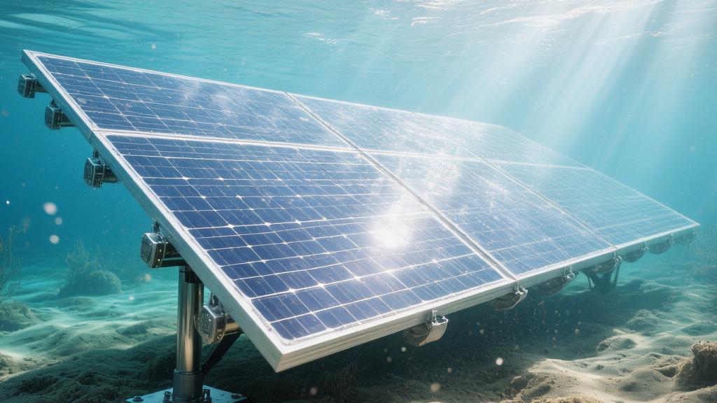
Can Solar Panels Be Used Underwater
Solar panels can indeed run underwater, but their efficiency will drop significantly. Light is absorbed and scattered as it passes through the water layer, leading to a weakening of light intensity.
Studies show that at a depth of 1 meter, the light energy loss is about 10%-20%; once the depth exceeds 5 meters, most infrared light is filtered, and the power generation efficiency is often less than 30% of that on land.
In addition, ordinary panels cannot withstand long-term underwater corrosion and pressure. Special transparent sealing materials (such as multi-layer fluoropolymers) must be used for vacuum encapsulation.
The Physics of Light in Water
Light weakens in water
In very clear oceanic waters (Case I water), the diffuse attenuation coefficient $k$ is roughly between 0.02 and 0.05, which means that for every 1 meter of descent, the light intensity is lost by approximately 2% to 5%.
However, in coastal or industrial operation areas (Case II water), due to the increase of suspended particulate matter, the k value will rapidly soar to above 0.15 or even 0.45.
This means that at a water depth of 3 meters, the light intensity may have dropped to around 30% of the surface level.
If the average irradiance on land is 1000 watts per square meter, at 5 meters underwater, due to the strong absorption of water molecules, the effective energy received by the photosensitive surface usually shrinks to below 120 watts per square meter.
This drop in energy directly causes a proportional decrease in the short-circuit current (Isc) of the photovoltaic modules.
For example, for a panel with a rated current of 8 amperes, the measured current at a depth of 5 meters can often only be maintained between 0.9 and 1.2 amperes, which places extremely high parameter requirements on the startup voltage and current lower limit of the backend Maximum Power Point Tracking (MPPT) controller.
Depth (m) | Typical Irradiance (W/m²) | Light Intensity Attenuation Percentage (%) | Estimated Current Output (A) |
0 (Surface) | 1000 | 0% | 8.0 |
1.0 | 720 | 28% | 5.6 |
3.0 | 350 | 65% | 2.8 |
5.0 | 115 | 88.5% | 0.9 |
10.0 | 25 | 97.5% | 0.2 |
Colors turn blue
Red light and infrared light with wavelengths between 600 and 700 nanometers are very sensitive to the vibrational energy levels of water molecules.
After entering two meters underwater, more than 85% of red light energy is converted into heat energy and dissipated.
This is very unfavorable for traditional monocrystalline silicon solar cells, because the optimal spectral response range of monocrystalline silicon happens to be between 600 and 1100 nanometers.
At a depth of about 10 meters, only the blue-green light portion of the spectrum between 400 and 540 nanometers remains.
Experimental data show that near the 450 nanometer wavelength, the absorption coefficient of water is the lowest, only about 0.01, which allows blue light to penetrate deeper.
In response to this physical characteristic, if amorphous silicon (a-Si) or III-V compound semiconductors (such as InGaP) with a wider bandgap are used, the energy capture efficiency in deep water will actually be higher than that of traditional silicon-based cells.
Because the Quantum Efficiency (QE) curve of such materials matches the underwater blue-green narrow-band spectrum better, although they are inferior to monocrystalline silicon on land, the output power per unit area after 3 meters underwater often surpasses it by more than 15%.
Spectral Band | Wavelength Range (nm) | Remaining Percentage at 5m Depth | Silicon Cell Response Strength |
Red/Infrared | 650 - 1100 | < 2% | Extremely Weak |
Yellow/Orange | 580 - 640 | 12% | Medium |
Green | 500 - 570 | 45% | Strong |
Blue/Violet | 400 - 490 | 78% | Extremely Strong |
Light scattering
In waters with turbidity reaching 5 NTU (Nephelometric Turbidity Units), the proportion of direct light in the incident light will drop by 40% after traveling 1 meter; all the rest is converted into diffuse light.
For land-based power plants, due to the strong direct light, a tilt angle deviation of 15 degrees may lead to a 5% power loss.
But underwater, because the proportion of scattered light is as high as 70% or more, the installation angle of the panels becomes less sensitive.
Even if the panel is tilted by 30 degrees, the fluctuation in the number of photons it receives is usually controlled within 2%.
However, scattering significantly increases the effective path length of light in water. For a vertical depth of one meter, the actual distance traveled by photons may reach 1.4 meters, which further exacerbates the energy attenuation rate before reaching the cell cells.
In estuary areas with high sediment content, when the suspended matter per liter of water is 50 mg, the Photosynthetically Active Radiation (PAR) will disappear by more than 90% at a depth of 0.5 meters.
Surface light reflection
When light enters water with a refractive index of 1.33 from air with a refractive index of 1.0, at an incident angle of about 45 degrees, approximately 2% of the light is reflected away.
When light is already underwater and about to enter the solar encapsulation glass or polymer layer with a refractive index of approximately 1.5, the situation becomes complicated.
Calculated according to the Fresnel formula, the reflection loss at the water-glass interface is smaller than that at the air-glass interface because the refractive indices of the two are closer.
This means that underwater, the reflection loss on the module surface drops from 4.2% on land to about 0.8%.
However, the refractive index of water causes the refraction angle when light enters the glass to become smaller, changing the path of photons within the silicon lattice.
If the glass surface is not smooth enough or contains micro-bubbles, the critical angle for total internal reflection of these bubbles underwater is only 48.6 degrees, which causes many photons to be totally reflected back into the water before they contact the cells.
Experimental measurements show that the gain effect of textured light-trapping glass underwater is 22% lower than on land because water fills the gaps between textures, weakening the originally designed refractive gradient effect.
Technical and Maintenance Concerns
Sealing must be sufficient
Underwater photovoltaic modules must maintain electrical insulation for more than 20 years in a fully submerged state, which puts strict requirements on their physical encapsulation.
Land modules typically use ethylene-vinyl acetate (EVA) film with a water absorption rate of about 0.5%, but at a depth of two meters underwater, constant hydrostatic pressure forces moisture to penetrate into the backsheet at a rate of 0.05 grams per 1,000 hours.
To solve this problem, underwater systems must switch to Polyolefin (POE) encapsulation materials, whose Water Vapor Transmission Rate (WVTR) is only one-tenth that of EVA.
When the module is immersed in seawater with a salinity of 3.5%, the insulation resistance between the internal circuit and the external water must be higher than 400 megohms.
Once the seal fails, voltage will rapidly leak through the conductive ion stream, leading to severe Potential-Induced Degradation (PID) within 48 hours.
Experimental measurements show that in a pressure environment of 0.5 MPa (equivalent to 50 meters water depth), if the junction box protection level is lower than IP68, the accumulation rate of internal condensation water will increase by 400%, directly burning out the bypass diodes.
Key Data Reference:
· Protection Level: IP68 (supports continuous immersion at 1.5 meters depth).
· Encapsulation Material: POE film (WVTR < 0.001 g/m²·day).
· Insulation Voltage: Must pass a 3000 volt DC test with leakage current less than 50 microamperes.
· Hydrostatic Pressure: Every 10 meters descent adds 1 standard atmosphere of pressure.
No electricity if dirty
Marine biofouling is the main cause of the collapse of underwater power generation efficiency. In nutrient-rich waters with temperatures of 22 to 28 degrees Celsius, algae, barnacles, and calcifying organisms will begin to colonize the glass surface within 72 hours.
Data show that when the surface attachment rate reaches 20%, the short-circuit current (Isc) of the photovoltaic panel will drop by 45%.
And when the attachment rate exceeds 50%, the spectral transmittance is almost zero, and the system basically stops working.
The current mainstream solution is to install low-frequency ultrasonic generators with power between 5 and 12 watts, preventing larvae attachment through vibrations of 20 to 40 Hz.
If manual cleaning is used, in shallow water of 1 to 3 meters, the recommended cleaning frequency per square meter is once every 15 days; otherwise, deposited sediment and excrement will form local hot spots, causing the local temperature of the cell cell to rise by 15 degrees Celsius within 10 minutes, causing permanent damage to the module.
Maintenance Details Parameters:
· Biofouling Rate: Summer coverage area increases by 1.5% to 3% daily.
· Ultrasonic Power Consumption: Accounts for 3% to 8% of the total system power generation.
· Cleaning Cost: Manual diving cleaning costs are approximately 60 to 100 USD/hour.
· Power Loss: Uncleaned modules drop in average power by more than 75% after 30 days.
Corrosion cannot be stopped
Standard 6063 aluminum alloy frames, without special treatment, will show pitting corrosion pits deeper than 0.5 mm within 12 months in seawater.
To extend the lifespan, underwater supports must use 316L grade stainless steel or hard anodized aluminum with a thickness of more than 25 microns.
Cable connectors are the most vulnerable part of the system and must use expensive neoprene compression molding technology; the cost of a single pair of connectors is typically between 120 and 180 USD, more than 50 times that on land.
In surface seawater with high oxygen content, the oxidation rate of metal surfaces is 8 times higher than inland. If the sacrificial anodes (usually zinc or magnesium blocks) are not checked regularly, the tensile strength of the support structure will drop by 30% after five years of operation, facing the risk of disintegration under typhoons or strong surges.
Practical Applications
Powering sensors
In marine monitoring and scientific research, various types of sensors deployed underwater (such as salinometers, turbidimeters, and dissolved oxygen sensors) usually require uninterrupted power support.
In the past, these devices mainly relied on built-in large-capacity disposable lithium batteries.
A water quality monitoring station with a power consumption between 200 and 500 milliwatts, if it collects and records data once every 15 minutes, a 100 Ah cell pack can usually only maintain 12 to 18 months of operation.
By integrating a micro monocrystalline silicon solar panel with an area of about 0.05 square meters on top of the device, in shallow water at a depth of 1.5 meters, even considering 70% light intensity attenuation, it can still generate about 1.2 watt-hours of electricity daily.
This amount of energy is sufficient to offset the daily self-consumption of the device and extend the system maintenance cycle from one year to more than six years.
In this model, the labor and vessel rental costs for a single field maintenance can save about 3500 USD. For a project with 50 monitoring points, the total operating expenditure (OPEX) over ten years can be reduced by more than 55%.
Parameter Item | Cell-only Solution | Underwater Solar Supplement Solution | Improvement Magnitude |
Device Power Consumption (mW) | 350 | 350 | - |
Maintenance Cycle (Months) | 14 | 75 | Extended 435% |
Cost for 10 Years per Point ($) | 28,000 | 9,500 | Lowered 66% |
System Voltage (V) | 3.6 | 3.7 - 4.2 | More stable |
For aquaculture monitoring
Modern automated aquaculture has extremely high requirements for real-time monitoring, especially in aquariums or cages 3 to 5 meters deep near the shore.
Automatic feeders, high-definition cameras, and aerator sensors all require stable low-voltage DC power.
A standard underwater monitoring camera power is about 3 watts; if turned on 24/7, it consumes about 72 watt-hours daily.
In sea areas with high clarity, installing an underwater photovoltaic module with a rated power of 80 watts, its measured output power at noon is about 12 to 18 watts.
By matching a 12 volt 20 Ah underwater sealed lead-acid or lithium iron phosphate cell pack, this system can achieve 100% energy self-sufficiency without external power supply.
This not only saves the cost of laying waterproof cables from the shore, which costs as much as 15 USD per meter, but also avoids the risk of cables being damaged by passing ships or organisms.
Data show that smart cages powered by underwater photovoltaics have a fault downtime 22% lower than wired power supply solutions, mainly due to the reduced frequency of short circuits caused by connector corrosion.
Slowing down metal rusting
Impressed Current Cathodic Protection (ICCP) is a key technology for preventing corrosion of underwater steel structures, pipelines, and pier pile foundations.
This technology requires applying a weak DC current to the metal structure to lower the potential of the metal below the protection potential.
Typically, each square meter of steel exposed to seawater requires 10 to 30 milliamperes of protection current.
For a medium-sized underwater pipeline interface, the required protection power is usually between 5 and 15 watts.
At a water depth of 0.8 meters, the spectral response of thin-film modules can better capture blue-green light, and its photoelectric conversion efficiency can be maintained at about 6.5%.
Compared to the traditional sacrificial anode method (which requires replacing expensive zinc or aluminum blocks every 3 years), the photovoltaic-driven ICCP system can extend the protection lifespan to 15 years, and by adjusting the controller output, the metal potential can be precisely controlled between -0.85 volts and -1.05 volts (relative to the saturated calomel electrode), with corrosion protection efficiency 40% higher than physical coatings.