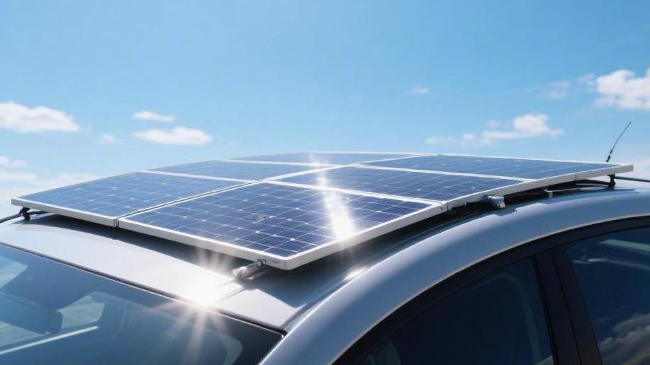
Can You Connect a Solar Panel to a Car | A Complete Guide
Connection is possible; it is recommended to select a 10-20W panel and install a 12V controller.
Connect the positive and negative poles of the panel to the controller, and then connect the controller to both ends of the cell accordingly to achieve safe supplementary charging.
Primary Use Cases
Long-term Parking
Many owners who leave their vehicles in a garage or at a campsite for 15 to 30 days find that the 12V 60Ah lead-acid cell voltage drops below 11.8V. This is primarily caused by a continuous parasitic draw of 35mA to 50mA from alarms and ECUs. A daily power loss of approximately 0.8Ah to 1.2Ah means a loss of 20% to 30% of total capacity within 20 days; installing a 10W to 20W solar maintenance panel can solve this problem.
A 10W panel, under 4.5 hours of effective daily sunlight, produces about 0.6A of current, translating to 2.7Ah of replenished power per day—which is 150% higher than the vehicle's own static loss. This trickle-style charging usually maintains a float voltage of 13.5V, which not only offsets self-discharge but also reduces cell plate sulfation by approximately 10%.
l A 10W monocrystalline silicon panel measures approximately 330mm x 240mm and weighs as little as 0.5 kg.
l Using 18 AWG connecting wire, the voltage drop over a 3-meter length is only 0.05 V.
l A Schottky diode with a reverse leakage current of less than 5µA must be connected in series within the circuit.
l Even on rainy days with 25% obstruction, the panel can still provide a faint current of 0.05A to 0.1A.
Camping with a Refrigerator
When using a 35-liter to 50-liter car refrigerator outdoors, the compressor's startup power is typically between 45W and 65W, with an operating duty cycle of about 30%. This means the refrigerator will consume 35Ah to 50Ah of power within 24 hours; without solar power, a standard 70Ah cell will drop to a 50% safety threshold within 12 hours. To achieve power balance, it is recommended to configure a 120W to 160W folding solar panel.
A 150W panel typically has a conversion efficiency between 21% and 23%, outputting a peak current of 8.3A at noon. If 5 hours of peak sunlight are obtained daily, the total power generation can reach about 750 Wh. After deducting 15% for system losses (including line loss and conversion loss), the actual power stored in the cell is about 50 Ah, perfectly covering a full day's consumption by the refrigerator.
l A 150W folding kit has an unfolded area of approximately 1.5 square meters and a folded thickness of only 5 cm.
l A matching 20A MPPT controller can efficiently convert 18V voltage into a 14.4V constant voltage charge.
l It is recommended to use 10 AWG pure copper wire with a resistance below 3.3 milliohms per meter to ensure transmission efficiency above 98%.
l Adding a 12.8V 100Ah LiFePO4 auxiliary cell as a storage medium provides a cycle life of over 2,000 times.
Offsetting Self-discharge
For modern vehicles equipped with 2K dash cams and various smart sensors, the power consumption after shutdown can soar to 80 mA or even 100 mA. Under this high-load standby, a small 45Ah cell only takes 7 days for the voltage to drop below 12.2V, reducing the startup success rate by 40%. By placing a 25W flexible solar panel under the windshield, a rated current of 1.4A can be provided.
Although there is a 15% light energy reflection loss through the glass—and explosion-proof window film can block an additional 30% to 60% of UV and infrared rays—tests show that in Southern summers, a 25W panel still outputs about 0.6A to 0.8A of effective current. This current level is 8 times the original vehicle's static consumption, enough to replenish the 0.8 Ah lost the previous night within 2 hours of an 8-hour sunlight period.
l A 25W flexible panel is only 2.5 mm thick and can bend 30 degrees to fit the shape of a dash mat.
l The operating temperature range is -40°C to +85°C, with a power reduction rate of approximately 0.4%/°C in a 65°C sun-exposed environment.
l When connecting via a cigarette lighter plug, confirm that the socket capacity is over 120W.
l A charger equipped with LED indicators can display charging status in real-time between 13.2V and 14.6V.
Outdoor Work
A 300W vehicle solar system can produce 15A to 18A of current per hour. Paired with a 1,000W pure sine wave inverter, it can achieve "charge while using" functionality under the sun. For a laptop with 60W power consumption, the redundant power from a 300W panel can also recharge a 100Ah auxiliary cell at a rate of 10% per hour. In abundant light, the system maintains a comprehensive conversion rate of over 85%; even when using two 40W drone chargers simultaneously, the cell voltage remains stable in a healthy range of 13.8V.
l A 300W system consists of two 150W rigid panels; the bracket installation angle is suggested to be set at the local latitude plus 15 degrees.
l The inverter's no-load current should be controlled below 0.5A, with a conversion efficiency above 90%.
l A 60A fuse should be used in the main circuit to prevent damage to the wiring if instantaneous short-circuit current exceeds 100A.
l The tempered glass surface of the solar panel must withstand the impact of a 25 mm diameter hailstone at a speed of 23 meters per second.
Protecting the Cell
Lead-acid batteries are most vulnerable to irreversible sulfation caused by long-term low power; when the charge is below 60%, hard lead sulfate crystals form inside the cell, causing capacity to drop by 15% to 20% annually. By using a solar panel for daily saturation charging, the cell can frequently stay at a 100% full charge state, which can extend the actual service life of the cell from 3 years to 5 years or even longer.
Investing in a 15W solar replenisher costs about 150 to 200 RMB, while the cost of replacing a start-stop cell is usually 800 to 1,500 RMB. Calculated over five years, the return on this investment is as high as 400%, because you not only save the money for a cell replacement but also avoid the risk of electronic throttle fault codes caused by insufficient voltage.
l Maintaining cell voltage above 12.7V every month can reduce active material shedding by 90%.
l The controller's overcharge protection function will automatically cut the circuit when the voltage reaches 14.6V, with an accuracy of ±0.1V.
l Cleaning the dust on the panel surface every six months can increase light transmittance by 5%, adding 0.2 A of current output.
l Monitoring via a Bluetooth module allows you to see voltage fluctuations at the 0.01V level on your phone.
The Essential Setup
Which Panel to Choose
A standard 100W monocrystalline silicon flexible panel typically has a photoelectric conversion efficiency between 21.5% and 23%, with physical dimensions of approximately 1,050mm x 540mm and a weight of only 1.8 kg to 2.2 kg. In contrast, the efficiency of polycrystalline panels is only about 17%, and their volume is over 20% larger for the same power. In actual lighting environments, a 100W panel has an operating current (Imp) of about 5.5A and an operating voltage (Vmp) around 18.2V.
If your roof space is limited, you can choose 120W high-density shingled panels, which shorten the length to under 1000 mm but produce 15% more energy per square centimeter than ordinary panels. When purchasing, you must check the backsheet material: ETFE coating is 3 times more weather-resistant than traditional PET, can withstand extreme temperature differences from -40°C to 85°C, and has a light transmittance as high as 95%, with a typical lifespan of 10 to 15 years.
"Under standard light intensity of 1,000 W/㎡, the 5.5 A current produced per hour by a 100 W monocrystalline panel can charge 27.5 Ah into the cell within 5 hours."
Install a "Brain"
Although a 20A PWM controller costs only 60 to 100 RMB, its charging efficiency is only about 70% because it forcibly drops the panel's 18V voltage to the cell's ~13V, causing 30% of the energy to be lost as heat. A 20A MPPT controller, priced between 180 and 450 RMB, uses an internal DC-DC conversion circuit to transform excess voltage into current, increasing overall charging efficiency to over 95%.
The controller needs to set three-stage charging parameters: the first stage is Bulk (constant current) charging until the voltage reaches 14.4V; the second stage is Absorption (constant voltage) charging, maintained for 2 hours to activate the plates; the third stage is Float, where the voltage drops to 13.8V to prevent excessive gassing. The static power consumption of a qualified controller should be controlled between 8mA and 12mA, so its consumption of the cell at night without sunlight is negligible.
How to Run the Wiring
The thickness of the wire determines the energy loss during transmission. For 100W to 200W systems, it is recommended to use 12 AWG or 10 AWG dedicated photovoltaic cables, with cross-sectional areas of 4 mm² and 6 mm² respectively. If the distance from the roof panel to the cell is 5 meters, the voltage drop produced by 12 AWG cable is about 0.15 V, keeping the loss rate within 1%; if cheap 18 AWG thin wire is used, the voltage drop will soar above 0.6 V, with a loss rate exceeding 4%, and the power generated by the panel will largely turn into heat in the wiring.
Connectors must use IP67-rated MC4 interfaces, which can withstand 30A of continuous current and have a contact resistance below 0.5 milliohms. When passing through doors or seals, flat shielded cables should be used to ensure 100% waterproof performance, preventing rain from seeping into the vehicle's computer modules along the cable.
"Using 6mm² pure copper multi-strand soft wire to connect a 150W system results in a power loss of only 0.7W over a 3-meter transmission distance, ensuring over 99% of the power enters the cell."
Add Protection
Fuses must be installed between the positive terminal of the solar panel and the controller, as well as between the controller and the cell. For a 100W system, a 15A DC fuse is recommended, placed within 15 cm of the cell's positive terminal. If an accidental short circuit occurs, the fuse will blow within 0.1 seconds, cutting off the instantaneous current from the cell, which can exceed 200 A.
Furthermore, since car engine compartments frequently maintain temperatures of 60°C to 90°C, the fuse holder must be made of flame-retardant nylon, and the cables should be encased in flame-retardant corrugated tubing. Given the high-frequency vibrations during driving, all wiring terminals must be cold-pressed and fitted with heat-shrink tubing, with a tightening torque of 3Nm to 5Nm to ensure contact resistance remains stable below 0.1 ohms over the long term.
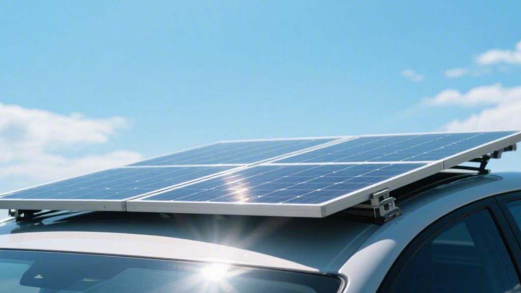
How to Secure It
Panel installation must account for the wind pressure caused by high-speed driving at 120 km/h. If using Z-type aluminum alloy brackets fixed to a luggage rack, each bracket needs to withstand an upward lift of about 10 kg to 15 kg; M6 stainless steel bolts with anti-loose nuts are recommended. If opting for direct adhesion to the roof, high-strength 3M VHB double-sided tape or modified silane sealant must be used, which has a shear strength of about 2.5 MPa.
Before pasting, the roof paint should be cleaned with 95% concentration alcohol to ensure no dust or grease remains. To facilitate heat dissipation, a 5mm to 10mm air circulation gap should be reserved under the panel, because for every 1°C increase in panel temperature, output power drops by about 0.4%. In summer afternoons when the roof temperature reaches 75°C, good ventilation allows the panel to output 10% to 15% more power.
"At a vehicle speed of 100 km/h, the wind resistance generated by a flat-mounted solar panel is approximately 150 Newtons; fixing it with four Z-type brackets provides an 8-fold safety margin."
Safety Warnings
Don't Reverse the Polarity
When connecting a 12V car battery to a solar controller, reversing the positive and negative poles is the most common cause of equipment damage. Although 90% of modern MPPT controllers claim to have reverse polarity protection, in practice, a surge current of 50A to 100A can still puncture the internal MOSFET transistors, causing the controller's failure rate to rise by over 40% after a misoperation.
The operating sequence of "cell first, then panel" must be strictly followed. If the solar panel is connected first, the controller's no-load voltage at the output end may reach about 20V without a cell load. Connecting the cell at this point can produce an arc discharge, creating a 0.2 mm thick oxide layer on the terminal surface and increasing contact resistance by more than 0.5 ohms.
Always use red for positive (+) and black for negative (-), and cover terminal ends with flame-retardant heat-shrink tubing at a 2:1 ratio. For systems over 100 W, the tightening torque of wiring bolts should be maintained between 4 Nm and 6 Nm. If the connection is loose, high-frequency vibrations during driving will cause the contact point temperature to soar to 120°C within 10 minutes, triggering the melting of surrounding plastic parts.
Fire and Overcurrent
Car engine compartments and interiors are high-vibration, high-temperature environments. Ordinary household wires will quickly harden and crack at temperatures above 70°C. Photovoltaic-specific cables meeting the UL4703 standard must be used, as their cross-linked polyethylene (XLPE) insulation can withstand high temperatures of 125°C.
The circuit must be configured with appropriate DC fuses, with a rated current 1.25 to 1.5 times the maximum output current of the controller. For example, a 20A controller should be matched with a 25A or 30A fuse.
Risk Location | Protection Module | Recommended Spec | Failure Consequence |
Between Panel and Controller | DC Circuit Breaker | 15A / 2-Pole | Partial hot-spot burnout due to shading |
Between Controller and Cell | Blade Fuse | 30A / ATO Type | Fire caused by short-circuit current >200A |
Inverter Input End | Bolt-on Fuse | 100A / ANL Type | Instantaneous overload blowing original wiring |
Cable Path | Corrugated Conduit | PA66 Nylon Material | Insulation damage and leakage due to friction |
Don't Overcharge
When the charging voltage of a lead-acid cell exceeds 14.7 V, violent electrolysis of water occurs, releasing a mixture of hydrogen and oxygen. In a sealed vehicle environment, if the hydrogen concentration reaches the 4.1% explosive limit, any static spark will lead to serious consequences.
Ensure the "Cell Type" setting on the controller is correct. The absorption charging voltage for sealed lead-acid batteries (AGM/GEL) is usually limited to 14.2V to 14.4V, while open flooded batteries can reach 14.6V. If an AGM cell is mistakenly charged in flooded mode, the water loss rate will increase by 0.5 grams per hour, resulting in a 30% capacity drop within six months due to plate desiccation.
If using Lithium Iron Phosphate (LiFePO4) as an auxiliary cell, you must confirm the controller has a low-temperature charging protection function for below 0°C. Forcing a charge at -5°C will cause lithium ions to form dendrites on the negative electrode surface, leading to internal short-circuits within 10 to 20 cycles and a replacement cost of over 1,500 RMB.
High-speed Wind Resistance
When installing a solar panel on the roof, dynamic wind loads at 120 km/h must be considered. A 1-square-meter rigid panel can generate 400 to 600 Newtons of lift at high speeds. If inferior suction cups or weak brackets are used, the probability of panel detachment increases by more than 5%.
For flexible panels, direct adhesion with structural adhesive is the mainstream solution. It is recommended to choose a modified silane adhesive with a tensile strength greater than 2.0 MPa and apply a 5 mm wide sealant strip around the panel edges to prevent airflow from entering underneath. If air enters under the panel, the resulting "kite effect" will rip apart double-sided tape with a strength of 1.5 kg/cm² within 3 minutes.
"At a wind speed of 100 km/h, the vibration frequency at the panel edge can reach 15 times per second. This high-frequency mechanical fatigue causes micro-cracks in monocrystalline silicon wafers, resulting in a 10% to 15% power decay within 12 months."
Leakage Inspection
If the MC4 connector is not locked tight, rainwater seepage can cause a ground leakage current of 10 mA to 30 mA. While this current won't immediately blow a fuse, it will accelerate electrochemical corrosion of the terminals, causing thick green rust on the contact points within three months.
It is recommended to perform a system inspection every 60 days, using a multimeter on the 200-ohm range to measure system ground resistance, which should be below 0.1 ohms. Simultaneously, check the temperature of the heatsink on the back of the controller; when working at full power at noon, the heatsink temperature should not exceed the ambient temperature by more than 30°C. If the temperature exceeds 80°C, it indicates insufficient heat dissipation space or an aging power tube, requiring immediate load reduction or the addition of a cooling fan.