Can i connect two solar panels to one charge controller
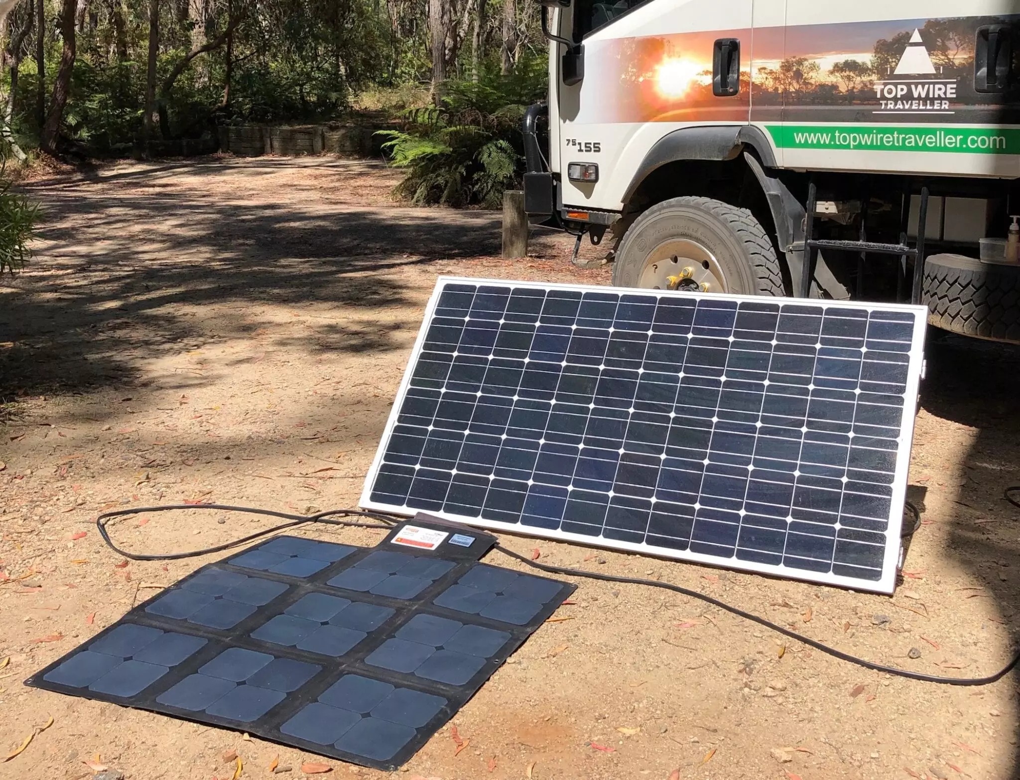
Yes, you can safely connect two solar panels to a single charge controller by ensuring the combined electrical specifications do not exceed the unit's maximum ratings, such as using a 30-amp MPPT controller to efficiently manage a dual 200-watt panel setup.
For optimal performance, connecting two identical panels in series increases the input voltage to approximately 40 volts, which reduces current-based heat loss and allows the MPPT algorithm to achieve conversion efficiencies up to 98%, provided the controller accepts an open-circuit voltage above 50 volts to account for temperature fluctuations.
Conversely, wiring in parallel doubles the total amperage to roughly 11 amps, requiring thicker 10 AWG copper cabling to prevent potential fire hazards, but this method ensures the system continues generating 50% power even if one panel is completely covered by shade.
Connection Methods
Series Connection
From an electrical parameter perspective, when two monocrystalline panels with specifications of 12V/100W (single panel Voc open-circuit voltage 22.5V, Imp working current 5.56A) are connected in series, the total system voltage will instantly double to 45V, while the current remains at the low level of 5.56A.
The characteristics of high voltage and low current provide a huge advantage in long-distance transmission. Assuming a photovoltaic cable length of 15 m, using standard 4 mm² (12 AWG) copper core wire, the voltage drop for a 36 V system is only about 0.3 V, with the line loss rate controlled within 0.8%.
In contrast, if it were low-voltage high-current transmission, the loss could be as high as 5% to 8%.
The buck converter circuit inside the MPPT controller can convert this 45V input voltage into a cell charging voltage of 13V to 14.8V with an efficiency of 97% to 99%.
Simultaneously, using the P=UI formula, it converts the excess voltage difference into additional charging current, allowing the output current to the cell side to potentially reach over 13A, which is more than 2 times the input current.
However, the biggest weakness of a series system lies in the "barrel effect." If one panel is shaded by 10% of its area, the output power of the entire series system doesn't just drop by 10%, but could plummet by more than 85% because the obstructed current channel forces down the overall amperage, unless the panel's built-in bypass diodes (usually 2-3 per panel) can quickly conduct within 0.02 s and bypass the shaded area, though this will also cause an instant 33% voltage loss.
Parallel Connection
Connecting the positive terminals together and the negative terminals together, then feeding the combined flow into the controller, is the survival solution for PWM controllers.
Physically, this must be done using a pair of "Y-type" MC4 branch connectors, which are typically made of tin-plated copper. The contact resistance must be less than 0.5 mΩ, and they should have IP67 waterproof and dustproof capabilities.
The electrical characteristic after parallel connection is that the voltage remains at the level of a single panel (about 18V to 22V), but the current directly doubles to 11.12A.
If you are using a PWM controller, since it lacks a voltage transformation function, it can only pull the panel voltage down to the cell voltage (such as 13.5V) through rapid switching chopping.
This means that out of the 18 V generated by the panel, 4.5 V of the voltage difference (about 25% of the energy) is directly "clipped" and wasted, with conversion efficiency only maintaining at 70% to 75%.
But parallel connection is not without merit; it has strong immunity to shading. If one of two parallel panels is completely covered by bird droppings, the other can still independently output 100% power. The total system loss is exactly 50%, avoiding the cliff-like drop seen in series connections.
Regarding wiring costs, parallel connection has extremely high requirements for wire cross-sectional area. To transmit 11 A of current over a distance of 10 m without letting the cable temperature rise by more than 10°C and the voltage drop exceed 3%, you must abandon ordinary 2.5 mm² wire and forcibly upgrade to 6 mm² (10 AWG) or even 10 mm² (8 AWG) dedicated PV wire, which directly increases the wiring budget by 40% to 60%.
Calculating Line Loss
Beyond connection logic, physical loss on cables is a hidden killer of final charging efficiency and must be precisely quantified using Ohm's Law (V=IR).
The resistance of PV cables is proportional to length and inversely proportional to the cross-sectional area.
Taking standard PV copper wire as an example, the resistance of a 4mm² cable is approximately 4.61 mΩ/m. If in parallel mode, the current is 12 A and the total line length (positive + negative) is 20 m, the total line resistance is 0.092 Ω. According to the formula P=I²R, the heat loss generated on the line will reach 13.2 W.
For a 200 W system, this means 6.6% of the electrical energy is directly turned into waste heat heating the air.
If switched to series mode, the current drops to 6A, and the heat loss under the same wiring is only 3.3W, with the loss rate instantly dropping to 1.65%.
This is why professional installers mandate series solutions for wiring distances exceeding 10 m.
Additionally, the contact resistance at connectors cannot be ignored. After three years of use, the contact resistance of a pair of standard MC4 plugs may rise from the initial 0.5 mΩ to 5 mΩ due to oxide buildup.
If there are four pairs of interfaces, in high-current parallel mode (12A), the voltage drop at the connectors alone can reach 0.24V, with a cumulative power loss of nearly 3W.
Regular inspection of connector temperature is a mandatory maintenance action; any connector with a temperature exceeding the ambient temperature by 15°C must be replaced immediately.
Installing Protection
Installing circuit breakers or fuses between the controller and solar panels is a hard requirement for fire prevention, and data selection must strictly adhere to NEC (National Electrical Code) standards.
For parallel systems, the sum of the short-circuit current (Isc) of two panels is approximately 12A. Calculated at a safety factor of 1.56 times (12A × 1.56 = 18.72A), you need to configure a DC circuit breaker with a rated current of 20A.
Never use an AC air switch as a substitute because DC arcs are difficult to extinguish. When an AC breaker cuts off high-voltage DC, a continuous arc lasting several seconds will be generated between the contacts, with temperatures reaching 3000°C, directly burning out the switch box.
For series systems, although the current is only 6A and it seems a 10A breaker would suffice, you must pay attention to the voltage rating.
After connecting two panels in series, the open-circuit voltage may reach 50 V. In extreme cold weather (-25°C), due to the negative temperature coefficient of semiconductor materials (about -0.3%/°C), the voltage will soar to above 55 V.
Therefore, the rated operating voltage (Ue) of the breaker must be above 100 V. It is recommended to directly choose a 2P 500 V DC dedicated miniature circuit breaker.
Checking Diodes
While the connection method determines the general direction, the bypass diodes inside the panel's junction box are the final line of defense at the microscopic level.
A standard 100W panel usually has 2 built-in Schottky diodes, dividing the cells into two strings.
In series mode, if the lower half is shaded, the corresponding diode conducts, creating a voltage drop of about 0.5V to 0.7V across the diode.
While sacrificing the output of this half of the cells, it preserves the current path for the other half and the entire series system.
If a diode breaks down and shorts (which has a probability of about 2% after a thunderstorm), the voltage of this panel will permanently decrease by half;
If the diode fails as an open circuit, when shading occurs, the shaded cells will generate a "hot spot effect" due to forced current flow, and local temperatures can soar to 150°C within 3 minutes, not only burning through the EVA backsheet but even potentially igniting dry leaves on the roof.
Therefore, before using old or second-hand panels for series-parallel networking, you must use a multimeter's diode setting to individually test every diode in the junction box.
The forward voltage drop reading should be between 0.2V and 0.5V. If the reading is 0 or infinity (OL), you must immediately spend 2 yuan to replace it with a diode of the same model; otherwise, the connected system is a ticking time bomb.
Check Specs
Check the Back
When you flip over a solar panel, the silver parameter label contains only two numbers that determine the life or death of the controller: Voc (Open-Circuit Voltage) and Isc (Short-Circuit Current).
The fatal mistake most people make is only looking at the nominal voltage of "12V." In reality, a monocrystalline panel labeled as "12V" usually has a Voc between 21.5V and 22.8V.
If you plan to connect two panels in series, the voltages must be added directly. Suppose you have two panels with a Voc of 22.5V; the base physical voltage for the series connection is 45V.
At this point, you need to check the value labeled "Max. PV Input Voltage" in the controller manual. This value for entry-level MPPT controllers on the market is usually 75V or 100V, while cheap PWM controllers usually only have 50V or 55V.
If your controller's voltage limit is 50V and your panel series voltage has reached 45V, this seems like there's still a 5V safety margin, but in electrical engineering, this is already on the verge of failure.
Because this 45 V is measured under Standard Test Conditions (STC, i.e., 25°C), the number will fluctuate drastically once the environment changes.
For parallel solutions, you should focus on Isc (Short-Circuit Current). If the Isc of a single panel is 5.8A, two in parallel will be 11.6A.
Although the controller label might say "20A," you must confirm whether this refers to "Cell Charging Current" or "PV Input Current."
Certain low-end brands' 20A rating refers to the output side, while the input side might be limited to 15A. Once exceeded, the input-side current-limiting resistor inside the controller will overheat.
A hard metric that must be remembered: The controller's maximum input voltage (Max PV Input) must always be at least 15% higher than the maximum possible voltage of the solar array on the coldest day. For a 100V controller, the safe input upper limit is actually 85V. Exceeding this red line is gambling with hardware lifespan.
Temperature Sensitivity
Semiconductor materials have a physical property called a "negative temperature coefficient," meaning the lower the temperature, the higher the solar panel voltage.
This parameter is usually labeled in the specifications as "Temperature Coefficient of Voc," generally ranging from -0.28%/°C to -0.33%/°C. This seemingly negligible percentage is the culprit behind burnt-out controllers.
Let's do a precise calculation: Suppose the standard Voc of a panel is 22 V and the temperature coefficient is -0.3%/°C. Standard testing is done at 25°C. If the morning temperature at your installation site can drop to -20°C, the temperature difference (ΔT) is 45°C (25 - (-20)).
The calculation formula for the voltage increase is: 45°C × 0.3% = 13.5%. This panel, originally 22 V, will have its voltage soar to 24.97 V on that cold morning.
If two are connected in series, the total voltage instantly changes from 44 V at room temperature to 49.94 V.
If your PWM controller's voltage upper limit is exactly 50V, as soon as the clouds part and direct sunlight hits, the internal capacitors will withstand a voltage close to the limit within 0.05 s, making it extremely easy to cause a breakdown short circuit.
Therefore, in cold regions (such as areas with latitude over 40 degrees), when choosing a controller, you must derive the maximum voltage based on the local historical minimum temperature.
For the aforementioned series system, an MPPT controller with a voltage rating of at least 75V or even 100V must be selected, rather than buying one right at the 50V edge.
Matching Wattage
In addition to voltage and current, the controller's "Max PV Input Power" is also a hard threshold, but it is much more forgiving than voltage.
When a rated 20A MPPT controller is connected to a 12V cell system, its maximum charging power is usually software-locked between 260W (13V × 20A) and 290W (14.5V × 20A).
If you connect two 100W panels (total 200W), this is well within the safe range, and the system operating efficiency will be very high.
But if you connect two 200W panels (total 400W), this is called "over-paneling."
This practice is physically allowed, provided the Voc does not exceed the limit. The controller will not explode, but it will initiate "clipping" protection, forcibly limiting the output current to 20A.
This means that at noon, when the sunlight is strongest, about 110 W to 140 W of the power generated by your 400 W panels is actively discarded by the controller, resulting in a lower Return on Investment (ROI) for hardware.
However, during rainy days or early morning/evening hours, 400W panels can generate twice as much electricity as 200W panels, which is crucial for power security in off-grid systems when light is insufficient.
As long as the voltage (Voc) does not exceed the limit, over-paneling the wattage by within 50% is usually safe and has practical significance.
For example, connecting 300W panels to a 20A controller may waste 40W during peak periods, but it can recover 30% more energy on cloudy days.
However, severe over-paneling on PWM controllers is strictly prohibited because PWM cannot adjust the operating point like MPPT; excess power will all turn into heat, causing the aluminum alloy heat sink on the back of the controller to exceed 75°C, accelerating silica gel aging.
Verifying Efficiency
Most MPPT controllers require the PV input voltage to be at least 2V to 3V higher than the cell voltage to initiate the maximum power point tracking function.
If you are charging a 12V cell, the voltage when the cell is full will reach 14.4V or even 14.8V. Adding the 2V startup voltage difference, the minimum PV input working voltage (Vmp) must be maintained above 17V.
If you adopt two panels in parallel, the Vmp of a single panel is typically between 17.5V and 18.5V, which is very close to the critical value.
Once encountering hot weather (the panel surface temperature can reach 65°C at noon in summer), the panel voltage will drop by about 15% to 20% according to the temperature coefficient, causing Vmp to fall to around 15 V.
In this situation, because the MPPT controller cannot obtain a sufficient voltage difference, it will directly stop MPPT scanning, or even stop charging, or degrade into a low-efficiency direct charge mode.
Therefore, for MPPT controllers, series connection (doubling the voltage to over 36 V) is almost the only correct choice. It ensures that the input voltage is much higher than the cell voltage under any high-temperature conditions, maintaining a conversion efficiency of over 98%;
Parallel connection is only suitable for PWM controllers which are not sensitive to voltage requirements, or as a compromise in environments with extremely severe shading.
Use the Same Solar Panels
Specifications Must Be Consistent
When connecting two solar panels, many users most easily overlook the "consistency" of the panels.
This doesn't just mean the nominal power (e.g., both being 100 W) should be the same; more importantly, the electrical parameters (Vmp working voltage and Imp working current) must strictly match, with the error range controlled within 0.1 V and 0.05 A.
If you connect a monocrystalline 100W panel (Vmp 18.5V, Imp 5.41A) and a polycrystalline 100W panel (Vmp 17.8V, Imp 5.62A) together, this tiny parameter deviation will lead to "mismatch loss."
In actual testing, this mixed connection causes the total system output power to be 5% to 15% lower than the theoretical value.
When the MPPT controller tracks the maximum power point, it will develop algorithm confusion due to the two different peak voltage points, preventing it from locking onto the true maximum power point.
It will spend most of its time hovering at a local sub-optimal solution, losing about 50Wh to 100Wh of power generation daily.
Synchronous Degradation
A solar panel used for five years will see the light transmittance of its tempered glass drop by 3%-5%, and the cell efficiency will also decay by 4%-6%.
This means an old panel labeled 100W may now have an actual output of only 90W (Imp dropping from 5.5A to 5.0A).
If you buy a brand new 100W panel (Imp 5.5A) and connect it in series, the 0.5A current of the new panel will be wasted.
According to infrared thermal imaging data, the high-performance new panel in a series system will have an average operating temperature 3°C-5°C higher than the old panel.
This additional thermal stress will accelerate the aging of the new panel, causing it to reach the aging level of a 5-year-old panel within 2 years, ultimately forming a vicious cycle.
Mixing Scenario | Connection Method | Physical Phenomenon | Estimated Efficiency Loss | Potential Risk |
Different Current (5.5A + 2.8A) | Series | Current limited to 2.8A | 40% - 50% | High-current panel overheats, bypass diodes conduct long-term |
Different Voltage (18V + 30V) | Parallel | Voltage clamped at 18V | 30% - 40% | Backflow circulation, low-voltage panel overheats, even fire risk |
Different Brands (Same Spec) | Series/Parallel | Mismatched internal resistance, dual-peak IV curve | 5% - 10% | MPPT tracking failure, accelerated long-term degradation |
Mixing New and Old (0 yr + 5 yr) | Series | Old panel limits new panel current | 10% - 15% | New panel affected by thermal stress, lifespan shortened by 30% |
Materials Must Be Unified
The power temperature coefficient of monocrystalline panels is usually -0.35%/°C, while polycrystalline panels are usually -0.45%/°C. When roof temperatures reach 65°C at noon in summer (40°C higher than the 25°C standard test environment), the voltage drop of polycrystalline panels will be much larger than that of monocrystalline panels.
If you connect these two materials in series, they might work normally at 20°C in the morning, but during the high-temperature periods at noon, because the optimal working voltage (Vmp) of the two drifts to different degrees, the voltage difference will expand to 1.5 V-2.0 V.
This will cause the MPPT controller to be unable to find an optimal voltage point that satisfies the characteristics of both panels simultaneously, forcing it to take a compromise value, which results in the power generation efficiency at the peak sun hour dropping by 8%-10% instead.
To ensure stable system operation for the next 10-15 years, it is essential to ensure that every panel comes from the same manufacturer and the same production batch.