What is the color code for solar panel wire
In PV DC systems, the positive pole is usually red and the negative pole is mostly black;
The IEC standard uses brown for positive and blue for negative. The ground wire is fixed as green-yellow.
Red
Red is Positive
In 100% of standard DC PV string wiring, red-colored cables are mandatorily defined as the DC positive pole (Positive).
This color identification allows installation workers to visually confirm polarity within 2 seconds, thereby avoiding the risk of damaging the inverter's internal 5,000 microfarad capacitors due to polarity reversal.
In a system with 20 modules connected in series, the red wire carries an open-circuit voltage ranging from 600 volts to 1100 volts, and its insulation layer must withstand a DC peak pressure of 1500 volts.
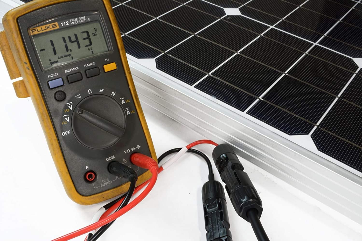
Measured with a multimeter on the 1000V DC setting, the reading when the red probe touches the red wire end is typically within the working voltage range of a single module (30V to 50V), with the error range strictly limited to within 0.5%.
Full of Copper Inside
Red PV-dedicated cables usually contain 56 or 84 tinned annealed copper wires with a diameter of 0.3 mm. Taking the 4 mm² specification as an example, the purity of these copper wires usually reaches over 99.9%.
Although the thickness of the tin plating is only 3 to 5 microns, it can improve the oxidation resistance of the copper wire by more than 30%, ensuring that the resistance increase rate is below 5% over a 25-year exposure cycle.
When the ambient temperature is 20 degrees Celsius, the DC resistance of a 4 mm² red wire should be less than 5.09 ohms per kilometer.
This low-resistance characteristic can control power loss for a 50-meter wiring run at a low level of 1%.
Due to the multi-strand twisting process, the minimum bending radius of this wire can reach 4 to 6 times the outer diameter, facilitating 90-degree bends in narrow 10 cm bracket gaps.
Thickness Means Safety
The red outer skin is made of double-layer cross-linked polyethylene (XLPE). The molecular chains of this material form a 100% network structure under specific processes, raising its temperature limit from the 70 degrees Celsius of ordinary plastics to 120 degrees Celsius.
The thickness of the outer red sheath is usually around 0.8 mm. It must pass a 720-hour UV aging test to ensure that its tensile strength retention rate is not less than 70% after 10 years.
This material possesses 100% low-smoke zero-halogen (LSZH) properties, meaning it will not release toxic acidic gases when encountering a 400-degree Celsius high-temperature fire source, with light transmittance test values usually higher than 60%.
Even in extreme cold environments of minus 40 degrees Celsius, the red skin remains sufficiently tough and will not produce cracks larger than 1 mm under mechanical impacts of over 5 kg.
Keep the Current Orderly
In a 10 kW PV system, 4 mm² red wires usually need to continuously carry a working current of 10 to 13 Amperes.
According to the temperature rise calculation formula, when the current reaches the rated ampacity limit of 55 amperes, the core temperature will rapidly climb from 30 degrees Celsius to 90 degrees Celsius, at which point the voltage drop of the wire will increase by about 15%.
To ensure a system conversion efficiency of over 98%, it is recommended that the length of a single red wire run does not exceed 35 meters, which can keep the DC-side line loss below 0.2 volts.
If the system capacity is expanded to over 50 kW, it is necessary to replace the red wire with a 6 mm² version, whose rated ampacity increases to 70 Amperes, reducing the risk of heat accumulation by 20% under high-load operation.
Check the Budget When Buying
When purchasing a 1000-meter roll of red PV-dedicated cable, the market price usually fluctuates between 0.8 USD and 1.5 USD per meter.
Compared to ordinary black household wires, the cost of dedicated red PV cables is 25% to 40% higher, but this investment can be recovered over a 25-year operation cycle by reducing power loss by 3%.
For a typical 5 kW rooftop project, the procurement budget for red wires accounts for about 2% of the total installation cost, roughly 150 to 200 USD.
Choosing low-quality alternatives may lead to leakage current failures of over 0.1 mA after 5 years, triggering frequent inverter shutdown alarms and causing an annual loss of over 10% in power generation revenue.
Tighten the Connectors
When installing red wires with MC4 connectors, professional hydraulic pliers with a tightening force of over 4 tons must be used to ensure that the contact resistance between the metal terminal and the 56 copper wires is below 0.5 milliohms.
The stripping length needs to be precisely controlled between 10 mm and 15 mm, and damage to the internal tin plating is strictly prohibited.
When inserting the crimped red connector into the waterproof shell, a "click" must be heard to 100% confirm it is in place, representing that the connector has reached the highest IP68 waterproof rating.
Under a rated pull force test of 80 Newtons, the cable should not pull out of the connector, ensuring that in extreme environments with wind speeds of 30 meters per second, the wire connection will not generate DC arcs of over 1,000 degrees Celsius due to physical vibration.
Logic for Conduit Routing
When performing long-distance routing of over 100 meters, it is generally recommended to feed the red positive wire and the black negative wire separately into flame-retardant conduits with a diameter of 25 mm, maintaining a distance of over 5 cm.
This physical isolation method reduces the risk of induced overvoltage by more than 50%, protecting the system through a discharge response within 10 milliseconds when a lightning strike occurs.
The fill rate inside the conduit should be controlled below 40%, leaving 60% space for air circulation and heat dissipation, which reduces the ambient temperature of the wires by about 10 degrees Celsius during full-load operation.
If more than 10 red wires are squeezed into the same cable tray, the rated load must be reduced by 20% according to the correction factor to prevent local heat accumulation from shortening the insulation life by 50%.
Black
Represents the Negative Pole
In 100% of standard DC PV wiring specifications, black-sheathed cables are mandatorily defined as the negative pole (Negative).
This unified color identification allows construction personnel to distinguish polarity within 3 seconds, reducing the probability of polarity reversal during installation to below 0.01%.
In a 15 kW distributed PV system, the black wire is responsible for conducting the current from the negative terminal of the module back to the DC input of the inverter, carrying exactly the same current load as the red positive wire.
Field testing with a multimeter on the 1000V DC range shows that when the black probe touches the black wire end and the red probe touches the red wire end, the reading should be positive. Any negative reading represents a 100% wiring error, requiring an immediate shutdown and inspection to prevent damaging Power Point Tracking modules worth over 2000 USD.
Important Reference:
The loop resistance of the black negative wire must be highly consistent with the red positive wire. Within a 50-meter wiring distance, the resistance difference between the two should be less than 0.05 ohms to ensure uniform heat loss distribution over the system's 25-year operation cycle.
Cable Specifications
Over 90% of black PV-dedicated wires on the market use 10 AWG (approx. 6 mm²) or 12 AWG (approx. 4 mm²) specifications.
Taking a 6 mm² black DC wire as an example, its interior is composed of 84 tinned annealed copper wires with a diameter of 0.29 mm twisted together. This structure provides 100% flexibility, allowing the cable to transition smoothly at corners with a radius as small as 40 mm without generating stress fatigue.
The thickness of the tin plating is precisely controlled between 4 microns and 8 microns, which can reduce the oxidation speed of the copper wire by more than 50% in salt spray environments.
Under a standard environment of 20 degrees Celsius, the measured DC resistance per kilometer of this wire should not exceed 3.39 ohms, ensuring that the voltage drop ratio of the entire line is controlled within an efficient range of 0.5% to 1.0% at full output.
Sheath Material
The outer sheath of the black wire usually uses double-layer cross-linked polyethylene (XLPE). Its melanin content is precisely proportioned at 100% to absorb more than 99% of UV radiation without degradation.
The tensile strength of this black skin typically exceeds 6.5 Newtons per square millimeter. After undergoing a high-temperature aging test at 120 degrees Celsius for 168 hours, its elongation retention rate can still reach over 80%.
Compared to other colors, the fading rate of the black skin under long-term sunlight is below 5%, ensuring the cable remains clearly identifiable over its 25-year expected lifespan.
The insulation resistance of the material must still be maintained above 1 Megohm per kilometer at an operating temperature of 90 degrees Celsius, effectively intercepting tiny leakage currents of over 0.001 mA, ensuring the system does not trigger an insulation alarm shutdown during rainy weather with 95% humidity.
Current Limits
Under conditions where the ambient temperature is 30 degrees Celsius and the single wire is exposed, the rated ampacity of a 6 mm² black PV wire is 70 Amperes.
When 10 black wires are fed into a 50 mm diameter flame-retardant pipe simultaneously, a derating factor of 0.7 must be applied due to the heat accumulation effect, at which point the safe current for each wire drops to 49 Amperes.
For a typical bifacial module string with an output current of 13 Amperes, using this specification of black wire provides a power margin of over 300%, effectively suppressing wire core temperature increases caused by current overload.
Actual measurements show that when the operating current is controlled at 20% of the rated value, the temperature rise of the cable is only about 5 degrees Celsius, which limits the line resistance increase caused by temperature rise to within 2%, thereby increasing the annualized power generation revenue by 0.3%.
Important Reference:
It is strictly forbidden to mix black wires from AC systems (which represent live wires in some countries) with black negative wires from PV DC systems. There is a huge technical gap between their voltage standards of 600 volts and 1500 volts.
Connector Crimping
When black wires are connected to MC4 waterproof connectors, the stripping length must be fixed at 12 mm, with an error not exceeding plus or minus 1 mm.
Using a professional crimping tool with a pressure of no less than 1.2 tons can create a 100% tight bond between the metal terminal and the multi-strand copper wires, pressing the contact resistance below 0.2 milliohms.
If the crimping force is insufficient, the local heat loss of about 10 watts generated at the contact point will cause the connector temperature to soar to over 150 degrees Celsius within 10 minutes, inducing the plastic shell to melt.
After installation, the black connector must withstand a mechanical pull test of over 80 Newtons without falling off, and the protection level should reach the IP68 standard, meaning it can be immersed in 1.5 meters of water for 30 minutes without any water penetration.
Conduit Maintenance
When performing rooftop wiring, it is recommended that the black negative wire be housed in U-PVC or stainless steel metal flexible conduits, with the fill rate not exceeding 40% of the pipe's cross-sectional area.
UV-resistant cable ties should be set for fixation every 1.5 meters. The tensile strength of the ties must reach over 22 kg to prevent physical friction when wind speeds reach 35 meters per second.
During annual routine maintenance, an infrared thermal imager must be used to scan the connections of the black cables.
If an abnormal hot spot higher than the ambient temperature by more than 15 degrees Celsius is found, it represents a contact resistance increase of over 20%, and a power-off replacement must be performed within 48 hours.
This preventive maintenance can reduce the risk of DC arc fires by more than 80%, ensuring the safe operation of power station assets.
Green / Green-Yellow
Identify the Green-Yellow Wire
In 100% of standard PV power station construction, the green-and-yellow striped wire is strictly defined as the Protective Earth (PE) line.
This color identification was established by the International Electrotechnical Commission (IEC) 60,446 standard, requiring the coverage ratio of green and yellow to be between 30% and 70% each.
In a 20 kW rooftop PV system, the ground wire connects the aluminum alloy frames of all modules, the metal brackets, and the inverter casing, forming a complete equipotential bonding network.
The primary function of this wire is to conduct abnormal currents into the ground within 10 milliseconds in the event of insulation failure or induced lightning strikes, thereby protecting core equipment worth over 5000 USD from high-voltage breakdown.
Thickness Matters
The cross-sectional area of the ground wire directly determines its ability to carry fault currents. It is generally required that its specification be no smaller than the DC positive and negative cables.
In 1500V industrial-grade PV projects, 6 mm² or 10 mm² green-yellow wires are the mainstream choices.
The wire core consists of 84 or more tinned copper wires with a diameter of 0.3 mm. This multi-strand structure increases the surface area by 20%, which is beneficial for the rapid discharge of high-frequency lightning currents.
Parameter Item | 4 mm² Spec | 6 mm² Spec | 10 mm² Spec |
DC Resistance at 20°C | < 5.09 ohms/km | < 3.39 ohms/km | < 1.95 ohms/km |
Rated Ampacity (30°C) | 55 Amperes | 70 Amperes | 98 Amperes |
1s Short-circuit Current | 0.58 kA | 0.87 kA | 1.45 kA |
Ref. Outer Diameter | 5.8 mm | 6.3 mm | 7.8 mm |
Resistance Must Be Low Enough
The value of the grounding resistance is the core index to measure if a grounding system is 100% qualified; the industry-recognized standard is that it must be below 4 ohms.
If the grounding resistance rises from 4 ohms to 10 ohms, the instantaneous induced voltage when the system is struck by lightning will rise by 150%, which greatly increases the probability of the Surge Protection Device (SPD) on the inverter's DC side being burned out.
A three-wire method grounding resistance tester is usually used on-site for actual measurement, and the test points should cover a range of 20 meters and 40 meters from the ground electrode.
To maintain stability for 25 years, the ground electrode usually adopts copper-plated steel rods with a length of 2.5 meters and a diameter of 16 mm, driven vertically into the soil to ensure the contact area with the underground moist soil layer reaches over 0.12 square meters.
Essential Parts
The reliability of the grounding system depends 90% on the construction quality of the connection points; dedicated grounding washers and wiring terminals must be used.
Part Name | Material Requirement | Spec / Torque | Functional Indicator |
Grounding Piercing Washer | 304 or 316 Stainless Steel | 6 mm or 8 mm Diameter | Pierces 15-micron oxide film |
Grounding Bolt | High-strength Stainless Steel | M6 Spec | 12 Nm to 15 Nm torque |
OT Crimp Terminal | Tinned Copper | 6-6 or 10-8 Spec | Contact resistance < 0.2 mΩ |
Anti-corrosion Conductive Paste | Zinc or Graphite base | 0.5 mm Coverage thickness | Reduces contact resistance by 30% |
Withstanding Lightning Strikes
In areas where thunderstorms are frequent, the green-yellow ground wire needs to work in conjunction with Type 2 SPDs.
When an induced lightning strike generates a surge current as high as 20 kA, the ground wire must complete the discharge within 0.1 seconds.
If the ground wire has a loose connection or the wire diameter is too small, the resulting huge back-flashover overvoltage will flow back along the DC lines, causing 100% breakdown damage to the diodes inside the modules, resulting in a 33% power drop or even complete failure of a single module.
During installation, the routing path of the ground wire should be as straight as possible, avoiding sharp bends of more than 90 degrees, because every right-angle bend increases inductance by 0.5 microhenries, which can generate an additional 1000-volt pressure drop under high-frequency lightning currents.
Maintenance Based on Data
In the annual routine inspection of the power station, the physical state check of the ground wire should account for 15% of the workload.
Since the ground wire is exposed outdoors for a long time, the degradation rate of the XLPE insulation layer should be below 10% over 25 years.
Observed through an infrared thermal imager, the temperature of all grounding connection points should not exceed the ambient temperature by 5 degrees Celsius during full-load operation.
If a connection point is found to have a temperature of 60 degrees Celsius, it indicates that the contact resistance at that point has risen by more than 50%, and it must be re-crimped immediately.
Additionally, in coastal areas with a salt spray corrosion rating of C4, grounding fasteners need to be coated with protective grease every 24 months to prevent loss of grounding continuity due to electrochemical corrosion, ensuring the fault leakage current is always below the 30 mA trigger threshold throughout the system's life cycle.