White spots under solar module glass are usually caused by a trapped void, contamination, poor bonding between layers, or delamination. What matters is not the color itself, but whether the spot stays the same or keeps changing. A small, stable mark is usually a very different case from a white area that grows, reaches the module edge, or appears together with corrosion, moisture, abnormal heat, electrical faults, or falling output.
Before looking for an internal fault, check the simplest possibility first: is the mark actually under the glass? Hard-water deposits, dried cleaning solution, dust, pollen, bird residue, and some glass-coating effects can all look white or cloudy. Once a surface mark has been ruled out, record the size, location, and any change over time.
| What you see | Likely possibilities | What matters next |
|---|---|---|
| Small round white dot | Void, trapped gas, or particle | Does it stay the same size? |
| Irregular cloudy patch | Loss of adhesion or delamination | Is it spreading? |
| White area touching the edge | Edge delamination | Is there moisture, corrosion, or growth? |
| White area beside a ribbon | Void, poor bonding, contamination, or corrosion | Is the metal discolored or hot? |
| Same pattern on many modules | Possible shared material or production issue | Do the modules share a batch or pallet? |
Is the Mark Really Under the Glass?
Start with the glass surface. Mineral deposits from hard water can leave pale rings or cloudy patches after drying. Cleaning residue, pollen, dust, and bird residue can look surprisingly similar from a distance.
Clean the module only as allowed by the manufacturer's instructions. Tongwei's PV module installation and maintenance manual includes cleaning and inspection requirements.
If the mark disappears after proper cleaning, there is no internal white-spot issue to investigate. If it remains in the same place and clearly appears below the glass surface, the next step is to look at its shape, location, and behavior.
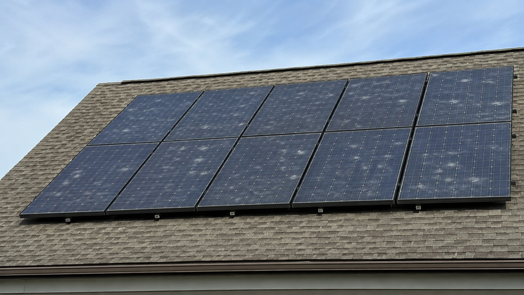
Viewing angle can help, but it is not proof. A thin gap inside the laminate can look bright silver from one direction and much weaker from another because reflected light changes with angle. Glass coatings can create a similar effect.
What Does the Pattern Tell You?
A solar module is not just glass over cells. Inside are the front glass, encapsulant, solar cells, metal interconnections, and a rear layer. Current solar module designs include both single-glass and dual-glass constructions, so the exact layer involved in a white spot depends on the module.
When those layers stay tightly bonded, light passes through with relatively little reflection. If a small gap develops, light hits an extra air/material interface and more of it is reflected back.
IEA PVPS reports that glass/air and EVA/air interfaces created by delamination have an interfacial reflectance of about 4%. That figure applies to the local interface. It does not mean a module with a white area automatically loses 4% of its total power.[1]
Small, round, and unchanged
A small round mark may be a trapped void or a particle left during manufacturing. If it has been visible since installation and looks the same years later, there is less evidence that the defect is actively spreading.
Shape alone is not enough to call it a bubble. Very thin areas of poor bonding can produce a similar round or pale appearance.
Irregular and growing
A cloudy patch becomes more concerning when its edge is irregular and keeps moving. That pattern fits loss of adhesion between internal layers more closely than a single stable void.
Delamination can occur between glass and encapsulant, encapsulant and cell, or encapsulant and the rear layer. If it sits in the light path, less light may reach the cell. If the separation creates a route for moisture, corrosion and electrical damage can follow. IEA PVPS links delamination with optical loss, moisture entry, corrosion, higher electrical resistance, cell mismatch, and additional power loss in affected modules.[2]
Touching the module edge
Location changes the risk. A small void in the middle of the module may remain completely surrounded by intact laminate. A defect that reaches the outer edge has a shorter path to outside moisture, oxygen, and contaminants.
That does not mean every edge spot is leaking. What matters is whether the white area keeps moving inward and whether moisture or corrosion appears later.
Following a ribbon or busbar
The metal ribbons inside the module carry current across the cells. They sit slightly higher than the flat cell surface, so the encapsulant has to flow around them during lamination. Small local voids can form in these areas without the ribbon itself being damaged.
A white mark beside a ribbon becomes more important if you also see:
- brown, black, or green discoloration;
- a visibly damaged connection;
- a burn mark;
- unusual heat in the same position;
- measurable electrical loss.
A relatively small defect around a current-carrying connection can matter more electrically than a larger white patch that only changes light transmission.
Which Warning Signs Matter Most?
White-spot size is useful for tracking change, but it is a poor stand-alone pass/fail rule. There is no universal rule such as “a 5 mm bubble is acceptable” or “a 50 mm white spot requires replacement.”
These signs carry more weight:
- Growth: the visible boundary is clearly getting larger.
- Edge connection: the defect reaches the outer laminate edge.
- Corrosion: metal parts turn brown, green, or unusually dark.
- Moisture: condensation or other internal moisture becomes visible.
- Heat: the affected area runs hotter than comparable nearby cells.
- Electrical faults: the inverter reports insulation or ground faults.
- Power change: the module or string shows persistent unexplained underperformance.
- Structural damage: glass, rear layer, frame, or wiring is also damaged.
In real service, these problems rarely come from one environmental factor acting alone. IEA PVPS reports that combinations of UV exposure, humidity, and temperature can reveal encapsulation problems that may not appear under a single stress condition.[3]
How Much Power Can It Reduce?
There is no reliable way to turn the visible white area into a percentage of power loss.
If 3% of the visible module area looks white, that does not mean output has fallen by 3%.
The reason is that different damage mechanisms affect the module in different ways:
- A small air gap may only increase optical reflection.
- Corrosion can increase resistance in a much smaller physical area.
- A damaged electrical connection can affect current through a larger cell section.
- Cell mismatch can change how a bypass diode operates.
Even when one module does lose a small amount of power, the change may be hard to spot in normal system data. A difference of only a few watts can be hidden by changes in sunlight, module temperature, dirt, shading, and measurement conditions.
Module nameplate power is measured under controlled conditions, not whatever conditions happen to exist on the roof. Standard test conditions use 1,000 W/m² irradiance, a 25°C cell temperature, and the reference solar spectrum. Tongwei's installation manual lists these STC conditions for module electrical characteristics, and IEC 60904-1 defines procedures for measuring PV current-voltage characteristics.[4]
That is why a single inverter reading cannot be compared directly with the wattage on the module label and treated as proof of white-spot power loss.
How Should You Measure the Spot?
Memory is not reliable enough for this job. Measure the defect and keep a simple record.
| Record | Example | What it tells you |
|---|---|---|
| Maximum length × width | 12 mm × 8 mm | Creates a starting measurement |
| Distance from edge | 35 mm from edge | Shows whether the defect is enclosed |
| Edge connection | Touches edge | Identifies an edge-connected defect |
| Later measurement | 12 mm → 18 mm | Shows visible growth |
| Affected modules | 12 of 200 | Shows the occurrence rate in the inspected group |
For a small spot with no other warning signs, another photograph after about 3–6 months gives you a useful comparison. If the boundary is visibly changing, do not wait for that full period.
Small measurement differences should be treated with care. A change from 10 mm to 11 mm may simply come from camera angle or slightly different measuring points. A change from 10 mm to 20 mm is much harder to explain that way.
Take the same four photographs each time:
- the whole module;
- the affected cell or area;
- a close-up with a size reference;
- the nearest module edge.
What Can the Inverter Tell You?
The answer depends on the monitoring setup.
With module-level electronics, one module can often be compared with nearby modules under similar conditions. A conventional string inverter combines the output of many modules, so a small loss in one module can disappear inside the total string output.
Look for a repeated trend, not one bad day. Weather, module temperature, shading, dirt, and seasonal sunlight all move output up and down.
If production remains normal, that is useful evidence, but it does not prove the laminate is undamaged.
Which Test Can Confirm the Problem?
Each test answers a different question. Choosing the right test matters more than simply doing more tests.
| Test | Main question it answers | Useful for |
|---|---|---|
| I-V test | Has electrical performance changed? | Current, voltage, maximum power, resistance-related changes |
| Infrared imaging | Is any part unusually hot? | Hot cells, poor connections, mismatch, bypass-diode problems |
| EL imaging | Are cells electrically damaged? | Cracks, inactive areas, broken current paths |
| Insulation test | Is electrical isolation still safe? | Moisture-related faults, damaged insulation, leakage paths |
IEC 60891 defines methods for correcting measured I-V curves for differences in irradiance and temperature.[5] This matters because a module measured at 700 W/m² sunlight and a hot operating temperature cannot be compared directly with a nameplate value measured under STC.
White spots and hot spots should not be mixed up. One describes appearance; the other describes temperature. A module can have either one without the other.
Why Do Several Modules Show the Same Pattern?
When the same unusual mark appears on several modules, the group pattern becomes useful evidence.
Record:
- model numbers;
- serial numbers;
- production or pallet information if available;
- row and string location;
- number of inspected modules;
- number showing the defect.
For example, if 12 of 200 inspected modules show the same pattern, the occurrence rate in that inspected group is 6%. That does not mean the product has a 6% market-wide defect rate. It only describes what was found in that specific group.
A repeated pattern gives the installer or manufacturer something concrete to check against material batches, production periods, storage history, or manufacturing records.
Module construction also matters. Dual-glass modules can still develop voids or delamination because they still contain encapsulant between the front glass, cells, and rear glass. EVA and POE have different properties, but neither material automatically guarantees or prevents a white-spot problem.
What Should You Do With a New Module?
Check new modules before installation. If you see an obvious internal defect, photograph it while the module is still unmounted.
Useful records include large bubbles, edge-connected white areas, repeated internal marks, visible contamination, or the same defect appearing across several modules.
Do not create your own rejection standard. “Any bubble above 2 mm is defective” is not a general PV industry rule.
IEC 61215 is also not a lifetime guarantee. It is a design-qualification standard, and IEC states that its test results are not a quantitative prediction of module lifetime. Actual service life still depends on module design, environment, and operating conditions.[6]
When Should You Monitor, Inspect, or Replace It?
| Condition | Practical action |
|---|---|
| Small, unchanged spot; no corrosion, moisture, heat, alarms, or clear power loss | Photograph, measure, and monitor |
| Spot is clearly growing or has reached the module edge | Arrange professional inspection |
| Same defect appears on multiple modules | Record serial/batch data and contact installer or manufacturer |
| Visible corrosion or internal condensation | Arrange electrical and insulation inspection |
| Abnormal heating or persistent electrical underperformance | Use electrical and thermal testing |
| Unsafe insulation, severe hot spots, broken glass, serious conductor damage, or large progressive delamination | Removal or replacement may be required |
Replacement should follow the actual condition of the module, not one white-spot measurement.
What Should You Send With a Warranty Claim?
A useful claim gives the manufacturer enough information to identify the module, compare affected units, and see whether the defect is changing.
- module model;
- serial number;
- installation date;
- date the spot was first seen;
- full-module and close-up photographs;
- measured defect size;
- later measurements showing growth, if any;
- number of other affected modules;
- relevant inverter alarms or test results.
Product warranty and power warranty are not the same. A visible defect can exist while the module still meets its guaranteed power level.
Tongwei's current Solar PV Module Limited Warranty illustrates this difference. Depending on the listed model, current terms include 12- or 15-year limited product warranties, while peak-power schedules extend for 25 or 30 years. The applicable degradation rates also vary by product, so the exact module model must be checked rather than applying one warranty number to every module.
What Should You Never Do?
Do not puncture a bubble, drill the glass, inject glue, heat the module, peel the rear layer, open the junction box, or disconnect PV connectors just to find out what the white spot is.
Switching off the inverter does not automatically remove voltage from an illuminated solar module.
Tongwei's installation manual states that its modules may be used with maximum system voltages of DC 1,000 V or DC 1,500 V, depending on the module and system design. It also requires the module to be covered with opaque material when generation must be prevented during conductor disassembly.

IEC 61730-1 sets construction requirements intended to reduce risks including electric shock, fire, and personal injury.[7] Electrical testing, connector work, insulation testing, and module removal should therefore be handled by qualified personnel.
Finally
A white spot becomes useful information once you measure it. Record its size, whether it touches the edge, and whether corrosion, moisture, heat, alarms, or output changes appear with it. A stable 10 mm spot is not the same situation as one that grows from 10 mm to 20 mm. For a quiet defect with no warning signs, another photo after about 3–6 months gives a practical comparison. Growing edge delamination or electrical symptoms should be checked sooner. A delaminated air interface can reflect about 4% locally, but visible area does not equal power loss, and PV DC systems may operate at up to 1,500 V.