How Do You Select Solar Modules for Large Commercial Projects
A large commercial solar project may use thousands or even hundreds of thousands of modules. A difference of $0.01 per watt can change the module budget by tens or even hundreds of thousands of dollars, depending on project size. Small differences in energy yield or long-term degradation can also affect project income for decades.
This is why commercial buyers should not select solar modules by wattage or price alone.
The right module must fit the site, inverter, mounting system, operating environment, construction plan, and financial model.
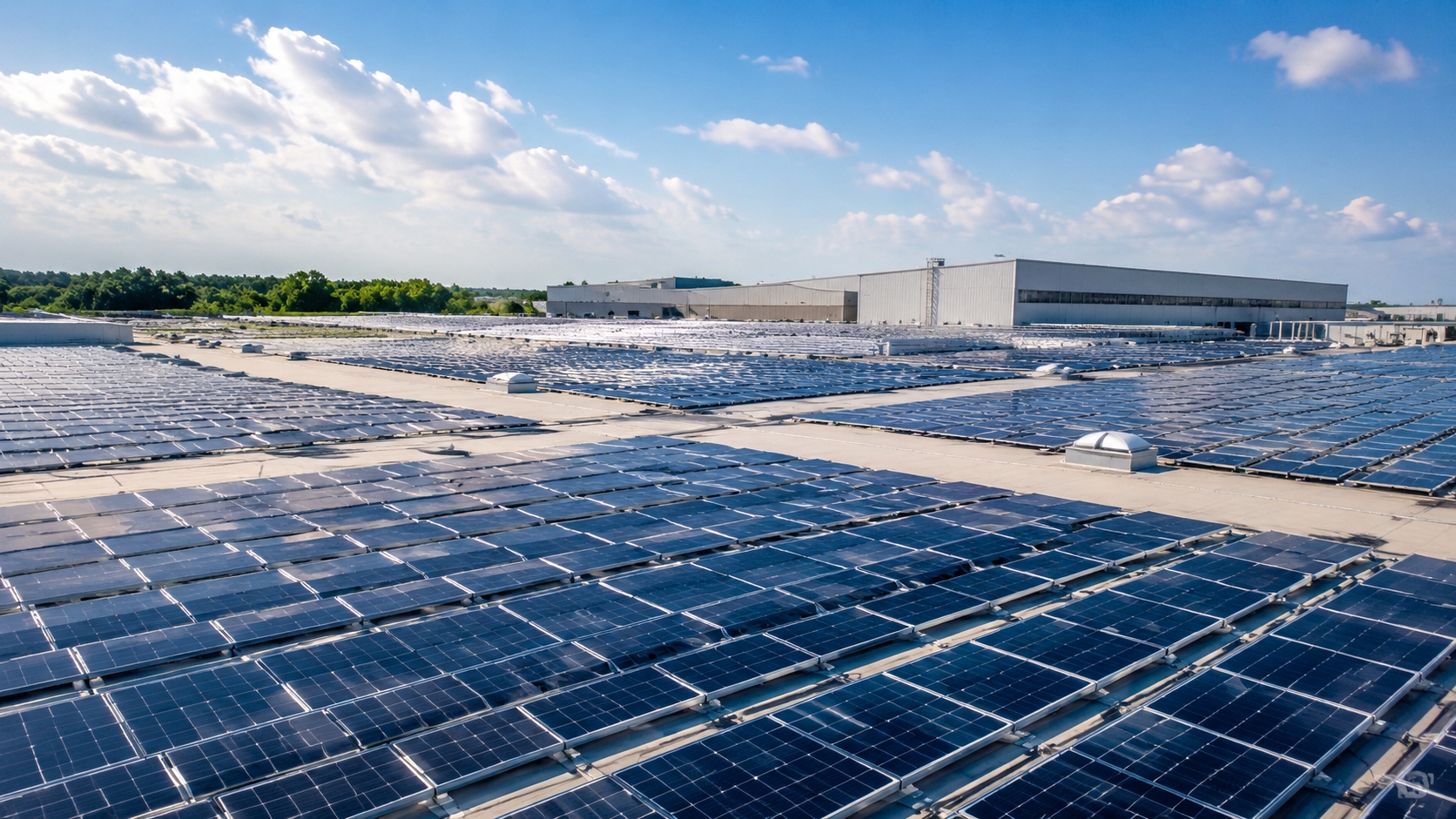
Large commercial projects include factory and warehouse rooftops, industrial campuses, parking canopies, and some large ground-mounted systems. These sites do not have the same requirements. Tongwei's module application scenarios and global project examples show how rooftop, industrial, and utility-scale applications can use different module formats and system designs.
A poor module choice usually creates one or more of these problems:
l Space problem: The project cannot fit as much DC capacity as expected.
l Electrical problem: Module voltage or current does not work well with the inverter design.
l Energy problem: A more expensive module produces little extra usable electricity.
l Supply problem: The delivered product, materials, or quality does not match what the buyer approved.
The practical way to choose is simple: first remove modules that do not meet basic project requirements. Then compare the remaining products by real layout, energy output, total installed cost, reliability, and supplier support.

Define the Site
Start with the installation site.
Before comparing module brands, collect these details:
l Available roof or land area
l Target system capacity
l Grid export limits
l Average and extreme temperatures
l Wind conditions
l Snow load
l Humidity
l Salt exposure
l Dust and sand
l Ammonia exposure
l Shading
l Roof structure
l Fixed-tilt or tracker design
These conditions can quickly remove unsuitable products.
For example, a coastal project should not be reviewed in the same way as an inland warehouse roof. IEC 61701 describes test sequences used to assess the resistance of PV modules to salt-mist corrosion.1
Agricultural sites may have ammonia exposure. IEC 62716 provides test sequences for assessing PV module resistance in wet atmospheres with high concentrations of dissolved ammonia.2
Turn each site condition into a practical question.
For a coastal site, ask whether the proposed module has relevant salt-mist test evidence.
For a hot site, compare the Pmax temperature coefficient.
For a cold site, calculate the maximum string open-circuit voltage at the design minimum module temperature.
For a farm or livestock site, check ammonia-related test evidence where exposure is relevant.
For a dusty site, review the planned cleaning method. Dry cleaning, robotic cleaning, abrasive dust, and poor-quality water can create different operating and surface risks.
One module specification should not be copied into every project. The specification should follow the real site conditions.
Separate Must-Pass Checks from Trade-Offs
Some module differences can be traded against price. Others cannot.
For example, a module with a slightly worse temperature coefficient may still make sense if it is cheaper and the project energy model shows little financial difference.
Voltage limits are different. If the cold-weather string voltage is above the permitted design limit, the string design must change. The module cannot simply receive a lower score and continue unchanged.
IEC 62548-1 covers PV array design requirements including DC wiring, protection, switching, and earthing provisions.3
Typical must-pass checks include:
l Required certificates or market approvals
l Maximum system voltage
l Cold-weather string voltage
l Inverter current limits
l Required mechanical and mounting fit
l Module dimensions or weight limits
l Important site-specific environmental requirements
After a module passes these checks, compare:
l Annual energy yield
l Total installed cost
l Temperature performance
l Degradation
l Bifacial performance
l Reliability evidence
l Supplier risk
l Warranty support
Use the exact proposed model throughout the review. Tongwei's download center, for example, separates product specifications, installation and maintenance documents, warranty documents, and white papers. These are the types of documents a project team should collect before approving a module.
Compare Space Use and Efficiency
A 650 W module is not automatically better than a 600 W module.
Module size matters.
Module | Power | Area | Power Density |
Module A | 600 W | 2.58 m² | 233 W/m² |
Module B | 650 W | 2.90 m² | 224 W/m² |
Module B has more watts per module. Module A has more watts per square meter.
The basic calculation is:
Module power ÷ module area
However, watts per square meter and module efficiency are closely related under standard test conditions. In this example, about 233 W/m² is roughly equal to 23.3% module efficiency relative to 1,000 W/m² irradiance.
Therefore, module-level W/m² should not be treated as a completely separate performance measure from efficiency.
The more useful project question is:
How much total DC capacity can actually fit in the usable project area?
The gross roof area is not the usable solar area. Skylights, fire access routes, ventilation equipment, drainage areas, shading, and structural limits reduce the space available for modules.
Module shape also matters. Two products with similar efficiency may have different lengths and widths. One may fit more rows between roof obstacles.
The EPC should build a layout with the exact module dimensions. Current Tongwei module product information provides examples of modules with different power levels and formats, which is why the exact model should be used in the layout.
A useful project-level calculation is:
Installed DC capacity ÷ usable project area
This measures the density of the real system design.
Efficiency still matters, especially on space-limited roofs. The U.S. Department of Energy explains that PV efficiency is affected by several factors, including temperature and other operating conditions.4
Suppose a higher-efficiency module costs $0.03/W more on a 50 MW project.
The extra module cost is:
50,000,000 W × $0.03/W = $1.5 million
The project must gain enough extra value to justify that $1.5 million.
Suppose the higher-efficiency module increases a rooftop design from 10 MW to 10.5 MW. Check whether the project can use the extra capacity. Look at the grid agreement, export limit, building load, inverter design, and clipping.
The question is not simply, "Which module has higher efficiency?"
The better question is:
How much extra usable energy or project value do we receive for the extra cost?
Ask What the Extra Energy Is Worth
Not every extra kilowatt-hour has the same value.
A factory may use solar power during working hours and reduce electricity bought from the grid. Extra daytime production can therefore have clear value.
A project under a power purchase agreement may receive an agreed price for electricity delivered under the contract.
An export-limited project may already reach its allowed grid export during midday.
Consider a module that increases modeled annual energy by 2%.
If most of that extra energy is produced when the factory can use it, the financial benefit may be strong.
If the extra production occurs mainly when the inverter is clipping or the grid export limit has already been reached, the financial benefit may be much smaller.
Review:
l Site electricity use
l Self-consumption rate
l Grid export limits
l Electricity prices
l Time-of-use tariffs where relevant
l PPA terms
l Inverter clipping
l Expected curtailment
Ask one simple question:
When is the extra electricity produced, and what is it worth to this project?
Check Temperature Loss and Cold-Weather Voltage
Temperature loss
Solar modules generally lose power as cell temperature rises. Higher temperatures usually cause a much larger reduction in voltage than the small increase they may cause in current.4
The important datasheet value is the Pmax temperature coefficient.
You may see values such as:
l -0.28%/°C
l -0.29%/°C
l -0.34%/°C
l -0.35%/°C
A value closer to zero means less power loss for the same temperature increase.
Consider two modules operating at a cell temperature 40°C above the 25°C reference temperature.
Module A:
-0.28% × 40 = -11.2%
Module B:
-0.35% × 40 = -14%
The difference is 2.8 percentage points at that assumed temperature.
This does not mean Module A will produce exactly 2.8% more annual energy.
Module temperature changes throughout the day and year. Irradiance, ambient temperature, wind, and mounting conditions all affect operating temperature.
Use the temperature coefficient in the project energy model. Do not turn a single hot-weather calculation into an annual energy estimate.
Cold-weather voltage
Cold weather creates a different problem. Module open-circuit voltage, or Voc, normally increases as module temperature falls.
Assume the applicable DC design limit is 1,500 V and the module has these values:
l Voc at STC: 52 V
l Voc temperature coefficient: -0.25%/°C
l Minimum module temperature used in this simplified design example: -20°C
The temperature difference from the 25°C STC reference is 45°C.
A simplified linear calculation gives:
Corrected Voc = 52 × [1 + (0.0025 × 45)]
Corrected Voc ≈ 57.85 V
For 25 modules in series:
57.85 × 25 = 1,446.25 V
For 26 modules in series:
57.85 × 26 = 1,504.10 V
In this simplified example, 25 modules remain below 1,500 V while 26 modules exceed it.
The final string length must use the exact module data, the applicable inverter and system limits, relevant tolerances, and the project's electrical design rules. IEC 62548-1 treats PV array DC design as a safety-related engineering matter.3
Do not calculate string length by simply dividing 1,500 V by the module's STC Voc.
Check Current and Inverter Fit
Modern high-power modules may operate at higher current.
Check the module's:
l Imp
l Isc
l Maximum series fuse rating
Then compare them with the inverter's:
l Maximum input current per MPPT
l Maximum short-circuit current per MPPT
l Number of strings per MPPT
l Allowed string arrangement
A module can physically connect to an inverter and still create a poor electrical design.
For example, higher module current may reduce the number of parallel strings that can be connected to one MPPT.
Bifacial modules need extra care because rear-side irradiance affects module output. IEC TS 60904-1-2 provides additional procedures for measuring the I-V characteristics of bifacial PV devices.5
Use the exact module and inverter models. Tongwei's industrial and commercial application page shows module data such as Pmax, Voc, Isc, Vmp, Imp, module dimensions, and temperature coefficients. These values need to be checked together.
Check Module Size and Installation Work
Large-format modules reduce the number of modules needed for the same DC capacity.
For a 10 MW DC system:
Using 500 W modules requires about 20,000 modules.
Using 650 W modules requires about 15,385 modules.
That is roughly 4,615 fewer modules.
Fewer modules may reduce:
l Clamps
l Module connections
l Handling actions
l Some installation steps
But larger modules can also be harder to move and install.
Check:
l Module length and width
l Module weight
l Approved lifting method
l Roof access
l Pallet movement
l Need for lifting equipment
l Wind exposure during installation
A 35 kg module on an open ground-mounted site is different from the same module being manually carried across a complex factory roof.
Do not assume that fewer modules always mean lower labor cost.
Compare modules installed per crew per shift, lifting cycles, roof staging, pallet movements, and handling damage.
If a larger module takes longer to move or needs extra equipment, part of the expected labor saving may disappear.
Check Mechanical Loads and Hail Risk
Mechanical loads
Datasheets often state front and rear mechanical load values.
The largest number does not tell the full story.
Check how the rating relates to the mounting method. The installation manual may require:
l Specific clamp zones
l Four or six clamps
l Long-side mounting
l Short-side mounting
l Specific rail or support positions
A load rating achieved in one mounting arrangement may not apply in exactly the same way to another arrangement.
IEC TS 62782 describes cyclic dynamic mechanical load testing in which a module is supported at its design support points and exposed to alternating positive and negative loads.6
The structural engineer should review the module, mounting system, roof or foundation, wind conditions, and snow requirements together.
Hail risk
Hail impact is not the same as static mechanical load.
A module with a high front-load rating is not automatically the best choice for a hail-prone site.
IEC TS 63397 provides additional testing guidance for modules used in regions with hail risk beyond the scope of the normal IEC 61215 series hail exposure.7
For a hail-prone site, review:
l Local hail history
l Module glass construction
l Available hail test evidence
l Insurer requirements
l Lender requirements where relevant
l Tracker stow strategy
l Post-storm inspection plans
A rare event can still create a large loss if thousands of modules are damaged at the same time.
Compare Degradation and Module Technology
Degradation
Degradation affects how much electricity a project produces in later years.
A performance warranty may state:
l First-year degradation
l Annual degradation after year one
l Guaranteed power after 25 or 30 years
Consider two modules.
Module A
First-year degradation: 1%
Annual degradation after year one: 0.40%
Module B
First-year degradation: 1%
Annual degradation after year one: 0.30%
The annual difference is only 0.10 percentage points, but the effect can grow over a long operating period.
For Module A, a simplified linear warranty calculation is:
100% - 1% = 99% after the first year
29 × 0.40% = 11.6%
99% - 11.6% = 87.4% at year 30
The calculation explains the warranty curve. It does not prove that the module will actually degrade at exactly that rate in the field.
IEA PVPS continues to study degradation and failure modes in newer PV cell and module technologies because field reliability depends on technology, materials, module construction, and failure mechanisms.8
For lifetime energy and financial comparisons, use the same degradation method for all shortlisted modules unless there is strong evidence for using a different assumption.
Cell technology
Commercial projects may compare PERC, TOPCon, HJT, and back-contact products.
A newer technology name does not automatically mean a better project.
Compare the exact module's:
l Efficiency
l Temperature coefficient
l Bifaciality where relevant
l Degradation evidence
l Module construction
l Production history
l Available field data
l Cost
Tongwei's high-efficiency cell page includes current cell technology information. For a project buyer, the technology name is only the starting point. The final comparison should use the data for the exact module.
Model Bifacial Gain Carefully
Bifacial modules can produce power from irradiance reaching the rear side.
Do not confuse bifaciality with bifacial gain.
Bifaciality is a module characteristic measured under defined conditions. Bifacial gain is the extra energy a real system receives from rear-side contribution.
An 80% bifaciality value does not mean the project receives 80% more annual energy.
Actual rear-side performance depends on:
l Ground reflectivity, or albedo
l Row spacing
l Module height
l Tilt
l Tracker design
l Rear shading
l Torque tubes
l Mounting rails
l Vegetation
l Snow
l Nearby surfaces
Sandia PVPMC notes that rear-side irradiance changes with array position and design and is strongly affected by ground and nearby-surface albedo.9
Ask to see the assumptions in the energy model.
For example:
l Albedo: 0.20
l Module height: 1.5 m
l Ground coverage ratio: 35%
l Bifaciality: 80%
These values can be reviewed. A statement such as "bifacial modules produce 15% more" cannot be properly judged without the site and layout assumptions behind it.
The Tongwei module portfolio includes module-specific product information, which is why the exact bifacial product data should be used instead of a general technology claim.
For an important project, test how sensitive the result is to major assumptions.
Suppose the base model uses an albedo of 0.25 and predicts 9% bifacial gain.
Compare reasonable cases such as:
l Lower case: albedo 0.15
l Base case: albedo 0.25
l Higher case: albedo 0.35
The actual values should come from the site or reasonable engineering assumptions.
If an expensive module only wins when the model uses optimistic rear-side assumptions, the buyer should see that risk before placing the order.
Check Key Module Parts
Buyers do not need to become materials engineers. The goal is to know which important parts are being supplied and whether the reviewed product matches the delivered product.
Glass
Commercial modules may use glass-backsheet or glass-glass construction.
Check:
l Front glass thickness
l Rear glass thickness where applicable
l Glass type stated by the manufacturer
l Frame design
l Module weight
l Transport and handling instructions
Glass thickness should be reviewed together with module size, structural design, mounting, transport, and handling.
For large modules, define inspection rules for broken glass and edge damage.
Encapsulant
The encapsulant surrounds the cells inside the module laminate. Common material systems include EVA and POE-based products.
Do not assume that one material name is always better.
Ask what material structure is used and what test evidence applies to that module design.
Potential-induced degradation, or PID, is also important in high-voltage PV systems. IEC TS 62804-1 provides procedures for assessing crystalline-silicon PV module sensitivity to PID under high-voltage stress.10
Check:
l Encapsulant structure
l Material used on each side of the cells
l The tested BOM
l Available PID test evidence
Junction box and cables
The junction box contains electrical connections and bypass diodes.
Check:
l Junction box identification
l IP rating
l Diode design
l Cable length
l Cable cross-section
l Relevant thermal information
Cable length can affect installation. A cable that is too short may lead to poor routing or excessive tension.
Where practical, place a sample module on the intended mounting or tracker system before mass delivery. This can show cable-routing and connector-position problems that are difficult to see on a datasheet.
Connectors
Two connectors should not be treated as an approved pair simply because they look similar.
Identify the connector manufacturer and model used on the proposed module.
Review:
l Approved mating arrangement
l Crimping method
l Cable routing
l Connector position
l Water exposure
l Cable tension
Record the connector information in the approved BOM and confirm it before mass shipment.
Control the BOM
BOM means bill of materials.
A module BOM may include:
l Cells
l Glass
l Encapsulants
l Backsheets
l Frames
l Junction boxes
l Cables
l Connectors
IEC 62941 covers quality systems for PV module manufacturing and includes the selection and control of materials and manufacturing processes.11
Consider a simple example.
The project approves a module built with a specific encapsulant and connector combination. During mass production, an important component changes.
The wattage, Voc, and dimensions on the commercial datasheet may look almost the same. The delivered module construction, however, is no longer identical to the construction reviewed by the project.
The supply agreement should state:
l Which materials or component combinations are approved
l Which changes require notice
l Which changes require buyer approval
l When additional review or testing is required
IEC TS 62915 provides a structured approach to retesting modified PV module designs and maintaining type approval and qualification after changes.12
The principle is simple:
The product approved should be the product delivered.
The Tongwei technical download center provides product, installation, warranty, and white-paper documents. For any supplier, use the latest documents for the exact product being offered.
Check Certificates and Match Tests to the Site
Ask for certificates that cover the proposed module model or model family.
IEC 61215-1 covers design qualification and type approval for terrestrial PV modules. The standard clearly states that qualification test results are not a quantitative prediction of module lifetime.13
IEC 61730-1 covers basic module construction requirements for safe electrical and mechanical operation. IEC 61730-2 covers safety testing requirements.14
Check:
l Exact model designation or covered model family
l Certificate holder
l Certificate status
l Relevant qualification scope
l Testing or certification organization
Do not accept a certificate only because it carries the same brand name.
Certification, extended reliability testing, and production quality records answer different questions:
l Certification: Does the product meet the relevant qualification or safety requirements?
l Additional reliability testing: How did the module behave under extra stress tests?
l Production quality records: Is the factory consistently making the approved product?
Hot and humid sites
Review damp heat, humidity freeze, and relevant PID evidence.
Coastal sites
Review salt-mist corrosion evidence. IEC 61701 specifically covers salt-mist corrosion testing for PV modules.1
Agricultural sites
Review ammonia corrosion evidence where exposure is relevant. IEC 62716 covers PV module ammonia corrosion testing.2
Desert sites
Review:
l Dust and sand exposure
l High-temperature performance
l Cleaning method
l Abrasion or surface risks from frequent cleaning
High-wind or snow sites
Review mechanical load, support positions, and clamp configuration. Dynamic mechanical load evidence may also be relevant.6
Hail-prone sites
Review increased hail-resistance test evidence, glass construction, insurer requirements, and tracker operating strategy where relevant.7
Ask for tests because they address a real project risk. A longer list of test names does not automatically mean a better module specification.
Tongwei's module reliability page is one example of how a manufacturer presents reliability and environmental-condition information. The project should still check the exact model and the evidence required by its own contract.
Look Beyond a Simple Pass Result
A test report may simply state that a module passed.
For a large project, detailed results can provide more information.
Depending on the test, review:
l Power change before and after testing
l Visual defects
l EL changes
l Insulation results
l Other test-specific findings
IEC TR 63279 reviews sequential and combined accelerated stress testing because some field degradation modes may not be shown by single-factor or steady-state tests alone.15
The goal is not to collect as many reports as possible.
Ask:
l Did one shortlisted module show more degradation?
l Did EL images change after testing?
l Does the tested construction match the proposed BOM?
l Are the observed weaknesses relevant to the project site?
A report is useful when it changes the buying decision, contract terms, or inspection plan.
Know Who Checks Each Risk
One person should not be expected to review every part of a large solar module purchase.
Team | Main Checks |
Project owner or buyer | Commercial needs, supplier risk, warranty, final purchase decision |
EPC or electrical engineer | Voc, string length, current, MPPTs, inverter fit, electrical layout |
Structural engineer | Roof or foundation loads, mounting, wind and snow conditions |
Energy modeler or EPC | Annual yield, temperature losses, bifacial assumptions, clipping |
Technical adviser or QA team | BOM, factory review, test evidence, production and shipment inspection |
A procurement manager does not need to personally calculate cold-weather string voltage. The buying process should confirm that the right engineer has checked it.
Review the Factory and Traceability
Factory control
Ask which factory will produce the order.
Review:
l Incoming material inspection
l Cell sorting
l String inspection
l Lamination control
l EL inspection
l Electrical performance testing
l Final visual inspection
l Serial-number traceability
For a large order, a factory audit may be useful.
A clean factory floor is not enough. The important question is whether the factory can repeatedly make the approved module.
Ask:
l Is this the factory producing the project order?
l How are approved BOM materials identified?
l How are incoming materials checked?
l How are process problems recorded?
l How are rejected modules separated?
l Can serial numbers be linked to production data?
l Who approves material or process changes?
IEC 62941 focuses on manufacturing quality systems and control of materials and processes used to make qualified PV modules.11
Traceability
For a large project, require unique module identification and useful serial-number traceability.
Depending on the factory system, a serial number may be linked to:
l Manufacturing date
l Production line
l Factory
l Electrical test results
l Important component or material batches
Suppose 300 modules develop a similar junction box problem.
Can the supplier identify other modules linked to the same component batch or production period?
Without good traceability, the project may need to inspect a much larger number of modules.
Ask the supplier to show what information can be retrieved from a sample serial number.
Inspect Before Shipping
For a large order, define the inspection plan before production or shipment decisions depend on it.
Inspection may include:
l Visual checks
l Dimension checks
l Label checks
l Packaging checks
l EL inspection
l Flash-data review
l Sample laboratory testing
Set the sample size, defect categories, and acceptance limits in advance.
If excessive cell damage is found in a sample, agreed actions may include:
l Increasing the sample size
l Expanding inspection of the batch
l Rejecting an affected batch under the contract rules
l Requiring corrective action
Sampling does not prove that every module is defect-free. It helps find unusual defect rates and gives the project a clear reason to expand the investigation.
Review flash data
Manufacturers commonly measure module electrical performance during production. IEC 60904-1 describes procedures for measuring PV device current-voltage, or I-V, characteristics under natural or simulated sunlight.16
For a large project, production flash data may be provided.
Suppose the order specifies 620 W modules.
Check:
l Minimum delivered power
l Average delivered power
l Power binning rules
l Measurement tolerance
l Current distribution
l Voltage distribution
For a large dataset, look for unusual outliers, shifts between production batches, and results that do not match the agreed power bins.
A simple process is:
Collect the data → check the distribution → find unusual results → investigate the relevant production group.
Use EL inspection
Electroluminescence, or EL, imaging can show cell and interconnection features that are difficult to see during normal visual inspection.
IEC TS 60904-13 covers methods for capturing and processing module EL images and gives guidance for interpreting visible image features.17
EL images may show:
l Cell cracks
l Broken or electrically inactive cell areas
l Inactive regions
l Some interconnection-related features
Not every visible line means a module must be rejected.
Define defect categories and acceptance rules before inspection decisions are made.
The process should be:
Find the feature → classify it → compare it with the agreed limit → accept the module or expand the inspection.
Plan Transport and Site Storage
Large modules need careful transport and handling.
IEC 62759-1 describes methods for simulating transportation of complete PV module package units and subsequent environmental impacts.18
Review:
l Modules per pallet
l Pallet dimensions
l Pallet weight
l Container loading
l Stacking limits
l Storage orientation
Also check the project site.
Can the truck reach the unloading area?
Can the forklift handle the pallet?
Can the roof lifting plan handle the pallet dimensions and weight?
When the shipment arrives, record damaged cartons, tilted pallets, broken straps, water damage, and impact marks.
Take photographs and keep relevant packaging evidence if a transport claim may be needed.
Transport risk does not end at unloading.
Modules may remain in temporary storage for days or weeks.
Check:
l Ground conditions
l Rain and water exposure
l Pallet stability
l Stacking restrictions
l Outdoor storage instructions
l Movement from storage to the installation area
The logistics plan should cover the full route from factory packaging to final installation.
Compare the Full System Cost
Module price per watt is only one part of project cost.
A higher-power module may reduce the number of modules and affect:
l Clamps
l Rails
l Trackers
l Cables
l Connectors
l Labor
l Transport
A larger module may also need different mounting, lifting, or electrical arrangements.
Ask the EPC to prepare a bill of quantities for each shortlisted module.
For example:
Module A
Module price: $0.105/W
Installed project cost: $0.68/W
Module B
Module price: $0.110/W
Installed project cost: $0.665/W
Module B costs more at the module level but produces a cheaper installed system in this example.
A module-price comparison alone would give the wrong answer.
For a long-term comparison, also consider:
l Lifetime energy production
l Levelized cost of energy, or LCOE
l Net present value, or NPV
l Other financial measures used by the project
The lowest installed $/W and the lowest long-term project cost are not always the same choice.
Model Energy and Check Clipping
Use the exact module in the energy model
Do not simply change the wattage from one module to another.
The annual energy comparison should include relevant differences in:
l Module performance data
l Temperature behavior
l Electrical characteristics
l Bifacial assumptions
l Array layout
Compare annual energy and specific yield.
Specific yield = kWh generated per installed kWp
Use the same weather data and basic loss method for all shortlisted modules unless a real module difference requires another assumption.
For lifetime analysis, use a consistent degradation method.
Run sensitivity checks on important assumptions such as:
l Bifacial gain
l Albedo
l Degradation
l Soiling
l Clipping
l Export limits
Check clipping
A project may install more DC module capacity than inverter AC capacity.
For example:
DC capacity: 13 MW
AC capacity: 10 MW
DC/AC ratio = 1.30
NREL describes the DC-to-AC ratio, also called inverter loading ratio, as the relationship between DC array capacity and inverter AC rating. Its research also explains that inverter clipping occurs when available DC power is above the inverter's conversion capacity.19
A higher DC/AC ratio can improve inverter use outside the strongest sunlight periods, but it may also increase clipping.
Ask:
l How much annual energy is clipped?
l Does the module change the preferred DC/AC ratio?
l Would more inverter capacity be worth the cost?
Clipping is not the same as an export limit.
Inverter clipping happens when available DC power is above the inverter's conversion capacity.
Export limitation or curtailment happens when the site, grid, contract, or operating rules limit how much electricity can be delivered.
Both can reduce the value of extra module energy, but they are different problems.
Read the Warranty and Review the Supplier
Warranty
Read the warranty document, not only the product brochure.
Separate:
l Product warranty
l Performance warranty
Then ask what happens when a claim is made.
Who tests the module?
Who pays for testing?
Who pays for shipping?
Who removes the failed module?
Who installs the replacement?
Does the supplier provide a replacement module or financial compensation?
How is compensation calculated?
What happens if the original model is no longer sold?
A "30-year warranty" may still leave the owner with labor, access, testing, or shipping costs, depending on the contract.
Also check:
l Notice deadlines
l Required monitoring records
l Serial-number requirements
l Evidence needed for a claim
l Testing procedures
l Dispute procedures
l Local claim contact
Tongwei's download center includes a warranty document category. Use the same approach with any supplier: collect and read the actual warranty before procurement.
Supplier
A technically suitable module can still create a commercial problem if the supplier cannot deliver or support the project.
Review:
l Financial condition
l Manufacturing history
l Production capacity
l Factory locations
l Warranty process
l Local technical support
l Local claim support
l Relevant project references
Look for references from similar projects.
A mild-climate rooftop is not the same as a large ground-mounted project in a desert climate.
Tongwei's global projects page, for example, separates utility-scale, industrial and commercial, and residential project references. When checking any supplier, look for experience that is relevant to your own site.
Separate supplier risk into four simple questions:
l Delivery: Can the supplier make and deliver the required quantity on time?
l Quality: Can the factory repeatedly make the approved module and BOM?
l Long-term support: Is the supplier likely to be able to handle future obligations?
l Claims: Is there a clear process when a technical or warranty problem occurs?
Large production capacity alone does not answer all four questions.
Plan Spare Modules
The exact module model may no longer be sold ten years later.
Future replacement modules may have different dimensions or electrical values.
Consider:
l Project size
l Expected installation or operating breakage
l Warranty replacement lead time
l Future model availability
l Storage cost
The same wattage does not mean two modules are interchangeable.
A future 620 W module may have different:
l Dimensions
l Mounting points
l Voc
l Vmp
l Imp
l Connector type
l Appearance where this matters
If spare modules are purchased, store them correctly and track serial numbers and storage locations.
Use a Pass/Fail Screen and a Scorecard
Complete the must-pass checks first.
Requirement | Decision |
Required certification | Pass / Fail |
Cold-weather voltage compatibility | Pass / Fail |
Inverter current compatibility | Pass / Fail |
Required mechanical and mounting compatibility | Pass / Fail |
Important environmental requirements | Pass / Fail |
If a module fails an important requirement, change the system design or remove the module from the shortlist.
For modules that pass, a weighted scorecard can be used.
Item | Weight |
Energy yield | 20% |
Reliability | 20% |
Installed cost | 15% |
Supplier risk | 15% |
Electrical design flexibility | 10% |
Layout and mounting suitability | 10% |
Warranty | 5% |
Quality control | 5% |
A simple score can be:
5 = Excellent
4 = Good
3 = Acceptable
2 = Weak
1 = Poor
Set the scoring rules before supplier prices influence the technical review.
Also record why a score was given.
Do not write only:
Reliability = 5.
Record the evidence, such as test results, BOM controls, project references, or factory quality records.
See How the Comparison Works in a Real Project
Consider a 12 MW warehouse rooftop comparing two modules.
Module A
l 620 W
l Smaller module area
l Higher module-level power density
l Lower operating current
l Slightly lower purchase price
Module B
l 650 W
l Larger module dimensions
l Slightly better Pmax temperature coefficient
l Higher operating current
l Higher purchase price
A buyer looking only at wattage may choose Module B.
Roof layout
The EPC uses the exact module dimensions and models skylights, fire routes, and narrow roof sections.
l Module A design: 12.0 MW DC
l Module B design: 11.8 MW DC
Module A fits more total DC capacity on this roof even though each individual module has lower wattage.
Electrical design
Module A fits the planned strings-per-MPPT arrangement.
Module B can still be used, but its higher current requires a design change. The project includes the cost of that change in the comparison.
Energy and electricity value
Module B produces slightly more modeled energy per installed kWp because of its assumed performance characteristics.
Module A has more total installed DC capacity.
The warehouse also has high daytime electricity use, so much of Module A's extra total production can be used on site.
Installed cost and supply risk
Module B uses fewer modules, but electrical changes and larger-module handling reduce part of the expected saving.
Both modules pass the required certificate checks. The buyer then compares BOM control, test evidence, traceability, inspection terms, and warranty support.
Decision
Module A may win this project because it gives a better combination of roof use, electrical fit, usable energy, installed cost, and supply risk.
This does not mean every 620 W module is better than every 650 W module.
On an open ground-mounted site with compatible inverters and no space limit, Module B may produce the better system result.
The project design decides which module is better.
Ask Suppliers These Questions
The following questions can be used in an RFQ or technical review:
1. What exact module model will be delivered?
2. Which factory will produce the order?
3. What cell technology does the exact module use?
4. What are the module dimensions and weight?
5. What is the Pmax temperature coefficient?
6. What is the first-year degradation allowance?
7. What is the annual degradation allowance after year one?
8. What is the stated bifaciality, where applicable?
9. What glass construction is used?
10. What encapsulant structure is used?
11. Which connector manufacturer and model are used?
12. Which important BOM parts may change during the order?
13. How are important BOM changes reported and approved?
14. Which certificates cover the proposed module?
15. What reliability test evidence is relevant to the project site?
16. Can production flash data be provided?
17. Which EL inspection records are available?
18. What information can be traced from a module serial number?
19. What are the main warranty exclusions and claim requirements?
20. How are local technical and warranty claims handled?
A supplier should answer relevant questions with clear product information and supporting documents.
Terms such as "Tier 1," "premium quality," and "bankable product" do not replace model-specific technical evidence.
Make the Final Choice
Remove modules that fail the site's basic environmental, electrical, mechanical, or certification requirements.
Use the exact module dimensions to compare real layouts.
Model usable annual energy with the same basic assumptions.
Compare the full installed system cost, not only module $/W.
Then review the BOM, reliability evidence, factory controls, traceability, supplier support, and warranty.
The best solar module is not automatically the module with the highest wattage or highest efficiency.
It is the module that gives the project the best balance of usable energy, total cost, technical fit, reliability, and long-term supply risk.