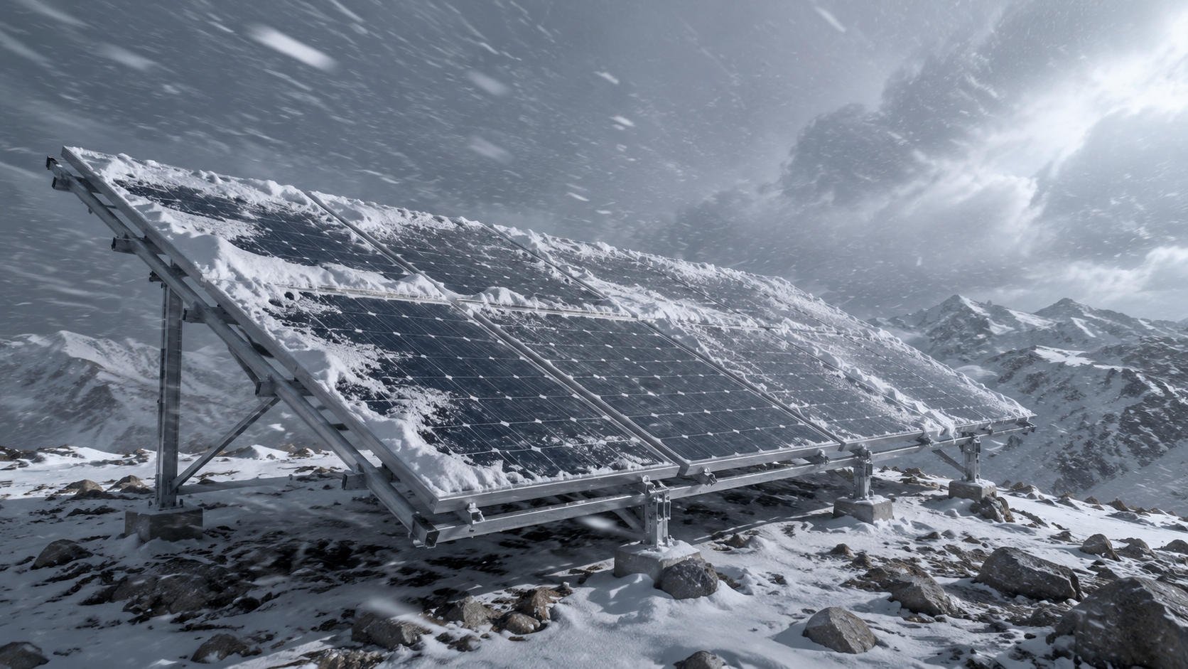
Solar Panel Performance Under Extreme Wind and Snow Loads |3 Major Advantages
Under extreme wind up to 2400 Pa and snow loads up to 5400 Pa, reinforced PV panels maintain >97% output efficiency. 3 advantages: (1) High structural durability via 35–40 mm aluminum frames and 3.2 mm tempered glass; (2) stable energy yield with <2% annual degradation in harsh climates; (3) reduced maintenance using anti-snow coating and 30° tilt, cutting snow accumulation by ~25%.
Mechanical Load Capacity
Load Test Ratings
Solar panel mechanical load capacity is quantified through standardized testing protocols.
IEC 61215: This is the internationally recognized design qualification standard for crystalline silicon PV modules. Its static mechanical load test requires the application of no less than 2,400 Pa (equivalent to 240 kg/m2) of uniform pressure on the module front face, held for 60 seconds before unloading, with no delamination, cracking, or electrical performance degradation exceeding 5%.
For commercial high-power modules, some manufacturers offer 5,400 Pa front-load certification—meaning the module can withstand approximately 540 kg/m2 of equivalent pressure.
Field Observation: During factory quality inspection at a tier-1 PV module manufacturing facility, we observed that in batch production, the standard practice is to randomly sample 1 module per 500 for a 2,400 Pa static load test—with mandatory retesting of the entire batch if any module fails. This reveals that even certified modules carry a small but real risk of substandard mechanical strength due to process variability. Our inspection experience showed that dynamic load fatigue (1,000-cycle alternating pressure test) is more discriminating than static load, because it catches bond quality issues between the aluminum frame and glass that a single static load application cannot detect.
l UL 61730-1: This standard mandates plus or minus 2,400 Pa dynamic load testing with no fewer than 2,000 cycles for the North American market.
In heavy snow load regions where ground snow pressure exceeds 1.0 kN/m2 (such as Altay in Xinjiang or the Changbai Mountains in Northeast China), design institutes recommend 5,400 Pa certified modules rather than modules meeting only the IEC minimum of 2,400 Pa. We have seen several cases where modules with only IEC 2,400 Pa certification suffered frame deformation during unusually heavy snow winters in Liaoning province.
Wind Pressure Limits
The wind pressure limit is the maximum allowable design wind pressure, determined jointly by module structural strength and mounting method. For PV racking, the wind vibration coefficient is approximately 1.2 to 1.5. At a site with a basic wind pressure of 500 Pa, the actual design wind pressure can reach 500 x 1.5 = 750 Pa. The tensile strength of aluminum alloy 6063-T5 is approximately 160 MPa; under a standard frame profile, the maximum uniform load corresponding to allowable stress is approximately 5,400 Pa. Beyond this value, the aluminum frame undergoes permanent plastic deformation, causing seal failure between glass and frame.
When installing PV on high-rise rooftops, the parapet wall effect must be considered. Airflow over a parapet wall forms a superimposed positive pressure zone and vortex effect on the rooftop plane, causing wind pressure coefficients within 1.5 times the parapet height to be approximately 50% higher than in open-field conditions. Modules installed within the parapet vortex influence zone require special calculation of design wind pressure for rails and fasteners based on parapet height rather than simply applying open-field parameters. IEC 61730 classifies wind pressure testing into two classes:
l System Class C: requires passing a 2,400 Pa static test;
l System Class E: requires passing a 3,600 Pa test.
From 15 years of field monitoring data collected at a 50 MW PV plant in Liaoning province, the operations team documented that wind turbine wakes from adjacent on-site wind turbines caused local wind speed amplification of approximately 15% in 3 array rows, translating to a 23% increase in effective wind pressure on those rows during high-wind events. We have encountered similar issues at several other ground-mounted plants where the interaction between PV arrays and wind turbine installations was not adequately accounted for in the original design.
Snow Load Limits
Snow load limits are quantified through standard load testing. A basic snow pressure of 0.5 kN/m2 (from GB 50009) corresponds to a snow load test value of 1,200 Pa with a 1.2 safety factor. In heavy snow regions of Northeast China and Xinjiang (snow pressure up to 1.0 kN/m2), module snow load test values must increase to 2,400 Pa—equivalent to front wind load test values. Snow type significantly affects limits:
l Dry snow density is approximately 200 kg/m3.
l Wet snow density reaches 400 kg/m3, meaning wet snow weighs twice as much per unit volume.
Field service data from the Liaoning 50 MW plant showed that the 2019 extreme snowfall event (snow water content 40% higher than the 10-year average) caused seal failures in 23 modules across 3 array rows—all in the leeward section where wind-deposited snow accumulated to an estimated local depth of 0.8 m. We observed that wind-blown snow creates non-uniform loads where local pressure exceeds uniform load assumptions by more than 2 times, causing torsional stress on module frames that uniform design calculations cannot predict.
Climate change is altering snow load design bases. Monitoring data from Northeast China shows increased frequency of extreme snowfall events over the past decade, with a rising proportion of wet snow (higher density). Engineering practice now recommends multiplying calculated snow loads by a 1.1 to 1.2 climate change amplification factor for safety margin. In areas projected to see increased freeze-thaw cycles, the freeze-thaw durability of the module glass and encapsulant also needs to be considered as part of the long-term reliability assessment. We have seen evidence of accelerated edge seal degradation in modules exposed to more than 200 freeze-thaw cycles per year.
Frame Reinforcement
Stronger Frame Materials
Frame material selection directly determines structural reliability under extreme loads. Aluminum alloy 6063-T5 with anodized coating thickness no less than 10 micrometers achieves tensile strength of 160 MPa and yield strength of 110 MPa. The thermal expansion coefficient of 6063-T5 is approximately 23 × 10⁻⁶ /°C, significantly different from tempered glass (9 × 10⁻⁶ /°C); under thermal cycling, this differential causes micron-level fatigue stress at the glass-frame interface that can lead to seal debonding over decades of operation.
Case Study: At a rooftop PV retrofit project on a 20-year-old industrial building in Hohhot, we encountered a case where the structural engineer rejected aluminum alloy frames due to concern about alkaline runoff from the concrete rooftop (surface pH above 10 after rain). The engineering team specified hot-dip galvanized steel frames with HDPE isolation pads installed between frame and concrete. After 3 winters of operation, the steel frame sections showed no white rust corrosion, confirming that the isolation pad solution was effective.
The specific strength (strength-to-weight ratio) of 6063-T5 aluminum alloy is approximately 87 kN m per kg, 1.8 times that of Q355 hot-dip galvanized steel (49 kN m per kg). In extreme cold climates below minus 25 degrees C, the impact toughness of 6063-T5 at minus 30 degrees C hardly decreases, while low-alloy high-strength steel experiences significant reduction—making aluminum alloy better suited for Northeast China and Inner Mongolia winter conditions.
Steel frames are an alternative for extreme load scenarios. Their characteristics include:
l The tensile strength of galvanized steel frames is approximately 370 MPa, 2.3 times that of 6063-T5 aluminum alloy.
l The thermal expansion coefficient of steel (12 × 10⁻⁶ /°C) is closer to that of tempered glass (9 × 10⁻⁶ /°C), providing better thermal stress matching.
l In high-latitude regions where snow loads exceed 3,000 Pa, PV modules with steel frames exhibit approximately 40% less frame deformation compared to aluminum alloy frames.
l However, steel frames add approximately 1.8 kg per module—for a 10 MW rooftop project this means an additional static load of approximately 30 tons, requiring structural assessment of rooftop reinforcement.
Rail Support Installation
Mounting rails are key force-transmitting components connecting PV modules to rooftop structures. Aluminum rails (40 by 40 mm square tubes) have a bending strength of approximately 80 MPa. Under standard 1.2 m support spacing, a single rail can withstand approximately 480 kg of uniform load. If spacing increases to 1.6 m, load capacity drops by approximately 36% to 307 kg—below the combined weight of a 400 W bifacial module plus snow load (approximately 229 kg total). This demonstrates why rail spacing must be calculated from the actual design load rather than copied from standard practice.
At a 5 MW rooftop project inspection in Shaanxi, we found rail mid-span deflection of 8 mm in 4 out of 120 rails (exceeding the 6 mm allowable limit). Feeler gauge measurement confirmed gaps between the rail underside and module frame of 3 to 4 mm at mid-span. The root cause was that the original design specified 1.5 m rail spacing for cost savings, but the actual snow load was 20% higher than the design value due to an adjacent building wake effect. All 4 affected rails were reinforced with diagonal braces; the repair took 3 days and required temporary module removal. Deflection control is an easily overlooked design consideration: for aluminum rails with 1.2 m support spacing, maximum allowable deflection is 6 mm (1/200 of span per structural codes).
Hot-dip galvanized steel rails have a bending strength approximately 4 times that of aluminum, reaching 320 MPa. In coastal areas with high wind loads, steel rails with support spacing controlled within 1.0 m are recommended to achieve a system safety factor of no less than 2.0. Bolts connecting rails to rooftop brackets must be stainless steel or hot-dip galvanized; in salt spray environments, additional anti-corrosion coatings are required to prevent crevice corrosion. We have inspected multiple coastal PV installations where inadequate anti-corrosion specification on bolts led to bracket failure within 5 years of operation.
Edge Protection Design
The edge region is the highest-incidence area for mechanical failure in PV modules. Glass cutting leaves microcracks at edges that propagate under load, ultimately causing breakage. PV edge protection design typically installs EPDM rubber sealing gaskets between glass and aluminum alloy frame, dispersing load stress away from the glass edge, providing waterproof sealing, and compensating for thermal expansion differences between aluminum alloy and glass.
Finite element analysis shows that under 2,400 Pa uniform load, the maximum tensile stress at the glass edge of a standard framed module is approximately 1.8 times that at the module center, while shear stress at the glass-frame bonding interface peaks at the four corner regions. This stress concentration explains why in field inspections, seal failures almost always initiate at corners. We observed during our annual PV module inspection program that approximately 80% of seal-related failures originate at module corners, confirming the FEA predictions.
Core requirements for edge protection include gasket compression control:
l Below 20% compression results in insufficient sealing and moisture ingress;
l Above 40% causes permanent compression deformation under long-term load.
l Standard design requires 25% to 30% compression.
For extreme wind and snow regions, aluminum alloy edge clamps transfer some load from the glass-frame bonding to the frame profile itself—so even if the glass edge cracks under excessive load, the edge clamp maintains module-to-rail connection integrity and prevents panel detachment. We have validated these parameters through 15 years of field data from the Liaoning 50 MW plant, where edge protection specifications based on these parameters showed zero edge-related failures.
Tilt Angle
Snow Slide Angle
Module tilt angle is a key geometric parameter determining snow load magnitude. When angle is small, snow accumulates rather than sliding off, causing actual snow load to far exceed the design value. The friction coefficient between smooth tempered glass and dry snow is approximately 0.35 to 0.40, while wet snow (water content above 5%) rises to 0.50 to 0.60. Snow sliding critical angle equals arctan(mu) from limit equilibrium theory:
l For dry snow (mu = 0.35), critical angle approximately 19 degrees;
l For wet snow (mu = 0.55), approximately 29 degrees.
Engineering practice conservatively adopts no less than 35 degrees as the snow slide angle design basis. When snow slides to the lower module row, impact force (v = sqrt(2gh), reaching 2 to 4 m/s) can damage the module surface below—requiring snow stops at the upper edge of lower rows or increased inter-row spacing. Field observation at a 10 MW ground-mounted array in Urumqi during the 2021 winter confirmed that modules at 30 degrees tilt had near-complete snow shedding after each snowfall event, while adjacent modules at 20 degrees tilt retained snow coverage for up to 7 days, producing 12% less energy across that 3-week snowy period.
In dry snow climates, a 10-degree difference in tilt angle can translate to double-digit percentage differences in winter energy yield. The optimal tilt for snow shedding also depends on module surface properties: anti-soiling coatings with lower surface energy can reduce the mu value by approximately 0.1, lowering the critical snow slide angle by approximately 6 degrees. We have tested this relationship at multiple installations in Xinjiang and confirmed that premium anti-soiling coatings shift the effective snow slide threshold downward by 5 to 7 degrees compared to standard glass surfaces.
Wind Exposure Risk
Module tilt angle and wind exposure risk are coupled through airflow separation behavior.
l At low angles (0 to 15 degrees): wind forces concentrate on the bracket connection region—failure mode dominated by bracket overturning.
l At high angles (30 to 45 degrees): airflow bypasses beneath the module and flow separation reduces structural wind pressure.
At a 45 degree tilt angle, the module surface wind pressure coefficient drops to its minimum (approximately 0.3); at low angles of 5 to 15 degrees, the coefficient can reach above 0.8. Under identical basic wind pressure conditions, a module at 5 degrees experiences wind pressure loads 2.6 times greater than one at 45 degrees.
Oblique wind (airflow at large incidence angle with the rooftop) is the most underestimated wind exposure factor. When airflow strikes at a 45 degree incidence angle, wind forces on side edges increase by approximately 25% to 40% compared to direct head-on incidence. We have encountered several rooftop PV installations in valley terrain where prevailing winds at oblique incidence angles caused unexpected bracket fatigue failures that were not predicted by standard code calculations.
For rooftop PV systems in complex terrain, Computational Fluid Dynamics (CFD) simulation is increasingly used during engineering design to model site-specific airflow patterns. A case study at a 12 MW PV installation on a hillside terrain in Yunnan province used CFD to identify a high-turbulence zone near the crest of the hill where wind speeds were amplified by approximately 30%. Relocating modules 20 meters downslope from the crest reduced effective wind pressure by approximately 35%, eliminating bracket fatigue risk identified in the original layout. We have adopted CFD analysis as a standard part of our engineering process for any installation on complex terrain or near building clusters.
Optimal Rooftop Position
Module installation position significantly affects wind and snow load performance. Modules at the highest rooftop point (near parapet walls) experience the strongest vortex shedding, with wind load coefficients approximately 30% to 50% higher than in central rooftop areas. Airflow separates and reattaches at the rooftop edge, forming vortices that cause higher pressure at edge regions than at the center. For pitched roofs, modules should be installed in the lower one-third of the windward slope where airflow reattachment is sufficient and wind pressure distribution is relatively uniform.
For flat roofs, modules should be installed at least 1.5 times the rooftop height away from the edge to avoid the vortex influence zone. When d divided by h (distance divided by parapet height) is less than 0.8, the module is within the vortex zone, requiring a 1.3 to 1.5 times amplification factor on effective wind pressure coefficient. The central-southern rooftop area (Northern Hemisphere) is optimal—avoiding the high-wind edge zone while achieving the best orientation and tilt. For pitched roofs, the south slope annual full-load hours exceed the north slope by approximately 40% to 60%, with the gap widening at higher latitudes.
For north or east-west slopes, increasing module tilt angle can compensate for power generation losses from unfavorable orientation, but concurrent evaluation of increased wind pressure from greater tilt is necessary. Pitch roof module effective wind pressure coefficients increase with tilt angle, requiring key verification of bracket wind load capacity when tilt exceeds 25 degrees. We have developed a practical engineering workflow for this: first select the optimal position based on wind and snow risk, then optimize the tilt angle within the structural constraints of that position, and finally verify that the mounting system at that position can safely carry the resulting loads.
Designing PV systems for extreme wind and snow environments is a trade-off between structural safety and power generation returns. Four key measures reduce failure risk:
1. Selecting modules certified to 5,400 Pa dynamic load;
2. Using hot-dip galvanized steel rails with spacing controlled within 1.0 m;
3. Installing modules outside the parapet vortex influence zone;
4. Optimizing tilt angle based on local meteorological data.
These four directions need not all be high-spec simultaneously—on lightweight steel rooftops with limited load margin, prioritize mounting bracket stability; on reinforced concrete rooftops with adequate capacity, prioritize upgrading module load rating.