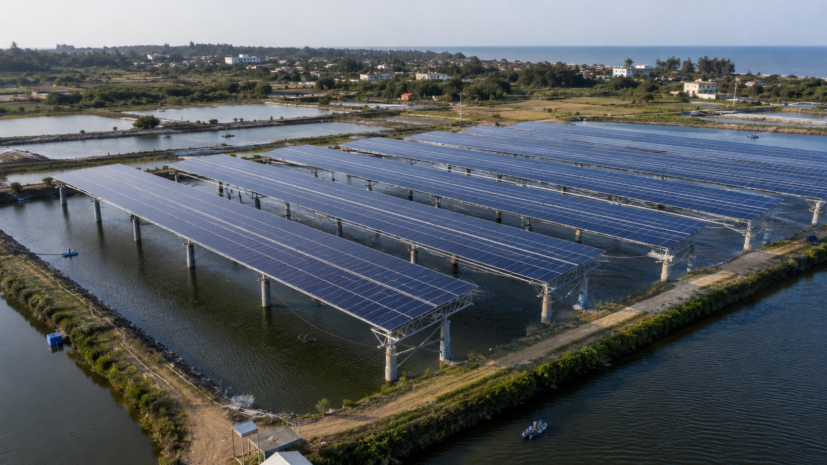
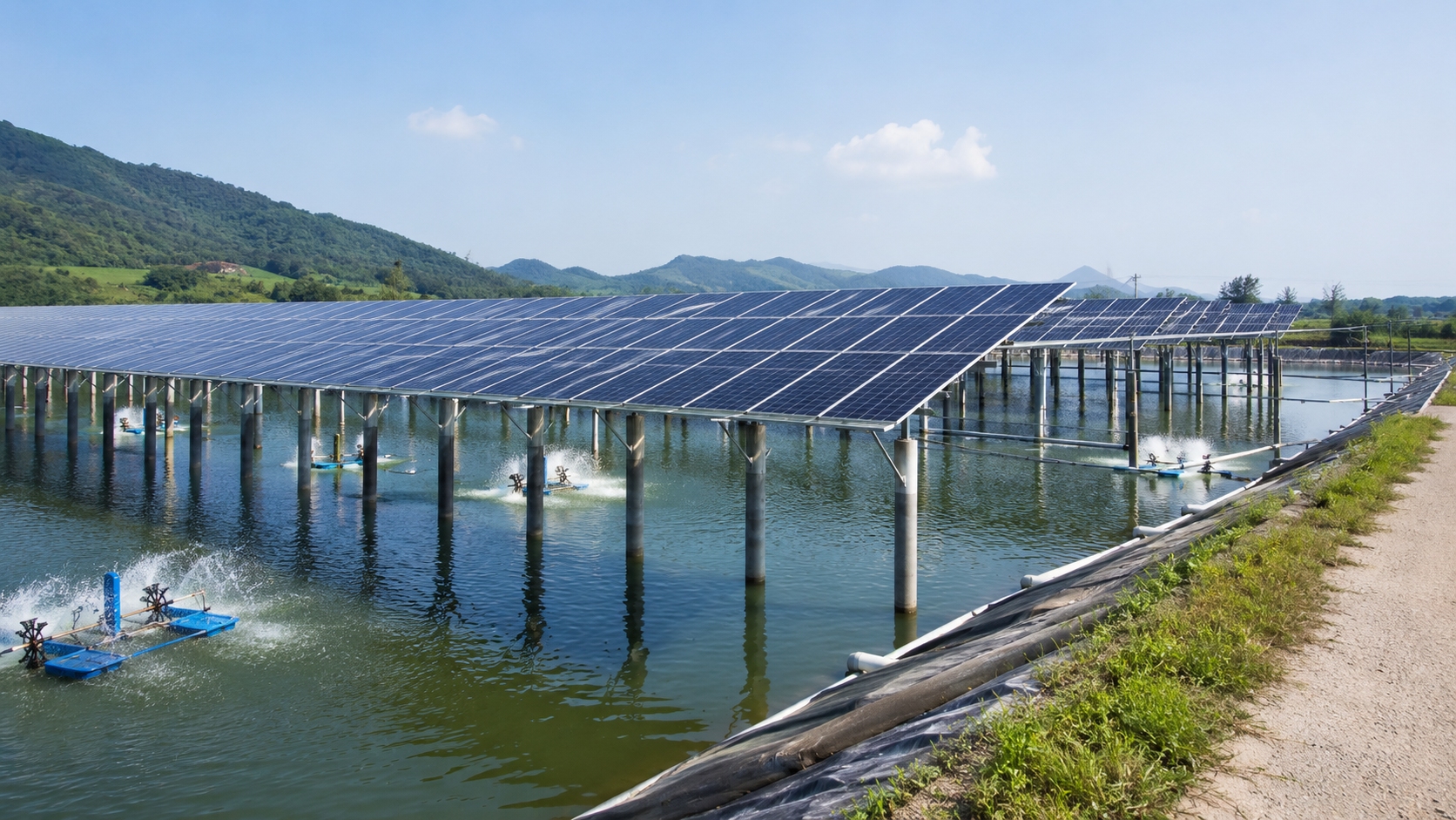
How to Solar Modules for Fishery PV Systems
For fishery PV systems, solar modules should be installed 2.5–3.5 m above the water surface, leaving enough space for feeding, netting, and boat access. Use double-glass, anti-corrosion modules with at least IP68 junction boxes. Keep 40–60% light transmission for aquaculture, set a 10–15° tilt angle, and inspect cables, brackets, and shading every month.
Humidity Protection
Waterproof Design
Module frame-to-glass sealing is the first physical barrier against moisture ingress. In a fishing-PV project I worked on at a near-shore aquaculture site, I encountered EL-visible microcracks caused by frame seal failure—investigation revealed that the sealing compound had aged prematurely under combined UV and moisture exposure, with module front-side power output degraded by 8.3%. During acceptance testing, we use IEC 61215 damp heat accelerated aging (DH1000) as the primary seal reliability screening, and additionally require passing the dual 85 test (85°C / 85% RH, 1000 hours) to verify frame stability under sustained humid heat conditions.
Sealed Area | Common Failure Mode | Recommended Design | Test Standard |
Frame corners | Stress concentration causing tearing | Two-module silicone reinforcement | IEC 61215 |
Glass-frame bond | UV aging debonding | UV-cured silicone | DH1000 |
Junction box bottom | Water immersion | Potting compound + waterproof gasket | IP67 verified |
Cable entry point | Moisture wicking along cable | Waterproof connector + silicone overmolding | IP68 certified |
Backsheet edge | Moisture reaching cells | Butyl tape double-seal | DH2000 enhanced |
Frame aluminum surface treatment also affects seal longevity. Anodized aluminum frames outperform standard spray-coated frames in salt spray resistance; for coastal projects, I require a 480-hour salt spray test report confirming no significant corrosion spots on the frame surface. For harsh near-shore sites, a C5-M rated anticorrosive coating is recommended.
Seal design must also account for thermal cycling fatigue. In inland lake fishing-PV projects with large day-night temperature swings, sealing compounds endure over 500 cycles annually from -20°C to 85°C. Standard silicone develops invisible microcracks after 1000 cycles; thermal shock-resistant modified silicone is recommended for such environments.
Sealing Materials
Three main sealing material types dominate the market: butyl rubber, EVA encapsulant, and silicone. Butyl rubber is commonly used in frame sealing, with a water vapor transmission rate (WVTR) of approximately 0.1 g/m²/day, demonstrating stable performance in IEC 61215 testing. EVA encapsulant is widely used in lamination processes, but requires attention to acidic byproducts in high-humidity environments—I once observed glass surface frosting caused by acetic acid released from EVA decomposition in a Zhejiang fishing-PV project. Silicone, valued for its flexibility and UV resistance, is typically used in junction box sealing applications.
1. Butyl rubber: excellent damp heat aging resistance; recommended for inner frame sealing; low WVTR ideal for high-humidity fishing-PV environments
2. EVA encapsulant: primary choice for module lamination; must be paired with silicone backsheet to neutralize acidic byproducts
3. Silicone: recommended for seam filling and junction box sealing; condensation-cure type is preferred over addition-cure for long-term durability
During project acceptance, requesting IEC 61853-1 spectral response test reports from module manufacturers helps evaluate material performance degradation curves under high UV exposure. Storage conditions for sealing materials also require strict control—butyl rubber stored above 30°C for extended periods undergoes premature aging, making incoming material inspection critical for sites lacking climate-controlled warehousing.
For offshore PV applications, PVB encapsulant may be considered as an alternative to EVA. PVB's WVTR is slightly higher (approximately 0.2 g/m²·day), but its superior hydrolysis stability provides markedly better long-term reliability in sustained high-humidity environments, justifying the marginal increase in laminated thickness.
Ventilation Guidelines
Complete sealing does not equal optimal protection. Module rear ventilation effectively reduces condensation risk on the inner glass surface while also suppressing Potential Induced Degradation (PID). In a Jiangsu fishing-PV project, I experimented with a no-ventilation design; after six months, EL testing revealed significant PID attenuation—the problem was only resolved after installing breathable vents on the module rear. In that project, peak PID attenuation reached 12%, severely impacting energy yield.
· Breather valve design: balances internal/external air pressure, prevents condensation inside a sealed cavity; EPTFE membrane material is recommended, water pressure resistance ≥0.1 bar
· Mounting tilt: ≥5° recommended to enable automatic condensation runoff; insufficient tilt causes water film retention and creates light transmission dead zones
· Rear clearance: a minimum 10 cm ventilation channel to remove moisture via air convection
· Junction box position: should be ≥500 mm above the maximum water level to prevent immersion damage
The breather valve quantity is determined by the module's rear projected area—generally one valve per 0.5 m². Too few valves result in insufficient ventilation and condensation; too many increase the moisture ingress risk. In eutrophic aquaculture water bodies, anti-algae clogging design for breather valves is also necessary.
Floating fishing-PV installations have gained maturity in recent years. Floatage displacement must be calculated based on the module weight, local maximum wind load, and water level variation, ensuring adequate safety margins during both high-water and low-water seasons. Float spacing must be uniform to prevent localized overloading and float rupture. In freeze-prone northern regions, compressible float connection designs are recommended to accommodate ice expansion forces.
Mounting Height
Avoiding Water Splash
The distance from the module's lower edge to the water surface or ground is a critical parameter for preventing splash from reaching the module's rear sheet. Based on field experience, a minimum clearance of 30 cm between the module's lower edge and the highest water level or splash zone is required. During on-site measurements in a Zhejiang fish pond project, I found that when ground clearance fell below 20 cm, splash from rain-season wave action caused severe salt accumulation on the rear glass—EL testing revealed large-area black spots on rear cells, with power attenuation nearly 6 percentage points higher than normal samples.
1. Ground clearance: ≥30 cm (avoids >95% of splash risk); coastal projects should increase to ≥50 cm for high tide conditions; high-wave areas may require up to 80 cm
2. Mounting angle: optimized per latitude, typically 10°–20°; insufficient tilt angle hinders self-cleaning from rain
3. Pillar corrosion protection: hot-dip galvanized or stainless steel material required; galvanized layer ≥85 μm to prevent rust-induced structural settlement
4. Water level gauge: install on a support structure for real-time monitoring and alert triggering
5. Pile foundation depth: Sub-aqueous pile depth must satisfy local geological requirements; in soft mud layers, depth should be increased to at least 1.5 × pile diameter
Note: Fish ponds typically host farmed fish or crustaceans whose activity causes localized water surface disturbance. Higher stocking density generates more frequent surface turbulence. In high-density aquaculture areas, consulting with aquaculture specialists during module design to understand fish activity patterns is recommended, with ground clearance adjusted accordingly.
Sunlight Exposure
The distance between modules and the water surface affects not only splash prevention but also the utilization efficiency of water-surface reflected light (albedo). Insufficient clearance blocks water-surface reflections, dramatically reducing the power generation gain from bifacial modules. Based on field measurements, when the module lower edge is 50–80 cm above the water surface, rear-side power gain can reach 10%–15% of front-side output. When spacing falls below 30 cm, rear gain drops sharply to below 5%, with the albedo effect nearly nullified.
· 50–80 cm spacing: optimal bifacial rear-gain range, balancing splash prevention and albedo utilization
· Avoiding surface vegetation obstruction: regular algae removal from the water surface; algae coverage can absorb >30% of reflected light
· Winter freeze impact: ice layer expansion may deform support structures; northern projects should set the lowest point ≥20 cm above the ice layer
· Wind direction impact: Support structure spacing on the dominant windward side should be increased to reduce continuous splash on rear surfaces
· Water depth impact: Deep water (>2 m) ponds have a surface albedo of approximately 5%–10%; shallow water (<50 cm) can reach >15%
In aquaculture zones, water surfaces often host algae or zooplankton. Decomposition of their waste products and dead organisms generates corrosive gases that accelerate metal corrosion on support structures. These factors should be incorporated into material selection during design; for submerged support structure sections, epoxy coating or cathodic protection may be necessary. Additionally, pH fluctuations during algae blooms (pH 9–10 possible) accelerate aluminum frame pitting corrosion—stainless steel support structures are recommended for high-algae-risk zones.
For precise albedo calculations, IEC 61853-2 spectral reflectance testing methods should be referenced. Different water quality types (freshwater / seawater / eutrophic water) show albedo differences of up to 5 percentage points, significantly impacting fishing-PV project energy yield projection models.
Maintenance Access
Adequate maintenance access is essential for the long-term reliable operation of fishing-PV systems. Pre-planning operation aisles between modules and array rows ensures worker safety and reduces maintenance costs. Across multiple fishing-PV project commissioning phases, I observed that insufficient aisle space drastically reduces module cleaning and fastener inspection efficiency—technicians unable to stand for direct inspection must rely on temporary scaffolding, extending single cleaning operations from the planned 2 hours to over 6 hours, severely impacting maintenance schedules.
1. Array aisle width: ≥80 cm to allow tool passage; wider aisles can accommodate small transport vehicles; dense arrays recommend ≥100 cm
2. Module lower edge height: ≥120 cm to ensure standing inspection space, avoiding bent-over postures that reduce efficiency and increase injury risk
3. Inverter and combiner box placement: positioned for easy access, ≥1 m from the water surface to prevent immersion damage
4. Cable tray and conduit routing: cable trays ≥50 cm above the water surface to prevent prolonged immersion and moisture-induced insulation failure
5. Safety guardrails: mandatory in high-water-level work areas to prevent personnel from falling into the water
Creating a maintenance aisle map during the design phase—specifying minimum widths for each aisle and agreeing on construction tolerance with the EPC contractor—is strongly recommended. For large-scale PV projects (capacity ≥10 MW), a service road width ≥3.5 m should be reserved to allow maintenance vehicles to enter the array interior for equipment replacement and large-scale cleaning operations.
For floating PV projects, maintenance personnel typically conduct patrols and cleaning by boat. Float spacing should account for small-scale repair operation space, with a minimum 60 cm working gap recommended to allow the use of electric torque wrenches and similar tools for fastener re-tightening.
Salt Mist Resistance
Anti-Corrosion Coatings
Salt spray corrosion represents one of the greatest challenges for coastal fishing-PV systems. IEC 61768 specifies salt spray test methods for PV modules in marine environments, requiring that after 1000 hours of continuous 5% NaCl solution spray at 35°C, module power attenuation does not exceed 5%. Coating system selection directly determines support structure and fastener service life in salt spray environments—I once observed a coastal fishing-PV project where modules using standard galvanized supports showed a 40% rust corrosion rate after only three years, while a simultaneous project using HDG + polyester coating system maintained excellent structural condition.
Coating Type | Test Standard | Application Scenario | Recommended Warranty | Thickness Requirement |
Hot-dip galvanizing (HDG) | ISO 1461 | Near-shore / inland freshwater | 15 years | ≥85 μm |
Powder coating | ISO 12944 | Inland freshwater | 10 years | 60–80 μm |
HDG + polyester topcoat | C5-M rated | High salt spray coastal | 20 years | ≥120 μm |
Stainless steel 304 | ASTM A240 | High salt spray coastal | 25 years | — |
Stainless steel 316L | ASTM A240 | Severe salt spray zone | 30 years | — |
Epoxy zinc-rich + PU topcoat | C5-M rated | 1–5 km from the coastline | 25 years | ≥160 μm |
Coating application quality directly impacts support structure longevity. Post-HDG chromate passivation treatment (using a trivalent chromium passivation solution) significantly improves white rust resistance. Polyurethane topcoat offers superior UV resistance compared to polyester — it should be prioritized in high-UV coastal zones. After coating application, adhesion testing (cross-cut test) is mandatory to ensure the coating firmly bonds to the substrate and resists peeling in salt spray environments.
For submerged support structure sections—such as connecting members in floating PV installations—coating selection is even more critical. Submerged-grade epoxy coatings or glass flake coatings are recommended, as their WVTR is an order of magnitude lower than standard epoxy coatings, effectively preventing chloride ion penetration to the metal substrate surface.
Regular Cleaning
Module cleaning frequency in salt spray environments must be significantly higher than in inland projects. NaCl crystal accumulation on glass surfaces forms diffuse reflections, substantially reducing light transmittance. Operating records from a Hainan coastal fishing-PV station showed that arrays cleaned monthly versus quarterly cleaning had an annual energy yield difference of 8%—during high salt spray seasons (typically October–November after typhoon seasons), salt deposit accumulation is fastest; without timely cleaning, light transmittance losses can exceed 15%.
· Cleaning frequency: monthly for high salt spray zones; quarterly for moderate zones; semi-annually for inland freshwater areas
· Cleaning tools: soft mops or automatic cleaning equipment; hard brushes that may scratch glass coatings must be avoided
· Cleaning timing: early morning or evening is preferred; avoid high temperature differentials that may cause thermal shock and glass breakage
· Water quality requirement: freshwater rinsing is recommended; high salt content in cleaning water causes secondary salt deposits on glass
· Cleaning records: document light transmittance recovery after each cleaning to build a cleaning effectiveness tracking archive
For large-scale PV projects (≥5 MW), automated cleaning robots may be considered, but robot weight must not exceed the module load design value (typically 17 kg/m²). Robot travel paths should be pre-planned in CAD models to avoid collisions with support structures or tipping over in floating array installations. Robots with built-in fall-protection automatic shutdown are recommended.
Fastener Inspection
Support structure fasteners are the most overlooked yet most failure-prone modules in fishing-PV systems. In high salt spray environments, stainless steel fastener passive films gradually degrade, leading to pitting corrosion—corrosion that is visually difficult to detect but significantly reduces thread strength. During project inspections, I have frequently found that after typhoon or strong wind seasons, some fasteners exhibit torque attenuation exceeding 15%. Without timely re-tightening, this leads to support loosening and potentially module falling, causing safety incidents and energy production losses.
1. Re-tightening cycle: every 6 months in high salt spray zones; immediate special inspection after typhoons or strong wind events
2. Torque records: maintain torque archives and compare data from each re-inspection; replacement is required when torque drops >10%
3. Replacement material: 316 stainless steel fasteners are the minimum requirement for coastal projects; 316L is recommended for near-shore projects to enhance pitting corrosion resistance
4. Lubrication protection: apply an anti-seize compound (copper-based recommended) to the threads to prevent salt spray adhesion causing difficult disassembly
5. Corrosion caps: install plastic anti-corrosion caps on exposed bolt heads to reduce salt spray direct contact area
Incorporating fastener torque inspection into annual maintenance contracts—as a formal acceptance criterion with documented written reports—is strongly recommended. For floating fishing-PV support structures, additional inspection of fasteners connecting floats to support frames is necessary. This area undergoes continuous immersion, where fastener corrosion rate is 2–3× faster than in atmospheric conditions; a double-nut + lock washer combination is recommended to ensure a reliable connection.
Note: Fishing-PV projects require IEC 61215/61730 certification, IEC 61853 salt spray testing, moisture barriers, sufficient clearance, and anti-corrosion coatings to ensure reliable 25-year performance.