Monocrystalline PV Module Maintenance | Cleaning & Care Guide
To ensure the 25-year operational efficiency of monocrystalline modules and mitigate the risk of a 15% power generation loss caused by dust accumulation, it is recommended to clean them with soft water (TDS < 50 mg/L) when irradiance is below 200 W/㎡.
Timing & Frequency
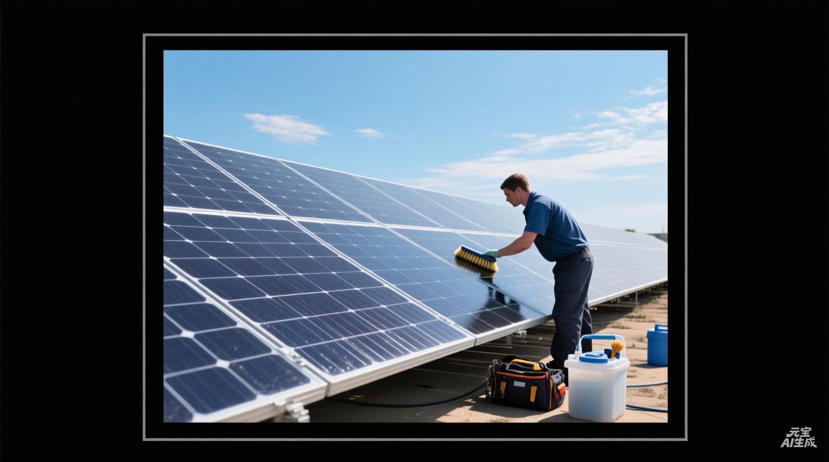
Monocrystalline silicon modules must be cleaned when the panel temperature is below 30 degrees Celsius, typically before 7:00 AM.
At this time, natural dew can soften dust accumulation approximately 50 microns thick. In arid regions like Arizona, dust removal is required every 90 days to prevent output power from dropping by more than 6%.
If the inverter monitors a Performance Ratio (PR) lower than 0.80, or if the installation tilt angle is less than 10 degrees (causing rain-driven self-cleaning to fail), the cleaning frequency should be increased by 1 to 2 times to ensure photoelectric conversion efficiency remains above 95% of the nominal value.
Avoiding High-Temperature Periods
On clear afternoons when ambient light intensity reaches 1000 watts per square meter, the dark surfaces of monocrystalline silicon modules absorb significant infrared radiation.
This causes the glass cover and internal solar cells to rapidly rise to temperatures between 60 and 75 degrees Celsius, while the temperature of standard tap water or demineralized water typically remains between 15 and 25 degrees Celsius.
When liquid with a temperature difference exceeding 40 degrees Celsius contacts high-temperature tempered glass, a massive instantaneous thermal stress is generated within the material.
The cover glass used in monocrystalline silicon modules is typically low-iron, high-transmittance glass that has undergone physical tempering. It possesses a balanced internal pre-stress structure.
Rapid surface cooling causes the outer layer of the glass to shrink sharply, while the inner layer remains in a high-temperature expanded state.
Once the glass integrity is compromised, water vapor enters the module through the cracks, leading to EVA film delamination and busbar corrosion, ultimately causing the entire panel to be scrapped prematurely.
Monocrystalline silicon cells themselves are also very fragile, with a thickness usually between 160 to 180 microns. In a high-temperature state, the lattice structure of the silicon wafer is in an expanded state.
If sprayed with cold water at this time, the rapid and uneven cooling creates stress concentration points in the cell, inducing micro-cracks.
These micro-cracks may not significantly reduce power initially, but under subsequent day-night temperature cycles and wind loads, the cracks will continue to extend, cutting off current transmission paths and forming hot spots on the module surface.
Experimental data shows that cleaning with cold water between 12:00 PM and 2:00 PM increases the probability of permanent structural damage to the module by more than 80% compared to early morning. Such damage is classified as physical damage and is usually not covered by the manufacturer's warranty.
· Evaporation Speed & Mineral Residue: When water is sprinkled on a high-temperature panel, it evaporates in an extremely short time. For cleaning water that has not undergone ultrafiltration, the calcium and magnesium ions will crystallize rapidly as the water evaporates, forming white hard limescale on the glass surface.
· Data Loss in Power Generation Efficiency: A 0.1 mm thick layer of limescale can block approximately 5% to 12% of incident light. Since monocrystalline silicon modules are typically connected in series, a small area of localized scale shading will drag down the current output of the entire string through the "Barrel Effect," leading to a significant drop in string revenue.
· Chemical Reactions of Cleaning Agents: If cleaning solutions containing surfactants are used at high temperatures, the heat accelerates the activity of the chemical modules or even causes chemical decomposition. The chemical film remaining on the glass surface changes the refractive index of the glass, further reducing the number of effective photons entering the cell.
From an operational safety perspective, rooftop or ground-mount environments during high-temperature periods are also extremely unfriendly to personnel.
The aluminum alloy frames of monocrystalline silicon modules also absorb a large amount of heat from the sun, with contact temperatures potentially exceeding 60 degrees Celsius.
· Thermal Equilibrium Recovery Time: It is suggested to wait at least 1.5 to 2 hours after sunset to allow the modules to dissipate accumulated heat until their temperature is close to the ambient atmospheric temperature.
· Morning Natural Wetting Effect: Between 5:00 AM and 7:00 AM, the air humidity is higher, and a thin layer of natural condensation dew often forms on the panel surface. This dew effectively weakens the adhesion between dust and glass. Rinsing with water at this time allows for the removal of more dirt with less water pressure and volume, increasing efficiency by more than 40% compared to dry, high-temperature periods.
· Inverter Monitoring Feedback: Before planned cleaning, observe the real-time DC voltage and current data from the inverter. If the modules are in a high-temperature state, their internal resistance increases and the voltage decreases. Forced cleaning at this time causes violent fluctuations in circuit parameters, placing unnecessary adjustment burdens on the inverter's Maximum Power Point Tracker (MPPT).
The thermal expansion coefficient of tempered glass is approximately 9 x 10^-6 per degree Celsius.
Under a temperature difference of 40 degrees Celsius, a 2-meter-long module surface will produce an instantaneous deformation displacement of approximately 0.72 mm.
Although this value seems small, for the silicon wafers and connecting wires laminated beneath the glass, this sudden pull is enough to cause fatigue failure of the internal physical structure.
Maintaining the difference between the module temperature and the water temperature within 20 degrees Celsius is the industry-recognized baseline for safe operation.
In actual project management for large-scale monocrystalline silicon power plant O&M, strict morning and evening shift systems are usually established.
The morning shift typically starts at 5:30 AM and ends at 9:30 AM; the evening shift starts at 6:30 PM and continues into the night.
This arrangement avoids periods of peak UV radiation and utilizes the low-temperature window of the modules, ensuring the cleaned glass surface is as clear as new without leaving mineral spots or water marks, thereby maintaining the system's PR at the upper limit of design standards.
Regional Frequency Variations
Experimental data shows that in the absence of rainfall, module surfaces in these areas accumulate approximately 0.4 to 0.8 grams of fine dust per square meter daily.
This accumulation can reduce light transmittance by more than 15% in just three weeks.
For monocrystalline silicon, a material extremely sensitive to spectral response, slight infrared blocking causes disproportionate current losses.
In Nevada test sites, if dust removal is not performed for 60 consecutive days, the overall system PR typically drops from 0.85 to below 0.70.
Therefore, during the dry season, the maintenance cycle must be shortened to once every 30 to 45 days.
In the event of a sandstorm, emergency intervention must be carried out within 48 hours after the storm ends to prevent fine sand from physically adhering under the action of morning dew, forming a difficult-to-remove calcified layer.
Environmental Characteristics | Deposition Rate (g/m²/month) | Suggested Cleaning Cycle (Days) | Potential Power Loss (No Cleaning/Month) |
Extreme Desert/Arid | 12.0 - 25.0 | 30 - 45 | 18% - 25% |
Coastal/Salt Spray | 2.5 - 5.0 | 60 | 8% - 12% |
Industrial/Logistics Hub | 4.0 - 8.5 | 90 | 10% - 15% |
Temperate Agri/Forest | 1.0 - 3.0 | 180 | 3% - 6% |
Urban Residential | 1.5 - 4.0 | 180 | 5% - 8% |
In coastal areas, such as the Florida peninsula or the North Sea coast, although rainfall is frequent, high concentrations of sodium chloride particles in the air are the main factor affecting cleaning frequency.
Once salt spray crystallizes on the surface of monocrystalline silicon modules, it forms a translucent white film.
This crystalline substance not only blocks light but its hygroscopicity also keeps the glass surface slightly damp for long periods, attracting more airborne suspended matter.
For power plants within 500 meters of the coastline, salt deposition occurs at a rate of approximately 2 grams per square meter per month.
If a cleaning frequency of every 60 days is not maintained, salt crystals will undergo electrochemical reactions with the sealant at the edge of the backsheet, increasing the system's leakage current.
Data shows that coastal modules regularly rinsed with demineralized water have an average annual power generation efficiency about 9% higher than modules relying solely on rain for self-cleaning.
Environments around industrial areas and large logistics hubs present different pollution characteristics.
Pollutants here are mainly unburned hydrocarbons, carbon black particles, and fine rubber dust from heavy truck emissions.
These particles are often oily and have a particle size mostly below 2.5 microns, making them easily adhere to the anti-reflective coating (ARC) of the monocrystalline silicon glass through electrostatic attraction.
Observations in the Ruhr region of Germany or the Chicago industrial corridor in the US show that this oily dust has an extremely high absorption rate for short-wave light. Just two months of accumulation is enough to reduce the module's short-circuit current (Isc) by more than 7%.
For such environments, a 90-day cleaning frequency is the optimal balance point for maintaining ROI.
Furthermore, since oily substances are hydrophobic, simple rainwater rinsing often only removes surface dust and fails to remove the underlying oil film, making manual intervention indispensable.
· Agriculture & Biological Pollution: In agricultural areas of France or the US Midwest, peak pollen release can reach tens of thousands of particles per cubic meter. Pollen is highly sticky and, once in contact with morning dew, forms a hard yellow layer on the glass. Additionally, bird droppings are a major source of localized hot spot effects. A single bird dropping covering only 3 square centimeters can cause the output current of all monocrystalline cells in that series circuit to drop by more than 20%.
· Tilt Angle Correction for Frequency: Flat-mounted modules with an installation angle between 5 and 10 degrees accumulate dust 2.5 times faster than modules with a 30-degree tilt. This is because the runoff speed of rainwater at low tilt angles is insufficient to generate enough shear force to carry away pollutants. In temperate marine climates like London, UK, even with abundant rain, it is recommended to conduct a manual inspection every 120 days for flat-mounted monocrystalline modules to prevent the formation of mud belts at the bottom frame.
Region Type | Main Pollutant Modules | Physical Characteristics | Cleaning Difficulty |
Agricultural | Pollen, pesticide residues, bio-slime | Highly sticky, seasonal outbreaks | Requires neutral cleaning agents |
Urban | Traffic exhaust, construction dust | Wide particle size distribution, contains metallic particles | Surface prone to fine scratches |
Polar/High Latitude | Snow accumulation, ice layers, atmospheric deposition | High albedo, low-temperature solidification | Hot water de-icing strictly prohibited |
Snow accumulation exceeding 3 cm will cause monocrystalline silicon modules to stop generating electricity entirely due to opacity. In this case, maintenance frequency should be based on weather forecasts rather than days.
In seasons with heavy snowfall, if the tilt angle of the monocrystalline silicon module exceeds 35 degrees, some snow will slide off via gravity.
However, snowmelt that refreezes at around 0 degrees Celsius will form ice dams at the lower edge of the module. This not only blocks sunlight but may also squeeze the aluminum alloy frame due to the expansion force of the ice.
In this environment, maintenance focus is on timely post-snow cleanup to ensure that the drainage holes at the lower edge are not blocked by ice, thereby maintaining the system's minimum output under weak winter light.
In European markets with high electricity prices, even a 2% efficiency improvement can offset the labor cost of an additional cleaning.
Through sampling analysis of 3,000 monocrystalline silicon power plants worldwide, plants that maintain a PR above 0.82 have an asset depreciation rate approximately 15% slower than those with poor maintenance.
If this ratio deviates from the factory nominal curve by more than 5%, a cleaning procedure should be initiated regardless of whether the scheduled cycle has been reached.
Data Monitoring Intervention
A standard monitoring system collects data from the inverter every 5 to 15 minutes and compares it with the on-site irradiance meters.
For high-performance monocrystalline silicon modules, the Performance Ratio (PR) is the primary indicator for evaluating whether cleaning is needed.
Ideally, a monocrystalline system in southern Spain should maintain a PR between 0.82 and 0.85 upon initial installation.
If the monitoring backend shows that this value has fallen below 0.78 for three consecutive days (excluding efficiency drops caused by cloud cover or high ambient temperatures), then light loss due to surface dust becomes the primary cause.
In a 10 MW monocrystalline silicon power plant experiment in California, when the monitored daily power generation was 4% lower than the predicted value, the power gain after cleaning immediately covered the labor costs of the cleaning. If intervention is delayed until the power generation drop reaches 10%, although the number of cleanings is reduced, the lost electricity revenue will far exceed the saved maintenance costs.
In addition to macro PR analysis, string-level current monitoring for monocrystalline modules provides more granular grounds for intervention.
Monocrystalline modules often use multi-busbar designs to reduce internal resistance, but this makes them very sensitive to localized shading.
If the monitoring platform finds that the current of a specific string is more than 0.5 amperes lower than other strings on the same rack, this usually does not indicate module damage, but rather a large area of bird droppings or localized mud accumulation on a panel in that string.
This unbalanced current performance causes the inverter's Multi-MPPT function to jump frequently as it attempts to find a new output equilibrium point.
By analyzing the current deviation between strings, the system automatically generates a "cleaning task list" with coordinates, directing staff to handle specific localized shading. This "precision strike" model can reduce non-scheduled downtime for monocrystalline power plants by more than 20%.
Typical short-circuit currents for monocrystalline modules are between 10A and 13A. In actual cases, a hard stain occupying only 2% of the total panel area can cause voltage fluctuations across the entire string exceeding 15 Volts. Using the SCADA system to capture these minute signal anomalies is an effective intervention method to prevent hot spots.
In some high-end European power plant configurations, dedicated Soiling Sensors are integrated directly into the monitoring network.
This sensor consists of two identical monocrystalline reference cells: one is kept absolutely clean by an automatic cleaning device, while the other is exposed to the environment for natural dust accumulation.
By comparing the short-circuit current difference between these two reference cells, the system derives a precise "Soiling Loss Index."
According to industry-recognized standards, when this index reaches 0.03 (i.e., a 3% output loss), the system automatically issues an intervention command.
This quantitative analysis method eliminates the subjectivity of manual judgment. In arid Arizona, this sensor-based intervention model has been proven to increase the annual average ROI of monocrystalline systems by approximately 1.5%.
Since the laboratory conversion efficiency of monocrystalline silicon wafers is as high as 24% or more, every 0.1% of dust loss is a significant financial expense in long-term asset management.
Data records from an Australian inland power plant show that during a 90-day rainless season, if no monitoring intervention is performed, fine dust on the monocrystalline surface forms a film about 20 microns thick. This film reduces the module's Fill Factor (FF) from 0.80 to 0.74, leading to a massive shrinkage in overall output power.
The intervention logic for monocrystalline modules also includes the integration and analysis of historical meteorological data.
Sophisticated O&M platforms fetch weather forecasts for the next 72 hours.
If the monitoring data shows that the current soiling loss has reached the trigger threshold, but the meteorological system predicts rainfall exceeding 5 mm within 24 hours, the system will suggest postponing manual intervention to utilize the rain's self-cleaning effect and save costs.
However, if light rain or trace precipitation is predicted, the system will accelerate the intervention schedule.
This is because trace precipitation often turns dry floating dust into sticky mud, which, after drying, forms even more stubborn stains on the monocrystalline surface.
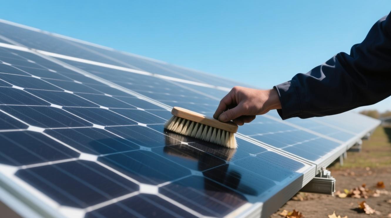
Professional Cleaning Tools
For the anti-reflective coating on monocrystalline silicon, which is approximately 150 to 200 nanometers thick, professional tools must meet strict quantitative standards.
The bristle diameter should be between 0.05 and 0.1 mm, used in conjunction with deionized water (TDS less than 50 ppm).
The mechanical pressure during a single cleaning must be maintained below 15 kg per square meter to prevent micro-damage.
These tool specifications aim to ensure that the annual power attenuation of the PV system is controlled within the standard range of 0.45% to 0.55%.
Brush Material & Physical Specifications
Mainstream professional brush heads generally use Polybutylene Terephthalate (PBT) or Nylon 66 as the base material.
PBT material has an extremely low water absorption rate, usually kept below 0.1%.
This allows the bristles to maintain their original rigidity and resilience even under prolonged immersion or humid environments, preventing them from collapsing due to increased weight.
In contrast, ordinary plastic bristles experience a drop in flexural modulus of more than 30% after 2 hours of contact with water.
Professional-grade PBT bristles have a melting point as high as 223 degrees Celsius. Even when performing dry cleaning on module surfaces that reach 75 degrees Celsius in summer, the bristles will not soften or stick to the glass.
· Bristle Diameter Standard: Professional maintenance requires bristle diameters to be precisely controlled between 0.08 mm and 0.12 mm.
· Tensile Strength: High-quality bristles should have a tensile break strength greater than 450 MPa, ensuring no breakage residues are produced during high-speed rotation and friction.
· Bend Recovery Rate: After 500 hours of continuous operation, the vertical recovery rate of the bristles must reach over 95% to ensure consistent and uniform contact pressure.
· UV Stability: 2% to 3% UV stabilizers must be added to the material to ensure that after 1000 hours of simulated sunlight exposure, the material embrittlement rate is below 5%.
Monocrystalline silicon modules are coated with a layer of Silicon Dioxide Anti-Reflective Coating (ARC) only 100 to 150 nanometers thick, which is very fragile.
To protect this thin film, professional brush heads employ tapered bristle technology or flagging.
This mechanically splits the end of each bristle into 3 to 5 finer fibers, making the tip of the bristle feel like human hair.
This design significantly increases the microscopic contact area between the brush head and the glass surface.
Experimental data shows that flagged brush heads, under the same downward pressure, have a removal rate for fine dust below 5 microns that is 40% higher than ordinary straight bristles, while keeping the friction coefficient of the glass surface at around 0.2—well below the threshold for creating scratches.
· Tufting Density: The number of tufting holes per square centimeter should be maintained between 30 and 45 to form a high-density cleaning array.
· Arrangement Pattern: Staggered V-shaped or spiral arrangements are used. This structure creates a continuous "mud-pushing" effect as the brush head moves, preventing dirt from accumulating inside the brush.
· Tuft Retention: The pull-out force for a single tuft must be greater than 10 kg to prevent shedding when cleaning stubborn dirt like bird droppings.
· Total Brush Width: Brush heads for manual poles are typically 40 cm to 60 cm wide, while automated robot brush heads can reach 120 cm to 200 cm.
Monocrystalline silicon wafers are extremely thin, usually around 160 microns. Excessive vertical pressure can cause invisible micro-cracks.
The total weight of professional cleaning brush systems is usually controlled between 1.5 kg and 2.5 kg, distributed over a contact surface of 0.24 square meters, generating a static pressure of less than 100 Pascals.
This is not only far below the 2400 Pascal static load limit defined by IEC 61215 but also leaves a sufficient safety margin to prevent instantaneous impact caused by uneven force from the operator.
1. Static Suppression: A small amount of conductive fiber (such as 0.5% carbon fiber) is mixed into the bristles during production to export electrostatic charges generated by friction, preventing them from attracting secondary dust.
2. Chemical Resistance: Materials must pass chemical resistance tests with pH values from 4 to 10 to ensure no chemical degradation occurs when using neutral or weakly alkaline cleaners.
3. Shock-Absorbing Base: Brush bases are typically reinforced with Polypropylene (PP) and wrapped with a 5 mm thick layer of EPDM rubber on the edges to prevent metal parts from accidentally hitting the module frame or glass edges.
4. Dynamic Balance: For electric rotating brushes, the dynamic balance deviation must be less than 5 grams to eliminate negative impacts of high-frequency vibration on the structural integrity of the silicon wafer.
Standard bristle length is set between 50 mm and 65 mm.
If the bristles are too short, flexibility decreases, leading to reduced coverage of the module's edge grooves.
If they are too long, centrifugal force causes the bristles to flare out during rotation, diluting the effective cleaning force per unit area.
Through laboratory testing of 5,000 reciprocating wiping cycles, this specific length of PBT brush head has an impact of less than 0.05% on the light transmittance of the glass, effectively maintaining the light-harvesting capability of the original design.
When bristle wear exceeds 15% of the original length, or when the flagged structure at the end becomes blunt due to wear, the brush must be replaced.
Continuing to use excessively worn brushes not only extends cleaning time by 25% but also increases the risk of scratching the module surface because the base of the bristles is harder.
Professional maintenance teams are usually equipped with bristle durometers to ensure that the tools in use always remain within the Shore A 45 to 55 hardness range across different seasons and temperatures.
Pure Water Treatment Systems
Typical municipal tap water has Total Dissolved Solids (TDS) between 150 and 400 ppm.
The dissolved calcium, magnesium, sodium, and bicarbonate ions in this water will form hard white limescale or spots on the module surface after evaporation.
The anti-reflective coating on monocrystalline silicon is only about 120 nm thick; these mineral deposits not only cause a 0.2% to 0.5% loss in light transmittance but may also trigger localized thermal stress due to uneven heating.
Professional pure water systems are designed to reduce the output TDS to below 50 ppm through multi-stage filtration, or even below 1 ppm when aiming for ultimate results.
Water Type | TDS Index (ppm) | Conductivity (μS/cm) | Evaporation Residue (mg/L) | Impact on Monocrystalline Modules |
Tap Water | 150 - 450 | 300 - 900 | 150 - 450 | Prone to visible scale; requires physical drying |
RO Water | 5 - 20 | 10 - 40 | 5 - 20 | Meets over 90% of cleaning needs |
DI Water | 0 - 5 | 0.1 - 10 | < 5 | Ultimate clean; trace-free; for precision maintenance |
Ultrapure Water | < 0.1 | < 0.1 | Near Zero | Used in labs or semiconductor-grade cleaning |
Reverse Osmosis (RO) technology is the backbone of pure water systems.
This process uses a semi-permeable membrane under pressure higher than osmotic pressure (typically 0.5 to 1.0 MPa) to force water molecules through pores only 0.0001 microns in size, while 95% to 99% of dissolved minerals, bacteria, and organics are intercepted and discharged in the concentrate stream.
For field operations at monocrystalline power plants, RO systems must be equipped with high-pressure pumps to maintain stable production.
For every 1-degree Celsius drop in inlet water temperature from 25 degrees, production decreases by about 3%; thus, professional equipment often integrates thermal compensation or oversized membranes.
In practice, the ratio of product water to wastewater (recovery rate) is generally set between 1:3 and 1:1 to ensure the membrane surface does not scale or clog due to high salt concentration.
To further enhance purity, deionization (DI) systems are often used as a post-treatment step after RO. This technology uses a mixed-bed ion exchange resin, filled with positively charged cation resins and negatively charged anion resins.
As RO water flows through the resin layer, remaining trace calcium and magnesium ions are captured and replaced with hydrogen and hydroxide ions, which combine to form pure water molecules.
This process can reach a resistivity level of 18 Megohm-cm. Using such water for monocrystalline modules completely eliminates the need for subsequent squeegeeing, as the surface is left extremely clean after evaporation.
However, resin capacity is limited. Each liter of mixed resin typically treats 1,000 to 2,000 liters of RO pre-treated water.
Operators must monitor water quality via online conductivity meters; once the reading exceeds 10 μS/cm, the resin canister must be replaced.
Filtration Stage | Filter Material | Precision (μm) | Replacement Cycle (Gal/Month) | Primary Protected Object |
1: Sediment | Polypropylene (PP) | 5 | 10,000 - 15,000 | Prevents sand from clogging RO membrane |
2: Active Carbon | Granular Carbon (GAC) | 10 | 15,000 | Absorbs chlorine to prevent RO oxidation |
3: RO | Polyamide Composite | 0.0001 | 24 - 36 Months | Removes >98% of dissolved solids |
4: DI | Mixed Nuclear Grade Resin | Molecular | Based on TDS meter | Achieves zero mineral residue |
A carbon fiber pole system equipped with dual brushes typically requires a supply of 4 to 8 liters per minute.
If the supply is insufficient, the spray pressure at the brush head will drop below 0.1 MPa, leading to a thin lubrication film between the bristles and the glass, increasing the risk of physical wear.
To ensure continuous supply during high-intensity operations, professional equipment is equipped with 50- to 100-liter buffer tanks and uses automatic pressure-sensing pumps to maintain outlet pressure between 0.3 and 0.5 MPa.
In cold environments, water viscosity increases and RO membrane flux drops significantly; at this time, pump frequency or pressure valves must be adjusted.
In hot, dry environments, if the cleaning water TDS fluctuates, the evaporation speed on the module surface may be faster than the dissolution process, leading to localized white circles.
Therefore, operators need high-precision handheld TDS pens to sample the outlet every two hours. If the TDS exceeds the initial setting by 20%, filters or membranes must be checked for clogging or scaling.
Carbon Fiber Telescopic Poles
Professional maintenance currently utilizes T700 or T800 high-modulus carbon fiber as the primary material, with carbon content usually exceeding 95% and a density of only 1.6 to 1.8 g/cm³.
Compared to traditional aluminum poles, this material reduces weight by more than 40% for the same strength.
For a fully extended pole reaching 15 meters, the total weight can be controlled between 2.5 and 3.2 kg, allowing a single operator to work continuously for 4 to 6 hours without muscle fatigue causing uncontrolled pressure on the modules.
The tensile modulus of carbon fiber is typically between 230 and 240 GPa. This extreme rigidity ensures that deflection is limited to a very small range when the pole is extended horizontally or vertically.
T700 carbon fiber tensile strength reaches 4900 MPa.
A 10-meter carbon fiber pole weighs approximately 1.9 kg.
Wall thickness is usually kept at 0.8 to 1.2 mm.
The maximum diameter of the base section is generally 46 to 52 mm.
Poles are usually designed with 6 to 10 telescopic sections, each about 1.5 to 1.8 meters long.
The overlap length between sections is the physical basis for maintaining overall rigidity; professional equipment requires an overlap of at least 150 mm to prevent wobbling when fully extended.
This overlap design, combined with high-precision internal diameter tolerance control (usually less than 0.05 mm), ensures uniform force distribution during pushing and pulling. The clamping mechanisms at the joints are often made of reinforced Nylon 66 with 30% glass fiber.
This composite maintains a dimensional change rate below 0.1% across temperatures from -20 to 60 degrees Celsius, providing a stable locking force (usually exceeding 500 Newtons) to prevent accidental retraction during work.
Overlap length must reach at least 15 cm.
Clamp locking force must withstand over 50 kg of thrust.
Nylon clamps are resistant to high-temperature creep.
The diameter difference between sections is maintained at about 3 mm.
In monocrystalline power plant operations, the integrated water delivery system inside the pole needs to work with high-pressure pumps.
Internal hoses are often made of polyurethane (PU), with an outer diameter of 8 mm and an inner diameter of 5 mm.
This specification ensures sufficient flow (6 to 10 liters per minute) while minimizing total system weight.
The hoses must have a pressure rating of 0.6 to 1.0 MPa to handle instantaneous fluctuations.
Since carbon fiber is highly conductive, safety standards require a fiberglass/epoxy insulation section of at least 2 meters at the base of the pole when working near inverters or high-voltage lines.
This structure is tested with 100 kV DC high-voltage discharge to block induced currents and protect ground operators.
Because monocrystalline modules are sensitive to mechanical stress, pressure feedback devices at the pole tip are becoming common.
By embedding small sensors at the brush connection, operators can view the actual downward pressure on the glass in real-time.
Standard procedures recommend maintaining pressure between 5 and 15 Newtons; exceeding 20 Newtons increases the probability of micro-cracks by more than 0.5%.
The high-frequency vibration damping properties of carbon fiber help absorb friction vibrations, preventing high-frequency stress from reaching the silicon structure.
In high winds (Level 10), carbon fiber poles typically show 60% less deflection than aluminum poles, maintaining a 98% cleaning coverage rate.
For daily maintenance, the surface of carbon fiber poles is usually covered with a wear-resistant 3K plain or twill weave layer.
Each quarter, a circumferential hardness test should be performed; if the roundness deviation of any section exceeds 1 mm, it indicates internal fiber fracture and the section must be replaced.
With frequent use, the lifespan of a telescopic pole is 3 to 5 years. If the anti-corrosion coating peels off, carbon fiber will be exposed to UV, causing the epoxy matrix to embrittle.
Therefore, when not in use, poles should be stored in a shaded, ventilated rack with around 15% rated storage humidity.
Key Inspection Points
According to the IEC 61215 international standard, regular inspections can reduce power generation loss by approximately 15%.
The focus is on the physical state of the monocrystalline silicon wafers, ensuring drainage holes are clear and module gaps are maintained between 10 and 20 mm. Bolt torque should be kept between 8 and 10 Nm.
When surface dust causes a current output drop of more than 3%, cleaning should be performed immediately to prevent localized overheating.
Physical Damage Inspection
Monocrystalline modules typically consist of 3.2 mm ultra-clear tempered glass, EVA film, solar cells, a TPT backsheet, and an aluminum frame. In practice, the integrity of the glass surface is the first priority.
Ultra-clear tempered glass has a light transmittance above 91%; scratches deeper than 0.5 mm cause light scattering, reducing light intake for the cells below and dropping current by 1.5% to 2%.
If star-shaped or spider-web cracks larger than 3 mm in diameter are found, moisture will seep in.
This can drop insulation resistance from a normal 1000 MΩ to below 400 MΩ.
In 1500 V DC systems, this triggers leakage currents and inverter insulation alarms. In hail-prone areas, glass must be verified to withstand impacts from 25 mm diameter hail at 23 m/s.
Glass Damage Category | Detection Standard / Quantified Data | Specific Impact on Performance |
Surface Scratches | Depth > 0.5 mm | Localized light loss; current deviation 1.5% - 2% |
Physical Fractures | Any penetrating crack size | Insulation drop; leakage risk; system shutdown |
Surface Delamination | Edge separation > 5 mm | Moisture ingress causing internal circuit corrosion |
Residue/Soiling | Dust > 20 g/m² | Non-linear efficiency drop 5% - 15% |
Common TPT or KPC backsheets may yellow after 10 years of UV exposure. If bubbles larger than 5 mm are observed, it indicates delamination between the EVA and the backsheet.
This reduces heat dissipation, raising cell operating temperatures by 5 to 8 degrees Celsius. For every 1-degree increase, monocrystalline output power drops by about 0.39%.
Inspections should also look for burn marks on the backsheet. These black spots, often only 3 to 5 mm in size, indicate severe hot spots where localized temperatures may have exceeded 100 degrees Celsius.
Backsheet Abnormalities | Technical Description | Long-term Consequences |
Surface Yellowing | Delta E color deviation > 5 | Material embrittlement; loss of UV resistance |
Bubbles/Delamination | Area > 1% of total surface | Poor dissipation; degradation rate > 0.8%/year |
Burn Spots | Carbonization marks > 3 mm | Internal PN junction burnout; total module failure |
Scratches/Gouges | Exposed internal aluminum/PET | Insulation failure in damp-heat 85/85 tests |
These dark lines, about 1 to 2 mm wide, usually distribute along micro-cracks in the cell.
While only discoloration is visible, it indicates an electrochemical reaction between the silver paste electrode and the silicon.
EL (Electroluminescence) testing often reveals cross-shaped micro-cracks over 10 cm long associated with snail trails.
These cracks divide the cell into independent invalid areas, reducing the effective light-receiving area by over 15%, which limits the entire string current.
Cell Defect Type | Physical Characteristics | Quantified Performance Loss |
Snail Trails | 1 - 2 mm wide dark lines | Localized current mismatch; 10% string loss |
Micro-cracks | Invisible; requires EL detection | Develops into open circuits; cell failure |
Busbar Offset | Offset > 1 mm | Increased contact resistance; localized high temp |
Gridline Breakage | 3+ consecutive broken gridlines | Current collection loss; 3% power loss |
Monocrystalline modules typically use 6063-T5 aluminum with frame heights of 35 mm to 40 mm.
Inspections must confirm no mechanical deformation, as even a 2 mm twist creates stress on the internal glass.
In heavy snow areas, frames must withstand 5400 Pa frontal static load. If drainage holes are clogged with mud, a dirt belt 5 to 10 mm thick will accumulate at the bottom edge.
Frame Inspection Item | Technical Requirement | Abnormal State |
Deformation | Flatness deviation < 2 mm | Excessive stress inducing glass breakage |
Drainage Holes | 4 slots free of obstructions | Water/ice accumulation; frame splitting |
Load Strength | 2400Pa wind / 5400Pa snow | Structural instability; module detachment |
Sealant Integrity | Continuous silicone; no cracks | Moisture penetration shortening lifespan |
The junction box must be firmly adhered to the backsheet with a silicone seal width of about 10 mm.
If the cover is deformed or cracked, it must be addressed immediately to prevent rain from shorting the internal bypass diodes.
Under full load, the box shell temperature should not exceed ambient temperature by more than 20 degrees Celsius.
Infrared scans showing temperatures above 60 degrees indicate loose connections or diode breakdown.
MC4 connectors must be dry, free of carbonization, and immovable when pulled, ensuring contact resistance below 0.5 mΩ.
Junction Box & Cables
Junction boxes must meet IP67 or IP68 standards, ensuring they stay dry after 30 minutes in 1.5 meters of water.
The silicone seal between the base and backsheet must be continuous and 10 to 12 mm wide.
A gap smaller than 2 mm allows moisture ingress via capillary action, oxidizing internal metal modules.
The box typically contains three bypass diodes. When modules are shaded, these diodes conduct to bypass the shaded string, preventing hot spots. Diodes usually have a rated current of 15A to 30A and a forward voltage drop below 0.45V.
· The sealing ring of the box cover should show no elastic fatigue and rebound quickly when pressed.
· Potting glue levels should be 5 mm above diode pins to prevent oxidation.
· The shell is usually PPO (Polyphenylene Oxide); ensure no stress cracks are visible.
· Gland torque should be 2.5 to 3.0 Nm to prevent wire movement from loosening internal contacts.
Under full load, the shell temperature should not exceed ambient + 30°C. IR detection showing temperatures above 70°C usually indicates high contact resistance at the solder joints.
Normal resistance is < 0.5 mΩ; if it rises to 10 mΩ, it generates 1W of localized heat at 10A current, embritling the PPO and degrading the backsheet.
Cables are usually 4 mm² or 6 mm² dedicated PV DC cables with XLPE insulation, which is UV and high-temperature resistant. Their lifespan is rated for 25 years at 90°C.
· Cable jackets must have no cracks > 0.1 mm to prevent UV damage to insulation.
· The bending radius must not be less than 5 times the cable diameter (e.g., > 30 mm for 6 mm cables).
· DC cables should be fixed every 1.2 to 1.5 meters to prevent gravity-induced stress on connectors.
· Cables should not touch the roof or stay in standing water; use trays or UV-resistant ties.
Mainstream modules use MC4 or MC4-EVO2 connectors rated for 1000V or 1500V DC.
Pins are silver-plated to lower resistance. Ensure the locks are fully engaged; they should withstand 89 N of axial pull. Loose connections cause micro-arcing, carbonizing the shell.
· Contact resistance after connection should be 0.25 mΩ to 0.35 mΩ.
· The O-ring should be bright red or black, with no dry-rotting or deformation.
· No lubricants or non-dedicated cleaners should enter the connector, as they cause stress cracking.
· DC circuits must be disconnected before unplugging; never unplug under load to avoid arcs.
In windy areas, unsecured cables rub against the aluminum frame; if the jacket wears down by 0.5 mm, it must be replaced. Cables are black due to 2% to 3% carbon black content, which absorbs UV.
Allow 50 mm of slack at connection points for thermal contraction in winter.
DC positive and negative cables should be kept close together to reduce loop area and lightning induction risks. Use stainless steel or UV-rated nylon ties.
Check ground cable outlets for rodent guards. System insulation resistance should be > 40 MΩ per MW.
Mounting Rack Firmness
The stability of monocrystalline modules depends on the mounting racks, typically made of 6005-T5 aluminum or hot-dip galvanized steel.
All bolts must be checked, starting with foundation anchors.
For ground mounts, anchor bolts should show 2 to 3 threads and include flat/spring washers.
Red rust on threads indicates damaged galvanization, which penetrates at 0.05 mm/year.
According to ISO 1461, in coastal areas, if the zinc layer is below 65 microns, structural strength drops by 15% within 10 years.
Base bolt torque should reach 40 Nm.
The hot-dip zinc layer should be at least 85 microns.
Mid-clamps must be at the quarter-points of the module's long side for optimal mechanics.
If offset by over 50 mm, center deflection under 5400 Pa snow load increases by 20%, inducing micro-cracks.
M8 stainless bolts require 8 to 10 Nm torque; below 6 Nm, wind vibrations move the clamps, wearing the 15-micron anodic oxidation layer on the module frame and increasing lightning risk due to higher grounding resistance.
Mid-clamp torque should be maintained at 10 Nm.
End-clamps must align flush with the rail ends.
Rail connection quality determines co-planarity. Rails are usually 4 to 6 meters.
Long arrays must have 20 to 30 mm expansion joints every two rail segments because aluminum's expansion coefficient is high; a 100-meter rail can expand 90 mm over a 40-degree temperature swing.
Without joints, thermal thrust warps frames or shatters glass. Confirm that T-bolts are locked; no metallic clanking should be heard when shaking the rails.
Horizontal deviations over 10 mm cause uneven light and localized shadows. Use A2-70 (304) or A4-80 (316) stainless bolts.
Carbon steel bolts in salt-spray environments cause pitting and rust stains on modules within 3 to 6 months.
Do not just tighten loose bolts; remove and check for thread damage or galling. In high-wind zones, use locknuts or double-nutting.
Grounding continuity is vital; each rack must connect to the ground grid via dedicated washers/wires.
Contact surfaces should be cleaned of oxide and coated with conductive paste, ensuring grounding resistance < 4 Ω.