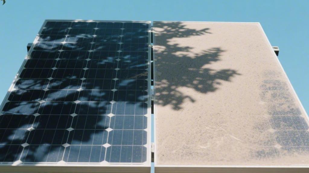
What are Factors Affecting PV Cell Output | Shading, Dust and Heat Issues
Partial shading can cause power to plummet by more than 50%;
Long-term dust accumulation leads to a 15% drop in conversion efficiency, and power typically degrades by 0.4% for every 1°C increase in ambient temperature.
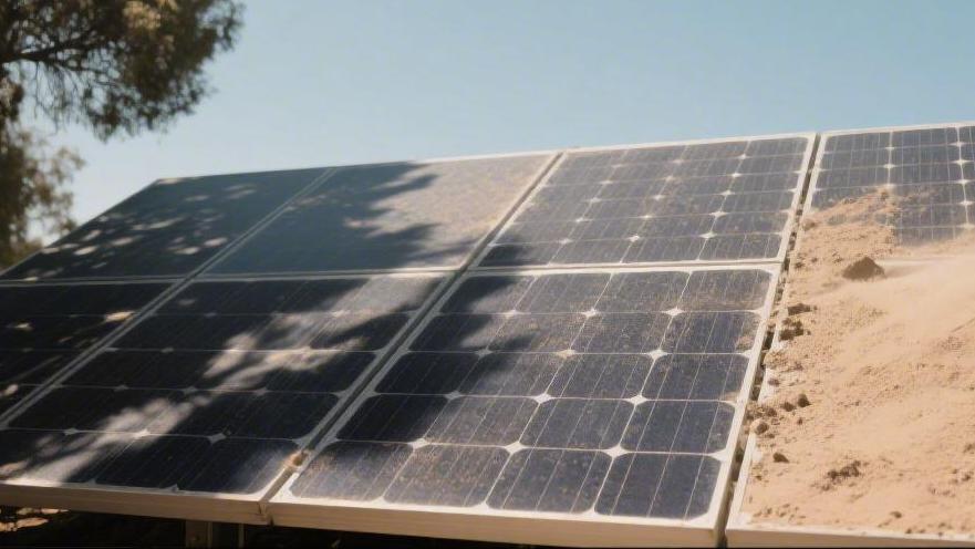
Shading
When just 10% of the surface area is shaded, the system's energy output can decrease by more than 30%.
Simultaneously, shaded solar cells transition from power sources into energy consumers.
Local junction temperatures can soar to 100°C–150°C within seconds, causing physical damage to the backsheet due to high heat and reducing the module's lifespan by more than 15 years.
External Sources of Shadows
A breather pipe with a height of 0.5 meters will produce a horizontal shadow approximately 0.86 meters long at noon on the Winter Solstice, when the solar altitude angle is 30 degrees.
If this long, narrow shadow crosses the long edge of the module—even if it is only 5 cm wide—it will cut off the current path for the entire string of cells, causing the module's output power to instantly drop by more than 80%.
In regions at 40°N latitude, to avoid the long shadows cast by parapet walls during early morning and late evening, a clearance of 3 times the wall height is typically required between the module array and the wall.
If a wall is 1.2 meters high, the area within 3.6 meters will essentially remain in a low-efficiency production state during winter.
Additionally, satellite receivers or outdoor air conditioning units installed on the roof generate irregular shadows.
These obstructions move with the seasons, increasing the frequency of Maximum Power Point Tracking (MPPT) adjustments by the inverter, which results in an additional 3% to 5% loss in system conversion efficiency.
Building Structure Type | Typical Dimensions | Shadow Coverage Characteristics | Quantitative Output Impact |
Standard Chimney | 0.6m wide, 1m high | Fan-shaped sweep following solar azimuth | Single string power drop of 60% to 90% |
Roof Vent Pipe | 0.1m diameter, 0.4m high | Narrow "hard shading" strip | Likely to induce 120°C local cell temperature rise |
Parapet Wall | 0.8m to 1.5m high | Large-area elongated shading | Reduces effective generation time by 1.5 hours |
AC Outdoor Unit | Occupies 1.2 m² space | Fixed block-shaped shadow | Local voltage fluctuations increase inverter restarts |
A broadleaf tree growing on the south side of the array can produce dark shadows with light transmittance of less than 10% when the leaves are lush in summer.
Research data shows that the growth rate of oak or maple trees is typically 30 to 60 cm per year.
If the top of the tree is only two meters from the edge of the module at initial installation, the tree will become a permanent shading source within 3 to 5 years.
Coniferous forests, such as pine, are evergreen, but their needle-like leaves create dappled shadows that cause frequent current mismatches within the cells.
This mismatch not only reduces energy output but also keeps the shaded cells in a reverse bias state at temperatures above 80°C for long periods, accelerating the yellowing of the EVA encapsulation material.
In windy areas, swaying branches create high-frequency flickering shadows.
This places extreme demands on the inverter's MPPT algorithm; if the response time exceeds 10 seconds, the system will lose approximately 2% of dynamic power generation revenue.
For distributed power stations located by the street, nearby utility poles and high-voltage lines cast very thin but deep shadows.
A utility pole with a 10 cm diameter located 5 meters from the module casts a shadow sufficient to cover an entire solar cell.
Due to the poor parallel characteristics of cells, this "linear shadow" can produce an effect similar to an open circuit.
In snowy winter regions, snow that has not slid off in time accumulates at the bottom edge of the module, forming an obstruction 5 to 10 cm thick.
This accumulation not only blocks light completely but also causes severe temperature differences between the top and bottom of the module, reaching up to 30°C. This thermal stress is a primary cause of micro-cracks in silicon wafers.
Env. & Infrastructure | Physical Characteristics | Light Transmittance Data | Electrical Consequences |
Broadleaf Tree (Summer) | Irregular large-area shading | Below 5% | Bypass diode forced on; voltage drop |
High-Voltage Line | 0.02m wide linear shadow | 30% to 50% (diffraction effect) | Local hot spots; lifespan shortened by 5 yrs |
Winter Snow Accumulation | Bottom 10-20% of module area | 0% (Opaque) | Causes whole string current to drop by 50%+ |
Nearby Antenna | Thin metal rod shadow | 10% to 20% | High-frequency small current perturbations |
In stations near industrial zones or traffic arteries, suspended particulate matter in the air accumulates on the surface to form a dust layer.
Although individual dust particles are tiny, when the accumulation reaches 10 grams per square meter, the shading effect is equivalent to covering the module with a semi-transparent film, causing irradiance to drop by more than 15%.
Even more serious are bird droppings. While the shaded area is small, because they are completely opaque and corrosive, they form high-density point-like shading.
Experiments show that a 3 cm diameter bird dropping under intense sun can cause the cell temperature at that spot to soar to 140°C within 5 minutes, far exceeding the tolerance limit of backsheet materials and leading directly to physical puncture.
This uncertainty in shading caused by biological activity is the primary external cause of burnout risk during a module's lifecycle.
When planning power station designs, professional software must be used to simulate the 8760-hour shadow movement trajectory of the year.
Due to the change in solar altitude angle caused by the Earth's revolution, an area that does not produce shadows at noon in summer may be in shadow for more than 50% of the time in winter.
For example, in high-latitude regions of the Northern Hemisphere, the shadow length on the Winter Solstice is more than 3 times that of the Summer Solstice.
If the array layout is too compact, front-row modules will self-shade the back row.
This usually occurs between 10 AM and 2 PM, when light intensity is most effective, causing an irreversible loss of 10% to 15% of the total annual power generation.
The "Barrel Effect" of Current
Under standard test conditions, the short-circuit current of monocrystalline silicon cells typically ranges from 10 to 13 Amperes.
When one cell encounters partial shading, the number of photo-generated carriers inside drops significantly, causing the equivalent impedance of that area to rise rapidly.
According to Kirchhoff's Current Law, the current intensity must remain consistent throughout a series circuit.
Therefore, the current output of the entire module string is forced to down-regulate to the maximum limit that the shaded cell can handle.
Even if the other 71 cells are under full irradiation and could generate 11 Amps, if just one cell can only produce 3 Amps due to leaf shading, the output of the entire circuit will instantly lock at around 3 Amps.
Experimental records show that when only 5% of a module's light-receiving area is uniformly shaded, the total power output often suffers a massive attenuation of 25% to 40% due to the current bottleneck.
In large-scale ground stations in North America, inverters must perform MPPT on hundreds of connected module strings.
When a current bottleneck appears in a string, the output voltage and current curve (I-V curve) deforms drastically, creating multiple local power peaks.
This makes it extremely difficult for standard inverter algorithms to locate the optimal operating point.
· Flow Output Decline: If a single cell's current drops to 2A, the total current for a string of 20 modules drops to 2A, resulting in power losses of up to 80%.
· Voltage Shift Phenomenon: To compensate for the current deficit, the system sometimes increases operating voltage, but this moves the efficiency away from the high-performance range, wasting energy as heat.
· Fill Factor Deterioration: Shading-induced current unevenness causes the Fill Factor (FF) to drop from a standard 0.78 to below 0.5, severely weakening the cell's energy conversion quality.
· Internal Shunt Resistance Variation: Because the PN junction of the shaded cell cannot open normally, its shunt resistance (Rsh) exhibits extremely high values, becoming a physical barrier to current flow.
Under normal operation, cells convert absorbed light into electricity and output it to the load.
However, when current flow hits a bottleneck caused by the barrel effect, the shaded cell no longer works as a power source but turns into a power-consuming load.
Since the current generated by other normal cells in the string still tries to pass through this area, this energy is converted into heat in the high-impedance shaded zone.
Observations in mountain stations in Europe found that this thermal effect can push the surface temperature of shaded cells to 80°C or even 110°C within minutes.
Long-term thermal stress leads to irreversible chemical degradation of the EVA encapsulation material, decreasing light transmittance and exacerbating the negative cycle caused by shading.
This temperature rise also causes fine physical cracks within the silicon wafer. Once a crack penetrates the entire cell, the resistance there will be permanently elevated; even if the shading is removed, the module current output cannot return to its rated state.
Current Limitation Metric | Normal State | Partial Shading State | Performance Change |
Single Cell Output Current | 10.5 A to 11.2 A | 1.5 A to 2.8 A | 75%+ Decrease |
Series Circuit Total Output | 5,500 Watts (Sample String) | 1,200 Watts (1 cell shaded) | 78% Power Loss |
Local Cell Junction Temp | 45°C to 55°C | 95°C to 145°C | 100%+ Temp Rise |
Reverse Bias Voltage | 0 Volts (Ideal) | -12 V to -20 V | Severe potential loss |
While bypass diodes protect modules from burning out, their activation cuts off the voltage output of that sub-string.
For example, in a 72-cell module, if one 24-cell sub-string triggers diode conduction due to a single shaded cell, the module's voltage will immediately drop by one-third.
In residential rooftop projects, these frequent jumps caused by current bottlenecks lead to additional switching losses in the inverter's power modules, shortening the lifespan of electronic parts.
Researchers have found that modules using half-cut cell technology perform better against elongated shadows.
The half-cut design splits the internal current into two parallel paths; even if one path hits a bottleneck, the other can maintain 50% of the rated current, halving the overall system power loss.
In dry and dusty regions, annual generation loss due to current mismatch often accounts for about 12% of total losses.
To combat this, modern designs are increasingly adopting module-level monitoring systems.
These systems detect current fluctuations in every string. If one area's current is 15% lower than the average, background algorithms immediately identify physical shading or soiling risks.
By installing Module-Level Power Electronics (MLPE) such as DC power optimizers, independent regulation of each module's voltage is possible.
When a module's current decreases due to the barrel effect, the optimizer lowers the voltage and boosts the current to match the rest of the string, ensuring unshaded modules still work at 100% efficiency, recovering 15% to 25% of potential energy loss.
Bypass Diode Mechanism
In a standard 72-cell module, the internal circuit is divided into three units, each containing 24 cells in series.
When irradiation is uniform, these diodes are in a reverse-biased cutoff state and consume no power.
Once a single cell in a sub-string is shaded, its equivalent resistance skyrockets from milliohms to thousands of ohms, blocking the string's current.
At this point, the voltage drop produced by that sub-string causes the potential difference across the parallel diode to flip, forcing the diode from cutoff to forward conduction.
When the external current is 13 A, it bypasses the blocked cell sub-string, flowing through the low-resistance path provided by the diode. This mechanism protects the shaded cell from being burned by the forced current, but the cost is that the 24 cells in that sub-string stop generating power.
Under normal operation, a sub-string works at about 12V to 15V.
Once the bypass diode conducts, the output voltage of that sub-string drops to approximately -0.4V to -0.7V, depending on the forward voltage drop of the Schottky diode used.
For the whole module, this results in an instantaneous loss of about one-third of total output voltage.
In high-voltage systems (like 1000V or 1500V systems), this voltage drop forces the MPPT system to rescan the I-V curve.
During scanning, the curve will show multiple local peaks. If the algorithm is inefficient, the system might lock onto a low-voltage local power point, causing extra energy loss.
Schottky diodes generate continuous heat in the conduction state. With a 10 A string current and a 0.45 V forward drop, a single diode produces 4.5 watts of heat.
On a summer noon with an ambient temperature of 40°C, the junction temperature of a conducting diode can climb to 125°C or higher in a short time.
If the shading fluctuates frequently, the diode undergoes cycles of conduction and cutoff, leading to mechanical fatigue at the solder points.
In long-term monitoring data (10+ years), bypass diode failure is a leading cause of junction box destruction.
Failure modes are split into open-circuit and short-circuit failures. A short-circuit failure causes the sub-string to exit generation permanently, losing 33%+ of module power;
An open-circuit failure is the most dangerous, as the bypass mechanism is lost, forcing current through high-impedance shaded cells and inducing extreme temperatures exceeding 150°C.
In residential rooftop projects, tree shadows move with the sun. When a shadow covers a single cell on the edge, bypass diode intervention can recover about 60% of the theoretical energy loss, preventing the entire module string from stopping.
It is typically required that the diode's rated current be at least 1.5 times the module's short-circuit current (Isc) to handle over-current from sudden irradiation bursts.
In high-performance modules, to further reduce heat loss during conduction, researchers have introduced active bypass switch technology, using MOSFETs instead of traditional Schottky diodes.
The forward voltage drop of these active switches is less than 0.1 V, reducing heat loss by over 80% and significantly extending the lifespan of junction boxes in complex shading environments.
However, the material cost is higher, so it is primarily used in high-end commercial or specialized projects requiring extreme reliability.
Shading impacts on sub-strings have a trigger threshold. Research shows that when the shaded area of a single cell exceeds 15%, the internal resistance increases to the voltage condition to trigger diode conduction.
For a string of 20 modules, one module's diode conducting drops the string voltage from ~800V to 785V.
If shadows cover multiple modules simultaneously, the total voltage might drop below the inverter's minimum operating range.
By using a more detailed sub-string layout—such as installing modules horizontally instead of vertically—long linear shadows on the ground may only trigger one diode's protection, preserving the generation of the other two sub-strings and minimizing output loss.
In cases of partial winter snow coverage at the bottom of modules, horizontally installed modules using bypass diodes can maintain 66.7% power output, whereas vertical installation might result in zero output.
In coastal areas with heavy salt spray or high-humidity rainforests, sealing failure in junction boxes allows moisture in, causing diode pin oxidation.
The increased contact resistance from oxidation worsens heat loss, creating a vicious cycle that eventually leads to junction box fires or backsheet burn-through.
Therefore, in overseas O&M standards, regular thermal imaging scans of junction box temperature distribution are a standard procedure.
If a junction box shows abnormal temperature rise under full sun, it usually indicates the internal diode is in an abnormal state of conduction or aging and needs immediate replacement.
Dust
In arid regions like California or the UAE, generation loss from two weeks without cleaning is typically between 5% and 10%.
When surface dust density reaches 5 g/m², the short-circuit current (Isc) of the photovoltaic cell drops by approximately 20%.
Compared to 10µm coarse dust, 2µm fine particles have a more significant shielding effect on the blue light portion of the spectrum, directly limiting the photoelectric conversion ceiling.
Surface Optical Changes
The glass cover of PV modules typically has a refractive index of around 1.5 and is coated with an Anti-Reflective Coating (ARC) about 100 nm thick to increase light transmittance.
When external dust accumulates on the glass, the originally flat optical interface evolves into a complex non-homogeneous layer of air, dust particles, and glass.
This change is first reflected in the reflection behavior of incident light at the interface, shifting from regular specular reflection to diffuse diffuse reflection.
According to data from Nevada deserts, when dust density increases from 0 g/m² to 2.5 g/m², the hemispherical reflectance of the module surface rises from about 4% to over 12%.
This increase in reflectance corresponds directly to a reduction in photons entering the cell. The physical size distribution of dust particles plays a decisive role in optical changes.
Fine particles between 0.5 µm and 5 µm generate strong Mie scattering because their cross-sectional area is close to the wavelength of high-energy bands in the solar spectrum.
This scattering not only changes the direction of light, extending its path inside the cover, but also increases the probability of light being absorbed or reflected back to the atmosphere before reaching the silicon wafer.
Research indicates that at the same mass concentration, 2µm particles reduce light transmittance three times more than 10µm particles.
This optical change is wavelength-selective; the dust layer attenuates short-wave light (300 nm–600 nm, like blue and UV) much more than infrared light (1000 nm).
Dust Density (g/m²) | 400nm Transmittance (%) | 700nm Transmittance (%) | 1000nm Transmittance (%) |
0.0 (Clean) | 91.5 | 92.2 | 90.8 |
1.0 | 85.3 | 88.6 | 89.1 |
3.0 | 72.4 | 78.9 | 81.5 |
5.0 | 60.1 | 68.4 | 72.3 |
10.0 | 42.6 | 51.5 | 58.7 |
For much of the day, PV modules are not directly facing the sun, meaning the Angle of Incidence (AOI) is often greater than 45 degrees.
For clean glass, the Incidence Angle Modifier (IAM) follows Fresnel's Law, but under dusty conditions, the rough particle layer significantly increases the reflection loss of oblique light.
Experiments in Saudi Arabia found that when the AOI reaches 60 degrees, a moderately dusty module (3 g/m²) suffers an additional 8% to 12% power loss compared to noon.
AOI (Degrees) | Clean Transmittance Drop (%) | Dusty (2 g/m²) Transmittance Drop (%) | Extra Optical Deviation |
0 (Vertical) | 0.0 | 6.5 | 6.5 |
30 | 1.2 | 9.8 | 8.6 |
45 | 3.5 | 14.2 | 10.7 |
60 | 12.8 | 26.4 | 13.6 |
75 | 38.5 | 58.2 | 19.7 |
Dust particles constantly friction against the glass under wind, creating tiny scratches that permanently change the surface roughness (Ra).
Once Ra rises from nanometers to micrometers, anti-reflective properties are lost, and even after cleaning, transmittance cannot return to factory levels, resulting in 1% to 2% irreversible light loss.
In coastal high-humidity areas, salt spray combined with dust can undergo deliquescence, forming an acidic or alkaline electrolyte film.
A long-term study in Frankfurt showed that without maintenance, PV glass haze in industrial environments can rise by 1.5% in 5 years.
Particle Type Differences
In natural environments, mineral dust is the most common pollutant.
For example, particles from the Sahara or Arabian Peninsula are mainly silica, alumina, and calcium carbonate, with PM10 particles being the most persistent.
If mineral dust contains high levels of iron oxide, power attenuation is about 15% higher than pure silica because iron strongly absorbs short wavelengths.
This darker dust also increases module temperature by 2–3°C at noon, further lowering efficiency.
Particle Type | Main Chemistry | Avg. Size (µm) | Absorp. Term | Power Loss @ 1 g/m² |
Desert Dust | SiO2, Al2O3, CaCO3 | 5 - 50 | Low | 3.5% - 5.2% |
Industrial Soot | Elemental/Organic Carbon | 0.1 - 2 | High | 12.8% - 15.5% |
Coastal Salt | NaCl, MgCl2 | 1 - 10 | Very Low | 2.1% - 4.5% |
Pollen | Cellulose, Protein | 10 - 100 | Medium | 4.8% - 7.6% |
Urban Dust | Silicates, Sulfates | 2 - 20 | Medium | 6.2% - 8.9% |
In urban/industrial zones, soot from traffic/emissions is extremely destructive.
These sub-micron particles (0.1 µm–0.5 µm) have very high extinction coefficients. Even a very thin layer can cause significant energy dissipation.
Biological particles like pollen and bird droppings show high adhesion. Bird droppings contain uric acid and phosphates, causing intense chemical reactions and complete local shading.
Under thermal imaging, these areas can exceed 80°C, leading to EVA yellowing or backsheet embrittlement.
Pollutant Source | Adhesion Level | Cleaning Difficulty | Typical Chemistry | Glass Impact |
Construction Cement | Extreme | 5 (Hardest) | Strongly Alkaline | Permanent Corrosion |
Traffic Exhaust | High | 4 | Oily, Hydrophobic | Hard-to-wash Oil Film |
Desert Sand | Low | 1 (Easy) | Dry, Physical | Abrasive wear |
Coastal Salt | Medium | 3 | Deliquescent | Triggers PID/Corrosion |
When humidity exceeds the deliquescence point (75%), solid salt turns to liquid droplets.
These spread over the glass, increasing optical loss and leakage current risk, often triggering inverter insulation protection shutdowns.
Tilt and Gravity Influence
On a horizontal (0°) system, gravity acts vertically, increasing the pressure of dust against the ARC. In the Atacama Desert, horizontal modules had 60% more dust than those at a 30° tilt after 30 rainless days.
In a year-long Nevada test, 15° tilt modules accumulated 5.8 mg/m² daily, while 45° tilt modules accumulated only 2.1 mg/m². This kept 45° modules at 94% efficiency vs 86% for low-tilt modules.
Low tilts (under 5°) on flat roofs limit self-cleaning. Morning dew or light rain carries dust to the bottom edge.
Because the tilt is too small, gravity cannot overcome the surface tension of the aluminum frame, leaving a 2mm–5mm thick mud strip.
This "edge damming" can reduce annual generation by over 10%.
Comparative data for 5°, 10°, and 20° tilts showed 5° modules lost 4 times more power after light rain than 20° modules. High tilts allow water to reach speeds of 0.5 m/s, enough to carry away particles.
In high-latitude regions like Central Europe, modules are often at 40–50 tilt for winter sun, which inadvertently alleviates dust pressure.
Gravity's sliding force at these angles is close to the static friction of dust on glass.
In Queensland, Australia, sand grains >100 µm slid off at 30° tilts with a 3 m/s wind, while particles <20 µm stayed attached even at 10 m/s wind because van der Waals forces exceed the gravity module.
Heat Issues
Output power typically drops by 0.3% to 0.48% for every 1 degree above 25°C.
When the ambient temperature reaches 35°C, internal cell temperatures often exceed 65°C, causing actual output to be 12% lower than the rated power.
N-type cell technology can control the temperature coefficient to within -0.3% per degree, providing a 3% to 4% generation gain over traditional P-type modules in the same heat.
Output Power Decline
Under STC (25°C), modules are at their peak. In the field, they absorb infrared radiation and heat up.
For P-type modules, the coefficient is -0.35% to -0.45%/C. In Texas or the Sahara, summer noon temperatures of 70°C (+45°C over STC) cause power losses of 15.7% to 20.2%.
Voltage drop is the primary cause. Semiconductor bandgap narrows as temperature rises:
· Open Circuit Voltage (Voc) Drop: Voc drops by ~2.0 to 2.2 mV per 1°C. At a 45°C difference, a single cell drops nearly 0.1 V.
· Insufficient ISC Compensation: While ISC grows by ~0.04% to 0.06%/C, it cannot offset the massive voltage drop.
· Fill Factor (FF) Deterioration: High heat increases carrier recombination and ohmic losses in grid lines, rounding the I-V curve and adding 1% to 2% more loss.
Technology Type | Typical Temp. Coeff. (Pmax) | Power Drop @ Δ50°C | Characteristics |
P-type Mono PERC | -0.38% / °C | 19.0% | Traditional; most sensitive to heat |
N-type TOPCon | -0.30% / °C | 15.0% | Passivated contacts reduce heat loss |
N-type HJT | -0.26% / °C | 13.0% | Symmetric structure; best heat performance |
Thin Film CIGS | -0.23% / °C | 11.5% | Low thermal sensitivity |
If voltage falls below the inverter's MPPT threshold, efficiency plummets.
Embedded roof installs without ventilation can be 15–20°C hotter than rack-mounted ones, causing an extra 4% annual loss.
· Wind Speed: In the Atacama, a 3.5 m/s wind keeps modules 20°C above ambient; in stagnant Southeast Asia, it can reach 35°C above ambient.
· Convection: Tilts >20° gain from the "chimney effect." Flat commercial roof mounts create dead zones, adding 5–8°C of heat.
· Cabling: Resistance in copper cables rises by 16% for every 40°C increase, adding ~0.5% loss in large plants.
Mechanism of Efficiency Loss
Silicon bandgap is not constant; it shrinks as temperature rises. At 25°C, it's 1.12 eV. As atoms vibrate more with heat, the gap narrows, allowing more low-energy photons to be absorbed (slight ISC gain) but causing massive voltage loss.
Microscopically, heat speeds up carrier movement, increasing collisions with impurities and shortening "minority carrier lifetime." At 60°C, recombination is several times higher than at 25°C.
Only ~20% of radiation becomes electricity; 80% becomes heat. If air speed is <1 m/s, heat accumulation creates an extra 5°C rise.
In North Africa, daily ΔT of 30°C can make annual yields 6% lower than predicted if inverters lack a wide input voltage range.
Long-term Hardware Damage
Tempered glass expands at 0.000009/°C, while silicon expands at 0.0000026/°C. This 4x difference creates constant stress in desert environments with huge day/night swings.
Thermal expansion/contraction creates shear forces that destroy passivation layers. 200 cycles of thermal shock can make power degradation 1.5%–3% higher than normal.
Above 60°C with UV, EVA releases acetic acid. This corrodes silver grid lines and tin solder, forming silver/tin acetate.
Acetic acid corrosion turns grid lines black and increases resistance. A 3000-hour damp heat test (DH85) showed that at 80°C+, encapsulation yellowing reduces photons by 2%–4%.
Solder fatigue is a major heat loss source. Grains coarsen twice as fast for every 10°C rise, leading to micro-cracks and reduced conductivity.
High heat reduces glass surface resistance, promoting sodium ion migration from glass to cell.
In high-heat/high-humidity areas like Abu Dhabi, PID effects can cause 20% power loss in just three years.