Why Buy Small Solar Modules | 3 Factors You Must Consider
Prioritizing products with conversion rates exceeding 21% and IP67 protection ratings is essential.
Such modules can operate stably for over 15 years in 50W off-grid scenarios, serving as a core detail for ensuring continuous power supply and enhancing long-term return on investment.
Portability and Form Factor
Small-scale solar modules typically control their weight between 450 g and 1.8 kg.
When folded, the thickness is often less than 25 mm, with a volume equivalent to an A4 magazine—reducing the size by more than 70% compared to fixed panels of the same power.
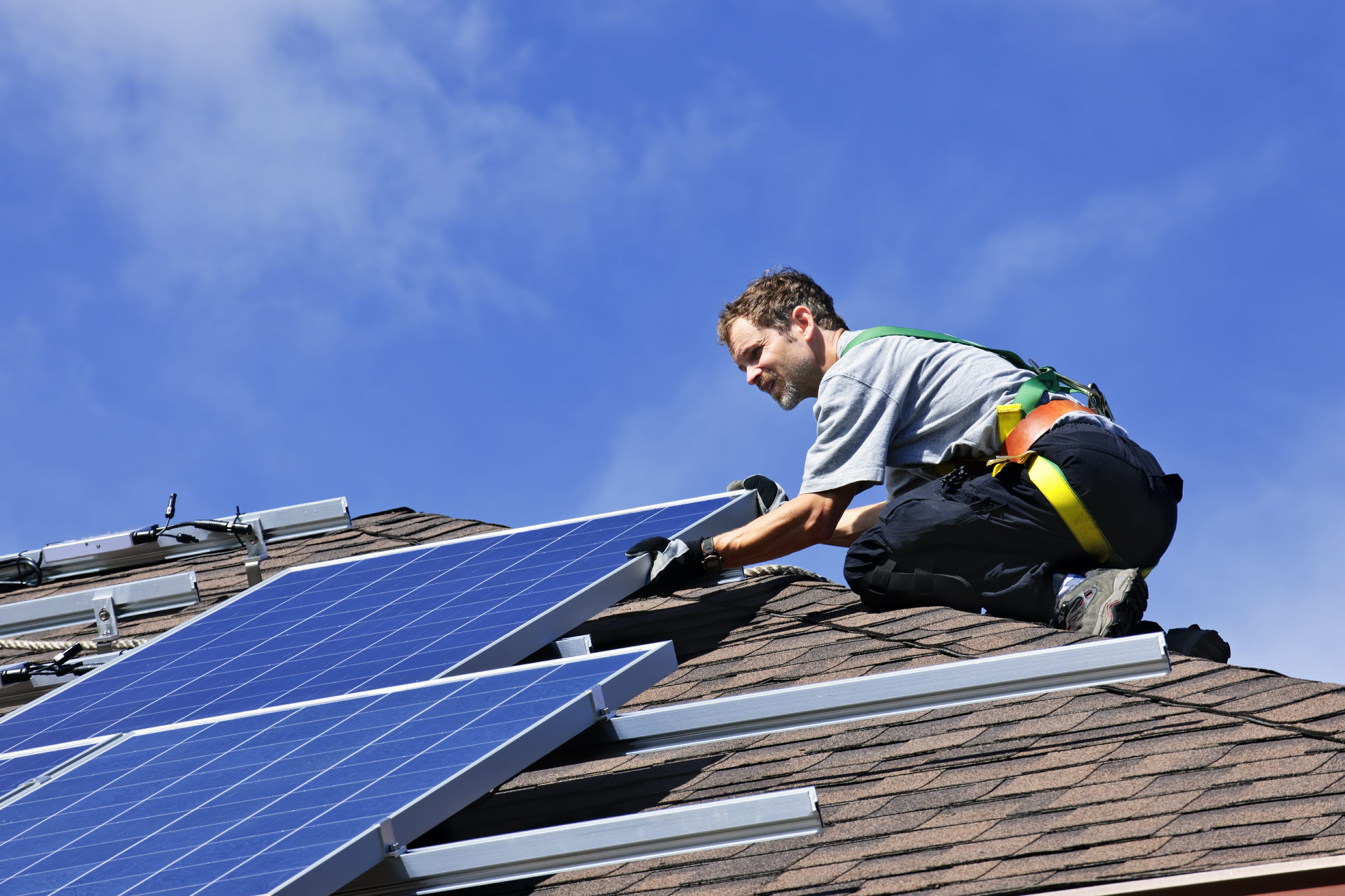
These modules mostly adopt a tri-fold or quad-fold layout, with 5mm diameter stainless steel hanging holes distributed along the edges to fit standard D-type carabiners.
Through the ETFE full-lamination process, the thickness of a single sheet can be compressed to 2 mm, allowing it to fit directly into the compartment of a 20 L hiking backpack.
Material & Weight Control
High-end mobile modules have now widely abandoned 3.2 mm thick tempered glass in favor of ETFE (Ethylene Tetrafluoroethylene) as the light-transmitting encapsulation layer.
The density of this fluoropolymer film is only 1.7 g/cm³, whereas the density of traditional glass is as high as 2.5 g/cm³.
By using ETFE films with thicknesses of 0.025 mm to 0.05 mm, the weight load of the module's top layer can plummet from 8 kg per square meter to 0.15 kg.
ETFE material possesses a light transmittance of over 95% and features a unique honeycomb-like convex structure.
This design captures sunlight at larger angles of incidence through multiple refractions, increasing power generation efficiency by about 5% during early morning or evening hours.
In contrast, PET (Polyethylene Terephthalate) films used in cheap modules exhibit significant yellowing and peeling after 12 months of UV exposure, with transmittance dropping below 80%, leading to a power degradation rate of 10% per year.
High-performance portable modules typically use FR-4 fiberglass boards or flexible PCBs (Printed Circuit Boards) as a substrate instead of heavy aluminum alloy frames.
A 1.2mm thick FR-4 backplane not only provides enough rigidity to resist 2400Pa of wind pressure but also keeps the overall module thickness within 3mm.
For hikers pursuing extreme light weighting, an all-black fiberglass-reinforced resin board with a thickness of only 0.5 mm can reduce the weight of a 21W charging board to around 450 g, which is only equivalent to a 500 ml bottle of mineral water.
The table below compares weight distribution and physical parameters under different material combinations:
Module Name | Material Type | Typical Thickness (mm) | Unit Weight (g/㎡) | Technical Characteristics |
Transparent Protective Layer | Imported ETFE Film | 0.05 | 85 | UV resistant, self-cleaning, salt spray resistant |
Cell Encapsulant | High-transmittance EVA | 0.45 | 420 | Bonding strength > 40 N/cm |
Back sheet Substrate | Epoxy Fiberglass Board | 1.0 | 1850 | Insulation voltage > 1000 V |
Circuit Wiring | Tinned Copper Ribbon | 0.12 | 120 | Resistivity < 0.017 Ω·mm²/m |
Outer Jacket | 1200D Oxford Fabric | 0.8 | 650 | Hydrophobic coating, wear-resistant |
In small modules under 100 W, a single set of traditional MC4 connectors weighs about 25 g, which, combined with 4 mm² PV DC cables (weighing about 70 g per meter), significantly increases the carrying burden.
Modern designs tend to integrate miniature junction boxes with thicknesses of less than 10 mm, outputting DC 5521 or USB current directly through 14 AWG or 16 AWG soft silicone wires.
This weight reduction, combined with SunPower Maxeon shingled technology, eliminates metal bus bars on the cell surface. This not only increases the light-receiving area by 10%, but also reduces physical thickness caused by ribbon stacking.
A 100W quad-fold module using the high-specification materials mentioned above has a total unfolded area of about 0.55㎡, with the weight precisely controlled between 2.1 kg and 2.4 kg, while rigid aluminum frame panels of the same power usually weigh over 7.5 kg.
Environmental adaptability data shows that the ETFE encapsulation layer has a physical deformation of less than 0.1% under extreme temperature cycles from -20°C to 80°C.
This stability is vital for modules fixed to the roof of a Sprinter camper van or the outside of an Osprey hiking pack, as it prevents silicon wafer micro-cracks caused by thermal expansion and contraction.
The Multi-Busbar (MBB) technology used at cell connections employs fine circular copper wires with a diameter of only 0.1 mm. Compared to traditional flat ribbons, it reduces the shading of active materials and exhibits stronger mechanical toughness in bending tests.
Hanging holes at the edges of the module are usually embedded with 304 stainless steel rings with an inner diameter of 8 mm.
The tensile strength of a single mounting point can reach over 50 kg, ensuring mounting safety in high-wind environments.
For users who prioritize space utilization, thickness control and weight control follow a parallel logic.
When the module is folded, the friction between layers is handled by wear-resistant nylon fabric of 1000D specification or higher.
This fabric weighs about 350 g to 450 g per square meter and possesses a protection rating of IP65 or even IP67.
In actual weighing tests, a complete 60W system including brackets, cables, and storage bags can have its total weight controlled at around 1.8 kg if an ultra-lightweight solution is selected.
Compared to earlier products using heavy canvas and thick PET films, the weight is reduced by about 40%, but the expected service life has been extended from 24 months to over 60 months.
The chemical inertness of the materials also allows these modules to resist bird droppings, corrosion, and acid rain erosion, maintaining stable photoelectric conversion output without the need for frequent cleaning.
Storage Volume Comparison
A standard mobile module with a rated power of 21W to 28W typically has a light-receiving area of 0.12 to 0.15 square meters when unfolded.
Through structural optimization of tri-fold or quad-fold designs, its closed planar projection area is only about 280 x 160 mm.
This area compression ratio of over 75% allows equipment that would otherwise occupy external backpack space to fit smoothly into the laptop compartment of a 20-liter hiking pack.
The stored thickness is generally controlled between 15 mm and 30 mm. Magnetic buckle designs replace traditional thick plastic clips, compressing the stacking gap between layers to within 2 mm.
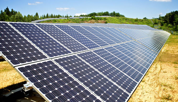
High-power folding panels in the 100W class show even more prominent technical performance in volume optimization.
Compared to a single 100W rigid aluminum frame panel, a four-fold or six-fold portable module of the same power measures only 400 x 350 x 45 mm when closed, reducing the physical volume to approximately 6.3 liters.
This 64% reduction in physical volume frees up a significant amount of locker space for the "Van Life" community.
· 20L Urban Hiking Pack Side Pocket: Fits single-panel modules under 14W; storage thickness 10mm; does not occupy main bag space.
· 65L Professional Trekking Pack Main Compartment: Fits multi-fold modules from 60W to 100W; vertical width occupancy under 50mm.
· Camper Van Passenger Glove Box: Can horizontally store two sets of 100W folding arrays; total depth occupancy under 10 cm.
· Standard 20-inch Carry-on Suitcase: Complies with ICAO size recommendations for carry-on luggage; can carry three to five 40W modules without affecting other clothing.
Modern designs integrate USB output ports and DC terminals into an 8mm thick injection-molded box, which is embedded into pre-designed recesses on the surface of the folded layers.
When the module is completely closed, the junction box does not protrude from the surface, avoiding additional physical stress in the stacked state.
This flat surface treatment ensures that in off-grid office scenarios, multiple panels can be arranged vertically on a storage rack like books.
The folding axis of the module uses high-frequency heat pressing technology, with the axis width precisely set at 5 mm.
This not only reserves space for 0.15 mm thick flexible flat cables for internal cross-panel wiring but also ensures mechanical fatigue strength after multiple openings and closings.
In experiments targeting 5,000 reciprocal folds, this structure maintained a circuit conduction rate of 99.8%.
In the closed state, this axis structure keeps the cells of each layer aligned in parallel, eliminating internal silicon wafer damage caused by uneven pressure.
Because of their length of over one meter, 100W rigid panels are often classified as oversized items by logistics companies, incurring additional surcharges.
In contrast, the total perimeter of a folded 100W module is usually less than 90 cm, allowing it to fit into standard-sized shipping cartons.
For the digital nomad community, this volume advantage allows users to fit a laptop, power bank, and a 40W solar module into a 15-inch laptop bag simultaneously, with a total thickness increase of no more than 2 cm.
The 1200D nylon fabric selected for the module casing ensures wear resistance while keeping the thickness at 0.8 mm through heat pressing.
Compared to earlier products using heavy canvas, the single-layer thickness is reduced by 30%. In cold environments, the physical flexibility of this polymer material remains stable, preventing the folded volume from expanding due to low-temperature hardening.
For field research missions requiring multiple sets of panels, the reduction in volume and weight makes it possible for a single person to carry a system with a total power of 300W to 500W.
Mounting Layout Optimization
Standard mobile modules of 21W to 100W typically distribute 4 to 8 reinforced circular holes along their perimeter.
These holes are embedded with 304 stainless steel rings, with a standardized inner diameter of 8 mm.
This aperture specification is designed to precisely fit internationally common D-type carabiners and 550-spec paracord.
Tensile strength test data for each load-bearing point usually exceeds 50 kg, ensuring that the module will not physically tear when encountering strong winds over Level 8 or violent shaking during external vehicle mounting.
The positioning of these holes is calculated geometrically, with the center of the hole usually maintained at 15 mm from the edge to maximize the dispersion of tensile stress.
For adaptation to professional hiking packs over 50L like Osprey or Gregory, the aspect ratio of the module coincides with the height of the pack's daisy chain, allowing for stable center-of-gravity distribution through 4-point positioning to prevent swaying during walking.
In actual deployment, the compatibility of the mounting system determines energy collection efficiency. For example, using a 5mm diameter elastic shock cord through the 8mm holes at the four corners can quickly tension the module onto the top of an MSR or Big Agnes hiking tent.
The physical layout of the module also considers interaction with hard surfaces. For RV or long-distance sailing users, flat areas are typically reserved at the bottom of the module for industrial-grade suction cup adaptation.
By installing 50 mm diameter vacuum suction cups at the four corners, the module can be firmly attached to a Tesla shell or the fiberglass deck of a yacht.
This layout utilizes the 30-degree flexible bending characteristic of the ETFE encapsulation layer, allowing the panel to conform to curved roofs, reducing aerodynamic resistance at high speeds.
To prevent metal hooks from scratching the encapsulation layer, the holes are usually surrounded by 1.5 mm thick ultrasonic-welded Hypalon.
This material maintains physical toughness in environments from -40°C to 80°C without brittle fracture.
The specifications for mounting accessories are as follows: a standard D-type buckle weighs approx. 12 g with a static load of 20 kg; a single industrial vacuum suction cup has a suction force of 5 kg; a 5 mm diameter nylon pull rope has a tensile strength of approx. 240 kg per meter. The coordination of these accessories with the 8mm holes constitutes the physical foundation of the mobile energy system.
The routing of internal circuit wiring is co-designed with the external mounting layout.
To avoid physical compression damage to cells during mounting, multi-strand tinned copper foil ribbon cables connecting the solar wafers are hidden inside a 5mm thick reinforced edge binding.
This binding is made of 1200D ripstop nylon and is integrated with the substrate through high-frequency heat pressing.
The junction box layout is usually biased toward the top side and uses a countersunk embedded design with a height of no more than 10 mm.
This layout ensures that when the module is hung vertically behind a backpack via the top two holes, the output cable can enter the bag to connect to a power bank naturally, avoiding a 90-degree mechanical bend at the interface and increasing the interface service life by about 3 times.
In static deployment scenarios, the mounting layout evolves into a support system.
Some high-end modules over 60W integrate hidden brackets on the back, with the bracket angle fixed at 45 degrees via Velcro—the empirical angle for obtaining the highest photoelectric conversion rate in mid-latitude regions globally.
The bracket material uses 1.2 mm thick fiberglass-reinforced plastic (GFRP), connected to the main panel by 25 mm wide nylon webbing.
This three-point support layout maintains stability on soft sand or uneven gravel, increasing power generation efficiency by about 20% compared to horizontal placement.
When the support function is not needed, the bracket folds completely flat within the rear nylon kit, with a total thickness increase of less than 3 mm.
Energy Conversion Efficiency
Current mainstream N-type monocrystalline silicon module commercial efficiency remains between 21.5% and 24.2%.
Under standard 1,000 W per square meter sunlight, high-efficiency modules produce over 25% more electricity than ordinary modules of the same size.
This significantly shortens the charging cycle of 12V 100Ah cell packs in space-constrained scenarios like RV roofs or remote monitoring, ensuring power continuity.
Cell Material Comparison
Monocrystalline silicon cells in the mainstream market are purified to 99.9999999% through the Siemens process. The crystal lattice is completely arranged, reducing recombination losses of electrons at grain boundaries.
N-type monocrystalline silicon is doped with phosphorus, effectively avoiding the boron-oxygen complexes common in P-type wafers.
Under standard test conditions, the open-circuit voltage of N-type TOPCon cells can reach over 700 mV, while ordinary P-type PERC cells are usually between 670 mV and 685 mV.
This voltage difference manifests as an earlier charging start time on small 20W to 50W modules.
In low-light environments (e.g., light intensity below 200 W/㎡), the relative efficiency of N-type cells is 10% to 15% higher than that of P-type cells.
Due to area constraints, small modules use 182 mm or 210 mm large-size wafer slicing technology to reduce the proportion of non-active areas.
Physical Attribute | Mono N-Type (TOPCon) | Mono P-Type (PERC) | Polycrystalline (Poly-Si) | CIGS Thin Film |
Carrier Lifetime | Over 1000 μs | 50 to 200 μs | 1 to 10 μs | 0.5 to 2 μs |
First-year Power Degradation | Approx. 1.0% | 2.0% to 2.5% | 2.5% to 3.0% | 3.0% to 5.0% |
Annual Degradation (25 yr) | 0.4% | 0.45% to 0.55% | 0.6% to 0.7% | 0.8% to 1.0% |
Spectral Response Range | 300nm to 1200nm | 300nm to 1100nm | 350nm to 1100nm | 400nm to 1300nm |
Absorber Layer Thickness | 130 to 150 μm | 150 to 170 μm | 170 to 190 μm | 1 to 3 μm |
Polycrystalline materials consist of a large number of randomly oriented tiny crystals. There are numerous dislocations and impurities at grain boundaries, leading to severe scattering of carriers as they pass through.
Although the manufacturing cost of polycrystalline silicon is about 15% to 20% lower than that of monocrystalline silicon, its power output per unit area is typically over 20% lower.
On a 100 cm x 60 cm mounting spot, using polycrystalline silicon only yields about 80 W of nominal power, whereas using high-efficiency monocrystalline silicon can reach over 110 W.
The temperature coefficient of polycrystalline silicon is usually around -0.4%/°C. When the ambient temperature rises above 40°C and the internal cell temperature reaches 65°C, the output power will drop by about 16%.
The structural advantage of monocrystalline silicon results in a smaller power drop under the same heat conditions, maintained between 12% and 13%.
For specific scenarios requiring lightweighting and flexibility, thin-film technologies such as CIGS (Copper Indium Gallium Selenide) and CdTe (Cadmium Telluride) provide different options.
CIGS is a ternary compound semiconductor with a light absorption coefficient as high as 10^5 per cm, requiring a film thickness of only about 2 microns to absorb over 99% of visible light.
This material responds better to the infrared part of the spectrum, with 10% to 20% higher power generation than crystalline silicon in early morning, evening, or cloudy weather.
Although CdTe is slightly less efficient than monocrystalline silicon, its bandgap width is 1.45 eV, which matches the solar spectrum extremely well, and its stability in high-temperature and humid environments is superior to traditional amorphous silicon thin films.
Amorphous silicon thin films are rarely used as a first choice in professional off-grid systems today due to severe Staebler-Wronski effects, where efficiency drops by over 20% in the first 1,000 hours of use.
· 166mm Wafer (M6): Often used for small rigid panels under 100W; production process is extremely stable.
· Shingled Technology: Cells are cut and stacked like tiles, eliminating the gaps of traditional ribbons and increasing the effective light-receiving area by about 13%.
· Half-cut Technology: Cells are cut in half to reduce internal operating current. Halving the current reduces internal Joule heat loss to one-fourth, increasing output power by 2% to 3%.
· PERC Passivation Technology: Adds an aluminum oxide passivation layer to the back of the cell to reflect unabsorbed photons back for secondary absorption, increasing conversion rates by about 1%.
Bifacial monocrystalline silicon modules are beginning to be popularized in small-scale applications.
If installed on a high-reflectivity surface (such as light-colored RV roofs or snow), the rear side can contribute 5% to 25% additional power.
In off-grid monitoring systems, using bifacial modules can effectively mitigate power gaps caused by low winter sun angles.
Furthermore, different materials have different resistance to the PID (Potential Induced Degradation) effect.
Monocrystalline modules encapsulated with POE (Polyolefin Elastomer) can maintain over 95% of their electrical performance in high-voltage environments, while cheap polycrystalline modules with ordinary EVA encapsulation may show significant electrochemical corrosion within 3 to 5 years.
Metric Indicator | N-Type Mono (TOPCon) | CdTe Thin Film | CIGS | Flexible Mono (PET) |
Power-to-Weight Ratio (W/kg) | Approx. 15 to 20 | Approx. 10 to 12 | Approx. 30 to 50 | Approx. 25 to 40 |
Min. Bending Radius | Not Bendable | Not Bendable | 200mm to 500mm | 300mm to 800mm |
Voltage Temp Coeff. | -0.25% / °C | -0.28% / °C | -0.31% / °C | -0.35% / °C |
Low-light Performance | Excellent | Excellent | Superb | Average |
Typical Lifespan | 25 to 30 Years | 20 to 25 Years | 15 to 20 Years | 5 to 10 Years |
The short-circuit current density of monocrystalline silicon cells is typically above 40 mA/cm², compared to about 35 mA/cm² for polycrystalline silicon.
For controllers with the same current output requirements, monocrystalline modules can be made smaller.
For 12V lead-acid or lithium cell systems, 36 cells in series are usually required to obtain an operating voltage of about 18V to 21V.
If cell efficiency is low, the overall module length will exceed 1,000 mm, increasing the load on mounting brackets.
By reducing the area per watt, high-efficiency materials reduce the amount of frame, backsheet, and glass used. Although cell unit prices are higher, they can save about 10% in implicit costs in shipping and installation for the overall system.
In terms of long-term power output data, N-type monocrystalline silicon modules produce 8% to 10% more total power than same-power P-type monocrystalline modules and over 25% more than polycrystalline silicon over a 25-year cycle.
This is mainly because N-type materials are insensitive to metal impurities and have no light-induced degradation phenomenon.
In extreme environments (such as coastal salt mist or high-altitude UV), monocrystalline modules with a glass-glass (double-glass) structure have near-zero water vapor transmission rates, effectively preventing internal grid lines from corroding.
In contrast, most small thin-film modules or polymer-encapsulated flexible panels will show significant edge delamination around five years, leading to increased internal impedance and output power falling below 50% of the initial value.
Thermal Loss Rate Indicators
Although STC specifies a cell temperature of 25°C, in actual outdoor solar intensities of 800 W to 1000 W/㎡, the actual internal operating temperature can rise to 55°C to 75°C due to the airtightness of the module's back and infrared absorption of dark surfaces.
The bandgap of semiconductor materials narrows as temperature rises, leading to a significant drop in open-circuit voltage (Voc).
For monocrystalline modules, the Voc typically drops by about 0.3% for every 1°C increase.
Although short-circuit current (Isc) rises slightly by 0.04% to 0.06% due to changes in carrier mobility, this tiny gain is far from enough to offset the total power loss caused by the massive voltage drop.
The underlying metric for evaluating thermal loss is the Pmax temperature coefficient.
In small off-grid systems, this power degradation rate determines the actual measured power generation capacity of the equipment at summer noon.
For example, a P-type PERC module with a nominal 100 W has a temperature coefficient of -0.37%/°C.
When the module temperature reaches 65°C—40°C above the standard—its actual output power will degrade by 14.8%, resulting in only about 85.2W of output for a 100W nominal panel.
In comparison, modules using N-type TOPCon technology optimize this coefficient to between -0.29%/°C and -0.31%/°C.
In the same high-temperature environment, their power output will be about 3% to 4% higher than P-type modules.
· Nominal Operating Cell Temperature (NOCT): This is a reference value closer to the real environment. It is defined under ambient 20°C, wind speed 1 m/s, light intensity 800 W/㎡, and the module in an open-circuit state. High-quality small modules usually maintain NOCT values within 45°C ± 2°C.
· Voltage Temperature Effect: Small 18V modules are usually composed of 36 cells in series. At 70°C, the cumulative drop in cell voltage causes the total voltage to fall to around 14.5V. If used with a PWM controller at this time, since it cannot match impedance like an MPPT, charging efficiency will suffer an additional 10% to 15% loss due to insufficient voltage.
· Material Thermal Resistivity: The thermal conductivity of EVA is about 0.23 W/(m·K). Upgrading to POE primarily improves water resistance, but its different cross-linked structure can provide more balanced thermal field distribution in certain thickness specs, preventing local hotspots from exceeding 85°C.
· Backsheet Heat Dissipation: Traditional TPT or TPE composite backsheets age under long-term heat, with thermal emissivity generally between 0.85 and 0.90. Double-glass small modules have a larger heat capacity and zero permeability, leading to temperatures 2°C to 3°C higher than backsheet modules in still air, but in windy environments, the convection heat transfer coefficient of the glass surface is higher, quickly taking away excess heat.
Solar cells are silicon-based with a thermal expansion coefficient of approx. 2.6 x 10^-6/°C, while tempered glass is approx. 9 x 10^-6/°C.
After 200 thermal cycles from -40°C to 85°C (per IEC 61215), the internal resistance of low-quality modules increases by over 5% due to micro-cracks.
Flexible panels installed flush on RV roofs have no air circulation space on the back, so their operating temperature is often more than 15°C higher than rigid panels with aluminum frames.
This 15°C difference directly results in a 5% to 7% real-time power gap.
If the mounting brackets can provide a 30 mm to 50 mm air layer, natural convection can reduce module temperatures by 8°C to 12°C.
In tropical regions with ambient temperatures of 35°C, this temperature control effect can allow a 50 W system to charge an additional 1.5 Ah to 2 Ah into a 12 V lithium cell throughout the day.
· Hotspot Durability: When a module is partially shaded, the shaded cell changes from a source to a load, consuming current and generating intense heat. IEC 61215 requires modules to withstand 5°C to 10°C of local temperature rise in hotspot conditions without melting the encapsulation. MBB designs in small modules distribute current across 9 to 11 bus bars, lowering the current per bus bar and reducing hotspot temperatures by about 10°C, significantly lowering the risk of diode breakdown.
· Bypass Diode Specs: Modules under 100W usually have built-in 10A or 15A Schottky bypass diodes. Their junction temperature limit is generally 150°C. If the junction box design has poor heat dissipation, the leakage current of the diode increases exponentially at high temperatures, causing slight power drops even without shading.
· Spectral Selective Absorption: Advanced Anti-Reflective Coatings (ARC) not only increase photon absorption but also reflect some far-infrared long waves that do not contribute to power generation, reducing heat accumulation at the source.
· Junction Box Thermal Load: For small modules with output currents of 5A to 8A, the contact resistance inside the junction box must be below 10 mΩ. If cheap crimping is used instead of soldering, contact resistance will gradually increase under thermal expansion and contraction, creating local high temperatures at connections.
In summary, the thermal loss rate is not just a single percentage; it is a comprehensive manifestation of material science and structural design.
For small standalone systems used in hot zones, N-type monocrystalline silicon with high-transmittance tempered glass, combined with at least 25 mm of rear air gap, is the optimal solution for maintaining power output.
Surface Encapsulation Technology
Small modules using 3.2mm low-iron tempered glass have an average transmittance of over 91.5% in the 380nm to 1100nm band, while high-performance ETFE layers can increase this to approx. 95% due to a lower refractive index.
In 20-year UV exposure experiments, the yellowness index increase for high-quality encapsulation materials must be controlled within 3.0 to prevent electricity losses of over 10% caused by changes in the spectral absorption range.
Iron oxide content in ultra-white tempered glass is strictly controlled below 150 ppm, which drastically reduces absorption of green-band light.
The glass surface is usually rolled to create micron-level pyramid structures.
This roughness converts vertically incident light into multi-angle diffuse light, increasing the photon path length on the cell surface.
In terms of mechanical performance, glass modules complying with IEC 61215 can withstand 2400 Pa wind loads and 5400 Pa snow loads, and maintain structural integrity against 25 mm hailstones at 23 m/s.
Since glass has near-zero water vapor transmission rates (WVTR), internal cells stay dry, avoiding electrode ribbon oxidation and giving glass-encapsulated modules a lifespan of over 25 years.
Refractive index matching is the physical basis for reducing reflection losses. Air is approx. 1.0, tempered glass is approx. 1.52, and internal EVA is approx. 1.48. When light enters glass from air, the jump in refractive index creates a 4% reflection loss on untreated surfaces.
ETFE films are usually between 25 and 50 microns thick, with a density only 1/10th that of glass.
This material has extreme weather resistance; after 10,000 hours of intensive UV aging, its transmittance drop is less than 1%.
ETFE surfaces have low surface energy, providing excellent self-cleaning properties where rain easily washes away dust and bird droppings.
For outdoor mobile panels from 20W to 100W, ETFE encapsulation provides a bending radius of approx. 300 mm to 500 mm, fitting uneven surfaces.
Thermally, ETFE has a melting point of 260°C and does not release corrosive gases at high temperatures, ensuring safety in extreme exposure.
PET (Polyethylene Terephthalate) is a common low-end alternative. While initial transmittance is similar to glass, PET molecular chains break easily under strong UV radiation, causing significant degradation. Data shows that after 12 to 18 months outdoors, PET surfaces yellow and crack visibly, with transmittance plunging from 88% to below 70%.
The cross-linking degree of EVA is a core metric for evaluating encapsulation quality.
At a lamination temperature of 145°C, the cross-linking degree of EVA must reach over 80% to provide sufficient peel strength (usually > 60 N/cm).
Low cross-linking allows the adhesive to flow at high temperatures, causing cell displacement or bubbles.
For high-voltage systems, POE (Polyolefin Elastomer) is becoming popular due to PID effects.
POE's volume resistivity is two orders of magnitude higher than EVA, with better water-blocking capabilities to isolate sodium ion migration from glass to cells.
Connectivity and Compatibility
Small solar modules achieve IP68 waterproof connection via industry-standard MC4 interfaces, supporting currents over 30A.
85% of mobile energy storage devices use DC5521 or XT60 interfaces, with input voltages mostly in the 12V to 28V range.
Using 12 AWG cables over a 5-meter transmission distance can control voltage drop to within 2.5%.
Modules compatible with USB-C PD 3.0 or 3.1 protocols can output 65W to 140W directly, significantly reducing energy loss during inversion.
Physical Interface Standards
As the universal industrial standard for the PV industry, the physical construction of the MC4 interface directly determines the electrical integrity of small solar modules in harsh outdoor environments.
This interface is equipped with 4mm diameter tinned copper pins using multi-point contact technology, keeping contact resistance between 0.25mΩ and 0.5mΩ long-term.
The shell is usually made of modified PPO, which has high geometric stability and minimal mechanical strength loss from -40°C to 90°C.
MC4 has IP68 protection, allowing it to stay at 1.5 m depth for 30 minutes without leakage.
Its physical locking mechanism requires a special tool or specific two-finger action to unlock, designed to withstand axial pull forces over 90 N to prevent circuit interruption from wind vibration or accidental disconnection.
Physical Parameter | MC4 Standard | XT60 Standard | Anderson 30A |
Pin Dia / Contact Area | 4.0 mm | 3.5 mm | 25 mm² |
Rated Voltage | 1000V / 1500V DC | 500V DC | 600V DC |
Continuous Current | 30A (4.0 mm² wire) | 30A Cont. / 60A Peak | 30A |
Mating Cycle Life | > 100 times | > 1000 times | > 10000 times |
Flame Retardant Rating | UL94-V0 | UL94-V0 | UL94-V0 |
Environmental Sealing | IP68 Waterproof | Non-sealed (needs sleeve) | Non-sealed (Modular) |
In small panels under 100W, DC barrel connectors are widely used for monitoring cameras, lights, and small storage boxes.
The 5,521 interface is named for its 5.5mm outer diameter and 2.1mm inner pin. Its physical capacity is usually limited to under 7A.
When current exceeds 10 A, insufficient contact pressure creates heat accumulation, causing the plastic shell to deform or melt.
In contrast, the XT60 interface uses thickened gold-plated brass parts encased in 3.5mm nylon, providing strong anti-arcing capabilities.
The female XT60 features an open elastic structure for a tighter interference fit than DC barrels, offering higher reliability in vibrating mobile equipment.
Small modules usually feature PV1-F or H1Z2Z2-K specification PV-specific cables.
Their double-layer cross-linked polyolefin jackets have excellent UV resistance, maintaining over 70% of initial mechanical toughness after 25 years of strong sunlight exposure.
Internally, they consist of multi-strand fine tinned copper wires (e.g., 12 AWG cable has 65 strands of 0.25 mm wire). This increases flexibility, allowing frequent bending without internal fracture.
In DC systems, cable length causes losses; 1 meter of 14 AWG cable creates approx. 0.15 V drop under a 12V 100W load.
Therefore, interfaces are designed close to the waterproof junction box on the backsheet to minimize low-voltage high-current paths.
Anderson Powerpole series interfaces are very common in North American and European emergency communications and RV sectors.
Their unique physical design features "non-polarity" and "self-wiping." They do not distinguish between male and female; any two identical units can mate by flipping 180 degrees.
Internal stainless steel springs apply constant pressure to silver alloy contacts. Each insertion wipes the contact surface, clearing oxidation and ensuring performance does not degrade with use.
The 30A Anderson model is only 7.9mm wide, allowing users to stack multiple interfaces side-by-side into a multi-output distribution array.
Interface Type | Mechanical Locking | Contact Material | Insulation Resistance | Flame Standard |
MC4 | Plastic clip auto-lock | Silver-plated tinned copper | > 500 MΩ | UL 94-V0 |
DC 5521 | Friction fit | Brass or Phosphor Bronze | > 100 MΩ | UL 94-HB |
XT90-S | Interference fit + Anti-spark | Gold-plated copper | > 500 MΩ | UL 94-V0 |
SAE | Rubber sleeve friction | Lead-antimony alloy plating | > 200 MΩ | Non-mandatory |
For 20W to 50W low-power maintenance modules, SAE interfaces are common. They consist of two parallel metal pins, half-wrapped in molded vulcanized rubber.
While cheap to produce, SAE lacks locking and waterproof mechanisms; long-term rain exposure leads to electrochemical corrosion, raising contact resistance from milliohms to ohms and dropping charging efficiency by over 50%.
Voltage & Current Matching Principles
Electrical parameter matching is the technical foundation for off-grid systems.
Core parameters include Open Circuit Voltage (Voc), Maximum Power Point Voltage (Vmp), Short Circuit Current (Isc), and Maximum Power Point Current (Imp).
Under STC (1,000 W/㎡, 25°C, AM1.5), a nominal 12 V module usually has 32 to 36 monocrystalline cells in series. Voc is usually 21 V to 24 V, and Vmp is 17 V to 19 V.
This voltage redundancy offsets negative heat effects; when cell temperature rises from 25°C to 65°C, output voltage drops by approx. 15%.
If Vmp is designed too low, the module won't exceed the cell float voltage in hot weather, stopping the charging process.
When matching controllers, voltage limits must be strictly followed.
The controller's max input voltage must be higher than the peak Voc possible in the local historical minimum temperature.
NEC recommends a 25% safety margin for Voc to handle high altitudes or extreme cold.
· Voc Matching: Ensure total series Voc is always below 90% of the controller's max input rating, leaving 10% for surge irradiance or low temps.
· Charging Differential: Vmp must be at least 2V higher than the cell pack's highest cutoff voltage. For 12.8V LiFePO4, full charge is ~14.6V; if Vmp is under 16.6V, efficiency will shrink after cable drops.
· Current Margin: Controller rated current should be at least 1.25x the solar Isc. "Cloud edge" effects can cause irradiance to hit 1200 W/㎡, pushing current beyond nominal.
· MPPT Range: MPPT controllers have a specific working voltage window; conversion only hits ~98% when Vmp falls within this window.
Current matching is vital in parallel setups. When paralleling modules, voltage stays the same but current adds up. Fuses, breakers, and cable capacity must handle 1.56x the sum of all Isc.
In series configurations, total voltage adds up, but total current is limited by the module with the lowest Imp.
If you series a 50W (Imp ~2.7A) panel with a 100W (Imp ~5.5A) panel, the whole circuit is limited to 2.7A, wasting the 100W panel's performance.
· Spec Consistency: In the same series branch, use modules with identical Imp; brands and batches should also be unified to reduce mismatch losses from internal resistance.
· Voltage Balance: In parallel systems, Vmp differences between branches should be within 5%. If one branch has two panels in series and another has one, the high-voltage branch will backfeed the low-voltage one; anti-backflow diodes or independent controller channels are required.
· Load Power Correlation: Small inverters need 2x to 3x their rated power for startup. If solar output cannot cover the idle loss and startup surge, the system will cycle-restart.
· Impedance Matching: Controller input impedance should approximate the PV array's dynamic impedance via algorithms. For micro-systems under 50W, MPPT is recommended over PWM to avoid wasting 20-30% of energy as heat.
Due to AM1.5 and latitudinal incidence deviations, most small modules only reach 70-85% of STC power in daily use.
When matching cell capacity, use Peak Sun Hours (PSH) as the baseline.
For a 4-hour PSH region, a 100W module ideally produces 400Wh/day. After 10% controller loss, 15% cell chemical loss, and 3% wire drop, usable energy is about 300Wh.
Choose storage that covers at least two days of cloudy backup while keeping the C-rate between 0.1C and 0.2C to extend cell life.