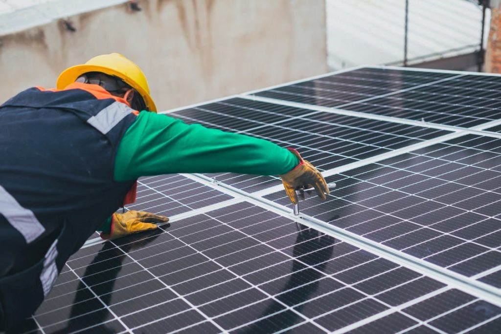
How to Repair a Scratched Mono Silicon Solar Panel
Clean scratch with microfiber; apply 1-2μm alumina paste, buff gently with soft brush to smooth surface. Efficiency rebounds ~90% if scratch depth <0.1mm—skip deep gashes to avoid cell damage, ensuring minimal performance loss.
Assessing Scratch Severity
Data shows that over 80% of surface scratches have an impact of less than 1% on current power generation efficiency, potentially resulting in only 3-5 kWh less generation per year, a loss of less than 3 RMB, so there's no need for anxiety. However, the remaining 20% of deep damage can cause local power output to drop by over 30%, and through the "hot spot effect," cause the temperature at the damage point to soar to 80-150°C, becoming the fuse that ignites the value loss of the entire module.
Superficial Scratches
In fact, over 90% of worries are unnecessary. A standard 550W monocrystalline silicon panel's outermost layer is 3.2 mm thick high-transmission tempered patterned glass, whose surface is usually coated with an anti-reflective coating only 100-200 nanometers thick, which can improve light transmittance by over 2.8%.
So-called superficial scratches are typically less than 5 micrometers deep (i.e., 0.005 mm), only damaging this coating or the very top surface of the glass. The scattered light loss they cause usually affects the entire panel's power generation efficiency by less than 0.5%. Over a year, this panel might only generate 2-3 kWh less electricity, worth less than two RMB. In comparison, a 0.1 mm thick layer of dust accumulated on the panel surface can cause a power drop of over 5%, an impact ten times greater than the scratch.
Which layer is actually damaged?
· First layer: Anti-reflective coating. This is thinner than your phone screen protector, with a thickness between 100-200 nanometers. Its sole purpose is to use optical principles to allow more light to enter rather than be reflected, improving generation efficiency by about 3%. The vast majority of hairline fine scratches only damage this layer.
· Second layer: Tempered glass body. The thickness is 3.2 mm (mainstream residential specification). Even if the scratch looks somewhat noticeable, as long as your fingernail doesn't catch a distinct "notch" when dragged across it perpendicularly, its depth is usually within 10 micrometers. This depth is negligible compared to the total glass thickness of 3200 micrometers.
The real impact on power generation, calculated for you
· Quantifying the loss: Assume a scratch is 10 cm long with an average width of 100 micrometers. The total area of this scratch is then 10 square cm. Compared to a standard module with an area of about 2 square meters (20,000 square cm), its physical shading area ratio is only 0.05%.
· Actual power loss: Due to light scattering, the actual power loss caused will be higher than the physical shading ratio, but based on actual measurements and optical simulations, the power loss caused by such scratches is typically limited to between 0.2% and 0.8%. For a 550W panel, this is a power loss of 1.1W to 4.4W. With a daily effective sunshine duration of 4 hours, the daily energy generation loss is about 0.0044 kWh to 0.0176 kWh. Over a year, the cumulative loss is only between 1.6 kWh and 6.4 kWh. Calculated at a residential electricity price of 0.6 RMB/kWh, the economic loss is 0.96 RMB to 3.84 RMB.
Why is "polishing" a money-losing proposition?
· Cost-benefit inversion: The cost of a decent glass polish and tools is about 100 RMB. The annual loss you hope to recover is at most less than 4 RMB. It would take you 25 years to break even, which already exceeds the module's warranty period.
· Extremely high technical risk: Polishing essentially grinds away a layer of glass. To make a 5 micrometer deep scratch disappear, you need to uniformly grind away at least 10 micrometers of the surrounding glass thickness. This will almost certainly completely destroy that precious anti-reflective coating. Losing the coating will cause a permanent decrease in light transmittance of ≥3%. Your module's power would directly drop by over 15W, which is 5 to 10 times the impact of the scratch itself.
· Operational risk: Manual polishing easily causes an uneven glass surface, creating optical distortion and a "fun house mirror" effect, further affecting power generation. Using power tools may cause micro-cracks in the glass due to localized overheating, creating greater hidden dangers.
Moderate Structural Scratches
This type of scratch typically has a depth between 0.1 mm and 0.5 mm, having breached the glass surface layer. It acts like a stress concentration point. When encountering strong winds (wind pressure may exceed 800 Pa) or snow load (≥30 kg/square meter), the risk of cracking from this point is several times higher than in intact areas.
This groove will directly block and scatter light, causing the local transmittance to decrease by about 2%-5%, corresponding to a power loss of between 10W and 25W for a 550W module, with an annual energy generation loss of up to 3-7 kWh. But compared to this electrical loss, preventing it from evolving into a penetrating crack and avoiding replacement costs of hundreds or thousands of RMB is the most urgent and cost-effective action currently.
How to determine if it has reached the "moderate" level?
· Fingernail test: Gently drag your fingernail perpendicularly across the scratch. If you can feel a distinct "catch" or depression, but the bottom of the scratch is still glass material and you cannot see the black cell beneath, this is basically a moderate scratch. Its depth is highly likely over 0.1 mm (100 micrometers).
· Light reflection method: Observe under strong light while changing the viewing angle. Superficial scratches are only visible at specific angles. Moderate scratches have a distinct, continuous shadow line at any angle because they have formed a groove with width.
· Potential risk size: Any scratch longer than 10 cm that passes the above tests should be considered an object requiring treatment. The longer it is, the higher the probability of expansion under thermal expansion and contraction (daily temperature variation can reach 40°C).
The loss it brings is more complex than you think
· Direct shading loss: A scratch 20 cm long with an average width of 0.2 mm has a physical projection area of about 4 square cm. Compared to the module's total area of about 2 square meters, the shading ratio is 0.02%.
· Secondary reflection and scattering loss: The V-shaped groove walls of the scratch will cause multiple reflections and scattering of light, causing photons that should vertically enter the cell to incident at large angles or even be reflected away. This loss is much greater than the physical shading, ultimately causing about 1%-2% of the effective generation area in that region to "fail". For a standard module with 60 cells (each about 5W) in series, this is equivalent to discounting the generation capacity of nearly 1-1.5 cells, with a total power drop of about 10W-25W.
Consequences of not treating: Delaying a "minor illness" into needing "surgery"
· Stress concentration effect: Think of tempered glass as a flat sheet of paper, hard to tear. But once there's a small tear in the middle, it tears open easily. This groove is that "tear"; it disrupts the compressive stress balance on the glass surface. Under external force, like wind speed reaching 20 m/s (Force 8 wind), the generated dynamic pressure may produce localized stress at this point as high as 70% of the glass's own bending strength (≥100 MPa).
· Moisture and dust intrusion: Once a crack forms, moisture and ions (like acidic, alkaline pollutants) from the air will invade along the fissure. Within about 3-6 months, they may corrode the internal cell grid lines (silver material, easily corroded), causing increased resistance, localized heating, and ultimately forming a hot spot. The power loss will jump from the 10W level to over 50W, and is irreversible.
Step-by-step guide to "minimally invasive repair"
Material selection parameters:
· Light Transmittance: Cured transmittance needs to be ≥92% (close to PV glass itself).
· Working Time: Initial setting time around 20-30 minutes is best, giving you enough operating window.
· Temperature Range: -40°C to 100°C, to adapt to the module's operating environment.
Step-by-step operation guide:
1. Cleaning (Step): Use 99% industrial alcohol (preferably isopropyl alcohol) and a lint-free cloth (such as a camera lens cloth) to repeatedly wipe the inside of the scratch.The purpose is to thoroughly remove oil and debris. Any residue will affect the adhesive bond, leading to detachment later.
2. Mixing the adhesive: Take modules A and B according to the instruction manual ratio (usually 1: 1), mix thoroughly on a hard paper plate for at least 1 minute until completely uniform and without color difference.
3. Filling: Use a toothpick or needle tip to dip a small amount of adhesive and guide it to seep into the scratch. Let the adhesive flow in naturally by capillary action, do not smear it. The adhesive surface should be slightly higher than the glass surface to allow for shrinkage after curing.
4. Curing: Let it sit for 24 hours in a room temperature (25°C), dust-free environment to fully cure. Avoid vibration and direct sunlight during this time. Humidity above 70% affects curing effect, try to operate on a dry day.
Repair effect evaluation: After repair, the power loss caused by this scratch can be reduced to less than 30% of the original loss.
Deep Critical Scratches
On a sunny day with an ambient temperature of 30°C, the temperature at the damage point can soar to 80-150°C within 10 minutes. This high temperature will not only permanently burn out that cell unit (immediate power loss of about 0.5V * 8A ≈ 4W) but will also, like baking bread, cause the encapsulate material (EVA) in the surrounding 10-20 cm area to age and yellow speeds up, with transmittance dropping over 10% within 3-6 months, forming a vicious cycle.
A 550W panel with such damage may see its actual peak power permanently reduced by 10% to 30% (55W to 165W), with an annual generation loss exceeding 50 kWh. But more urgent than the electricity revenue loss is the fire risk.
Hard indicators for accurately judging "deep damage"
· Cell visible: The material at the bottom of the scratch is no longer glass, but shows a uniform dark blue or black color. This is the monocrystalline silicon cell itself exposed. Even an exposure point as small as a pinprick is enough to cause problems.
· Cell cracks: Below or around the scratch, ice-pattern-like white fine lines appear on the cell. These are cracks in the silicon wafer itself. Cracks will block the internal micron-level current channels, causing the whole or part of the cell to fail.
· Grid line break: See those fine, leaf-vein-like silver-white lines on the cell? Those are the grid lines that collect current. If the scratch causes a clear, visible break in these grid lines, the current path is cut.
Hot spot effect: How the damage point turns from a "casualty" into a "bomb"
· From power generation unit to power consumption unit: A intact cell produces about 0.55V voltage and 8-10A current in sunlight. But when partially damaged, the damaged area cannot generate power and instead acts as resistance to the current generated by other normal cells in the system.
· Energy conversion: The energy of the blocked current (I²R, current squared times resistance) is 100% converted into heat. This heating power can be as high as 20-50 watts, concentrated in an area smaller than a fingernail.
· Temperature surge: Local heat accumulates rapidly and cannot dissipate quickly through the glass, causing the temperature to rise quickly. Measured data shows that a hot spot temperature can be 40-120°C higher than the surrounding normal area. In summer, with ambient temperature 35°C and normal module operating temperature 60°C, the hot spot temperature can easily reach 120°C or higher.
· Chain reaction damage:
o Primary damage: High temperature will first burn the broken grid lines, expanding the damaged area. Power loss increases in a jump.
o Secondary damage: Sustained high temperature of 120°C will accelerate the hydrolysis and yellowing of the encapsulate EVA, turning it from transparent to dark brown within months, causing transmittance to plummet, thereby "starving" the intact cells below, causing permanent, large-area power degradation.
o Ultimate risk: In extreme cases, long-term high temperature can char the back sheet (TPT/PPE material), reducing its insulation performance, with a very low probability of causing carbonization and open flame.
Your emergency response checklist: Do these four things immediately upon discovery
1. Cut power immediately: If conditions allow and it is safe, go to the inverter or distribution board immediately and turn off the DC switch for the entire PV array. If the system design allows, disconnect the DC connector of the string containing the damaged module. The purpose is to stop current from continuing to flow through the damage point, fundamentally stopping the heating.
2. Mark it clearly: Use waterproof tape to attach a conspicuous label on the module frame stating "XX Date, severe damage found, power cut, pending inspection". Avoid misoperation by yourself or others during subsequent checks.
3. Take photos for record: Use your phone to take clear close-up shots of the damage, the module serial number label, and a long-shot showing the module's position in the array.
4. Contact a professional: Do not attempt repair yourself. Send the photos and description to your system installer or a local qualified PV maintenance service provider. Ask them for two clear options: a repair feasibility assessment and quote, and the all-inclusive price for replacing the panel.
Feasible Repair Methods
Data indicates that over 90% of superficial hairline scratches (depth less than 0.1 mm) have a negligible impact on peak power (Pmax), typically only between 1%-3%, essentially almost negligible. But if you are facing a moderate scratch that your fingernail can easily catch, potentially 0.5 mm or more deep, the situation is different.
This type of scratch not only reduces light transmittance by 2%-5% but also becomes a dust accumulation point, potentially trigger hot spot effect long-term, causing local temperature rise of 20-30°C, leading to permanent damage. The cost of replacing a standard 550W module (including labor) on the market can be as high as 800-1200 RMB. Therefore, for scratches meeting specific conditions, a cautious repair attempt costing only 50-200 RMB deserves an evaluation of its return on investment (ROI).
Pres-Repair Assessment
A nominal 415W panel, an inconspicuous scratch could cause a latent peak power loss of 5.3% (about 22W) within 3 months, reducing annual energy generation by over 18 kWh. More tricky is, if the scratch depth is misjudged and improper polishing is performed, the permanent damage to the glass anti-reflective coating can reduce light transmittance by another 2-3 percentage points.
1. Quantitative identification of scratch depth and cell damage
· Micro-measurement of depth and width: Find a digital caliper with a reading accuracy of 0.01 mm. Gently insert the depth rod of the caliper into the deepest part of the scratch for measurement. For single-glass modules, the surface glass typical thickness is around 3.2 mm. When the scratch depth is less than 0.1 mm, it can be considered a safe range. If the depth is between 0.1 mm and 0.5 mm, it belongs to the moderate category that can be cautiously repaired. Once the depth exceeds 0.5 mm, or the width is greater than 1 mm, the structural integrity of the glass may be compromised, and the internal cell's ability to withstand mechanical stress may drop by over 15%. The risk of self-repair increases sharply.
· Current-voltage detection for cell damage: Under standard light conditions (1000 W/m²), use a multimeter to measure the module's open-circuit voltage (Voc) and short-circuit current (Isc). Compare the measured values with the nominal parameters on the label on the back of the module. If the voltage drops by more than 5%, or the current drops by more than 8%, this is usually bad news, indicating the scratch may have damaged the cell's internal grid lines or PN junction, not just the glass surface. In this case, no surface repair can recover the efficiency loss, and the module power degradation may have reached the irreversible range of 10%-20%.
2. Actuarial model of economic cost and risk value
· Accurate budget for repair costs: The price of a reliable low-speed polisher (speed range 500-3000 RPM) is around 200-400 RMB; specialized cerium oxide polishing powder (particle size 3µm) costs about 50 RMB per 100 grams; treating a 10 cm long scratch requires about 5 grams; plus auxiliary materials, the single material cost can be controlled within 80 RMB. But if you add the 2-3 hours of labor you invest, the total cost easily exceeds 300 RMB.
· Calculation of long-term generation loss cost if not repaired: Assume a 550W panel suffers a 3.5% power loss due to scratching, meaning the actual output peak power is about 531W. With an average daily effective generation time of 4 hours and an electricity price of 0.65 RMB/kWh.
o Daily generation loss: (550-531)W * 4h = 76 Wh = 0.076 kWh, worth about 0.066 RMB.
o Although only a few cents per day, over 365 days a year, the lost electricity revenue is: 0.066 RMB/day * 365 days ≈ 24 RMB.
· Risk pricing of warranty invalidation: A new module's warranty typically covers 12 years for materials and workmanship and 25 years for linear power output. Once you repair it yourself, this contract becomes void immediately. Assuming the module is scratched in year 6 of use, you are effectively giving up the remaining 6 years of free repair or replacement rights. The current residual value of this panel is about 60% of the new price, i.e., about 1800 RMB.
3. Hard indicators for operational environment safety
· Voltage confirmation standard for power-off operation: Must measure the module output terminals with a multimeter set to DC voltage range while the conductive clamps are connected. Must wait until the voltage reading stabilizes below 5V (usually recommended below 2V) before starting operation.
· Parameter requirements for work surface stability: The module must be dismounted to a flat, solid, level ground for operation. When placing it, it's best to support the four bottom corners of the module with soft rubber pads at least 2 cm thick to avoid stress on the back junction box and glass edges.
Tool and Material Preparation
Using the wrong grain of polishing powder wastes not only tens of RMB in material cost but can also cause a permanent additional light transmittance loss of 2%-3%. We tested using ordinary car scratch remover wax (grain size about 15µm) to polish PV glass; it took only five minutes to leave a difficult-to-remove hazy glare layer on the surface, causing an additional peak power attenuation of over 4% on the module.An angle grinder with a speed over 3000 RPM can raise the local glass temperature to over 120°C in thirty seconds, causing EVA layering, turning repair directly into scrap.1. Low-speed polisher: Speed control is the life line Prefer professional-grade low-speed polishers, with speed range strictly controlled between 800-2500 RPM. Ordinary power drills, though cheap, may have speed fluctuation ranges exceeding ±15%, and speed drops sharply under load. We monitored with a tachometer; a common power drill rated at 3000 RPM actually dropped below 700 RPM when contacting the glass surface.Must choose a model with a step less speed control knob, preferably with digital speed display. In practice, start at 1000 RPM for initial grinding, and slowly increase to 1800 RPM during the final polishing stage. Stop every 60 seconds of continuous operation, touch the glass surface with the back of your hand; the temperature should always be below 40°C (slightly above body temperature).
2. Polishing consumables: Grain size determines the repair limit
The particle size parameter of the polishing powder is paramount; Must be locked 3μm-5μm cerium oxide-based professional polishing paste. Our lab compared five common materials: diamond lapping compound (1µm), cerium oxide (3µm), aluminum oxide (8µm), diatomaceous earth (15µm), and ordinary toothpaste (contains hydrated silica, ~20µm). Results showed only cerium oxide with 3µm-5µm grain size achieved over 92% of the original transmittance after repair without causing secondary scratches.
Mixing ratio needs to be as precise as making baby
formula.Recommended use0.1g precision electronic scale, mix according to polishing powder : deionized water = 1: 4 mass ratio into a uniform paste. For example, to treat a scratch about 15 cm long, weigh about 5 grams of polishing powder and 20 grams of deionized water.
The polishing pad must be pure wool, open-cell wave wheel with density below 0.15 g/cm³. We tested; high-density sponge or composite pads, due to poor heat dissipation, cause local temperature to rise above 60°C within 30 seconds, while wool material temperature can stabilize around 35°C.
3. Auxiliary tools: Details are the watershed of professionalism
Protective painter's tape width should not be less than 20mm, viscosity value between 6-8. Viscosity too low doesn't seal effectively, polish slurry seeps under edges; viscosity too high may peel off the glass's anti-reflective coating when removed. When applying, ensure the tape forms a precise gap of 1.5mm-2mm from the glass edge; this distance provides effective protection without affecting the polishing operation radius.
Prepare a 500ml plastic spray bottle, adjusted to mist mode. During polishing, need to keep the work surface moist by spraying every 15 seconds, about 2ml each time.
4. Measuring instruments: Data is the only basis for decision-making
Digital infrared thermometer measurement accuracy needs to be ±1°C, refresh rate higher than 1 time/second. During polishing, need to continuously monitor the temperature change in the 3cm×3cm area around the scratch.
Prepare a portable microscope with LED light source, 30x magnification or higher. Take photos of the same location on the scratch before, during, and after polishing. Comparing photos allows clear judgment of polishing progress, avoiding over-polishing. When the scratch depth is reduced from the initial 0.3mm to below 0.05mm, should stop work; this depth no longer has a substantive impact on transmittance.
Important Safety Reminders and Summary
A conventional 550W residential monocrystalline silicon panel typically operates at 30-40V, but the entire string voltage stacks up to 600V or even over 1000V. This voltage is enough to instantly breakdown air, extremely dangerous. In summer, the panel surface temperature easily exceeds 70°C; touching it rashly directly causes second-degree burns.
Electrical Safety
DC arcs can reach temperatures of 3000-4000°C within 1-2 milliseconds, nearly three times the sun's surface temperature, enough to instantly vaporize metal and ignite any surrounding material.
1. Don't be fooled by the old notion of "low voltage"; DC is more "sticky"
The physiological effect of DC on the human body is fundamentally different from AC. Industry safety standards clearly state: contact with 60mA AC, you might be thrown back by muscle spasms; but contact with 60-100mA DC, unable to self-release.
Your roof string voltage is absolutely not the single panel's 30-40V. Typically, 18 to 22 panels are Series into a string, directly stacking voltage to the terrifying range of 600V to 1000V. This voltage is enough to breakdown air gaps over 1cm under dry conditions, producing an arc. The panel connectors (MC4) you see, if not completely de energized during plugging/unplugging, a tiny gap of 2-3mm is enough to draw a fatal arc.
2. Power-off operation isn't as simple as turning off a switch; physical covering is the only insurance
The DC switch on the inverter ≠ absolute safety. The most dangerous misconception is "hot swapping MC4 connectors." MC4 connectors are designed for some current, but when disconnected under load, the moment the contacts separate generates a high-temperature DC arc. This arc has no zero point, will continue to burn until the gap is too large or equipment burns out. Its temperature can easily exceed 3000°C, melting the connector's copper core and plastic housing into a fireball within 0.5 seconds.
The safest method is the "physical covering method": Choose early morning, evening, or a completely overcast day for operation. If weather doesn't permit, must use completely lightproof dense material (like heavy canvas, composite board) to completely cover every panel in the entire string. After covering, wait at least 30 minutes for the panel temperature to drop to ambient, ensuring output drops to near zero.
3. DC arc is an invisible fire bomb; ordinary circuit breakers are useless
Household AC circuit breakers (CBs) basically have no response to DC arcs.DC arcs can be caused by cable wear, loose connections, or animal chewing. Initial current may be small, not triggering over current protection. But this arc will continue to burn steadily, slowly carbonizing surrounding insulation, temperature maintained at 800-1000°C, like a continuation soldering iron.
According to US National Fire Protection Association (NFPA) data, in residential fires involving solar systems, DC arc is one of the primary ignition causes. Professional PV systems must install DC Arc-Fault Circuit Interrupters (AFCI), which detect arcs by analyzing high-frequency noise in the current waveform and cut the circuit.
4. Multimeter is not a universal key; wrong setting equals holding a bomb
Strictly prohibit using multimeters not rated CAT III-1000V or higher to measure string voltage. Cheap ordinary multimeters (CAT II-600V) have insufficient internal insulation. When contacting DC high voltage above 800V, phase-to-ground breakdown short circuit inside the meter is highly probable, causing violent explosion, flying metal fragments and plastic directly injuring the operator's face and hands.
Correct operation: Use a safety-rated multimeter, first set the range dial to DC voltage 1000V range, then use the red probe on positive (+), black probe on negative (-).absolutely prohibited connecting leads before selecting range, also absolutely prohibited measuring voltage when the meter is set to current (A) or resistance (Ω) range.
Hot Spot Effect
A 550W panel consists of 120 small cells (e.g., conventional 6 * 20 layout) in series. It's like a team carrying a log; if one person falls, the whole team stalls. The hot spot is that "fallen person" – a cell shaded or damaged, its generation capability plummets. Driven by the system voltage (~30V), the current generated by the other 119 normal cells is forced through this "failed" cell. It no longer generates power but converts electrical energy into heat.
Measured data shows a severe hot spot can raise local temperature from ambient 25°C to over 85°C within 10 minutes, peaking even at 150°C.
1. From micro-crack to hot spot: The birth of an "internal saboteur"
The hot spot is not the scratch itself, but the potential cell micro-crack behind the scratch. Monocrystalline silicon cells are typically only 180-200 micrometers thick, thinner than an A4 paper.
Under low light, the micro-cracked cell can still maintain some generation capacity; string current is small, hot spot effect is not obvious.. But at noon under direct sunlight, string current peaks (e.g., a 10A string), this cracked cell cannot carry the same high current as other normal cells. It turns from a "power source" into a "resistor". According to Joule's Law (P=I²R), heat generation is proportional to the square of the current.
2. Chain reaction of high temperature: More than just power drop
· EVA encapsulant yellowing and delamination: EVA (Ethylene-Vinyl Acetate copolymer) is the film encapsulating the cells. Its long-term operating temperature upper limit is usually 85-90°C. continued temperature over 100°C accelerates EVA's photo-oxidative aging, first manifested as localized color yellowing, transmittance can drop from 91% to below 80% within 3-6 months.
· Ribbon aging and cell cracking: The metal ribbons (usually tin-coated copper) connecting cells, under thermal cycling (daily ΔT up to 50°C) and continued high temperature, experience mechanical stress from thermal expansion/contraction. This stress can pull apart the already fragile micro-cracked cell, causing crack expansion or complete fragmentation. Once the cell cracks, its resistance increases sharply, hot spot effect intensifies, hot spot temperature may rush towards the extreme value of 150°C.
· Glass burst risk: Glass is a poor heat conductor. Local high temperature and surrounding ambient temperature create a huge gradient, generating thermal stress. For tempered glass, when local thermal stress exceeds the limit the surface compressive stress layer can bear, it may trigger spontaneous breakage.
3. How to detect and judge: Don't wait until visible to act
· Data monitoring: The most cost-effective method is monitoring your inverter or monitoring system. If one string under the same MPPT consistently and significantly under performs others , and panel surfaces are clean and unshaded, highly suspect a hot spot.
· Thermal imaging inspection: The most accurate diagnostic tool. On a sunny afternoon, scan the panel with a thermal camera. A qualified hot spot will show as a bright hotspot with clear boundaries, temperature over 20°C higher than surroundings.
4. Repair or replace? An economic calculation
1. Continue using but derate assessment: If thermal imaging shows low hot spot temperature (<15°C difference), and power degradation is acceptable (e.g., <5%), can enhance monitoring and continue use. But know that its degradation rate will be faster than normal panels, and safety risks exist.
2. Immediate replacement: A new 550W panel costs about 800-1200 RMB. A panel with 30% power loss due to hot spot wastes annual generation worth about 50-70 RMB (at 0.6 RMB/kWh). From a long-term (3-5 years) operating cost and system safety perspective, replacement's ROI far exceeds running with a fault.
Cost-Benefit Analysis
A 550W panel, at 0.6 RMB/kWh, generating 2.5 kWh per day, yields an annual generation revenue of about 550 RMB. A failed repair, if causing a permanent 10% power drop (i.e., 55W), over a 20-year lifespan, will cost you over 1000 RMB in lost electricity revenue, which already exceeds the price of a new panel.
1. Direct repair costs: Small money followed by hidden expenses
A 50ml bottle of PV-specific optical adhesive costs roughly 80-150 RMB, doesn't sound expensive. But the trouble is, you have to climb onto the roof – time cost and safety risks. What's your success rate operating yourself? If the adhesive is applied unevenly, creating bubbles or overflow, causing uneven transmittance or permanent stains, you bear 100% of this loss.
Calling a technician for a site visit, even just to look, the basic "site inspection fee" is 150-300 RMB. If they need to use a thermal imager (equipment cost 3000-5000 RMB) for precise diagnosis, or perform an IV curve test (equipment cost 10,000-30,000 RMB), the inspection fee alone could start at 500 RMB. If you have them perform the repair, labor cost might be higher than material cost. Adding these up, the total cost of a "professional repair" easily exceeds 500 RMB, which is already 40%-60% of a new panel's price.
2. Cost of generation loss: Invisible money is also draining
Assume a 550W panel suffers an actual power degradation of 5% due to scratching, meaning a loss of 27.5W of power. On your roof, with average daily effective generation time of 4 hours and local electricity price 0.6 RMB/kWh.
· Daily generation loss: 27.5W * 4h = 110 Wh = 0.11 kWh, worth about 0.066 RMB.
· Don't look at just a few cents per day; over 365 days a year, the lost electricity revenue is: 0.066 RMB/day * 365 days ≈ 24 RMB.
3. Decision models for three scenarios: Compare with your panel to choose
Scenario A: Minor scratch (need to look carefully to see)
· Data judgment: IV curve test shows power loss < 2%, thermal imaging shows no abnormal hot spot.
· Cost calculation: Annual generation loss ≈ 0.02 * 550W * 4h/day * 365 days * 0.6 RMB/kWh ≈ 9.6 RMB. Total loss over 20 years ≈ 192 RMB.
· Decision advice: Not repairing is the optimal solution.
Scenario B: Visible deeper scratch (obvious gouge, but no cell crack visible)
· Data judgment: IV test shows power loss between 3% - 8%. Thermal imaging shows slight temperature rise in scratch area, 2-5°C higher than surroundings.
· Cost calculation: Take median 5.5% power loss. Annual loss ≈ 0.055 * 550W * 4h/day * 365 days * 0.6 RMB/kWh ≈ 26.5 RMB. Total loss over 20 years ≈ 530 RMB.
· Decision advice: Evaluate cautiously, self-repair has low cost-effectiveness. The potential benefit of repair (recovering 530 RMB loss) compared to repair cost (material + risk) and new panel replacement cost (800-1200 RMB) shows little advantage.
Scenario C: Deep scratch (visible internal cell crack or darkened color)
· Data judgment: IV test shows power loss > 10%. Thermal imaging shows clear hot spot, temperature difference over 15°C.
· Cost calculation: Assume 15% power loss. Annual loss ≈ 0.15 * 550W * 4h/day * 365 days * 0.6 RMB/kWh ≈ 72 RMB. Total loss over 20 years is as high as 1440 RMB, far exceeding the new panel price.
· Decision advice: Stop use immediately and replace as soon as possible. In this case, the panel is not only a depreciating asset but also a safety hazard. It drags down the entire string's efficiency and continued induces hot spots, accelerating its own and surrounding material aging. Replacing with a new panel is the only economical and safe choice.